instrument cluster FORD E SERIES 1999 4.G Owners Manual
[x] Cancel search | Manufacturer: FORD, Model Year: 1999, Model line: E SERIES, Model: FORD E SERIES 1999 4.GPages: 208, PDF Size: 1.93 MB
Page 6 of 208
0 1020304050
60
70
80
90
10 020 km/h406080
10 0
12 0
14 0H
L
16 0MPH
000000
0000
BRAKE
18
8
SERVICE
ENGINE SOON
FH
C
E
ON
OFFRES
SET
ACCEL
COAST
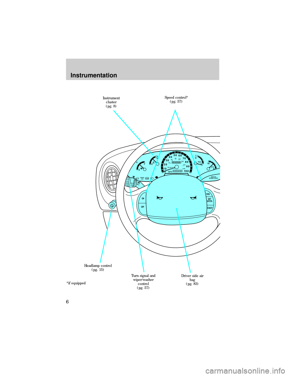
Instrument
cluster
(pg. 8)
Driver side air
bag
(pg. 83) Speed control*
(pg. 57)
Turn signal and
wiper/washer
control
(pg. 57) Headlamp control
(pg. 15)
*if equipped
Instrumentation
6
Page 86 of 208
Several air bag system components get hot after inflation. Do not
touch them after inflation.
If the air bag is deployed,the air bag will not function again
and must be replaced immediately.If the air bag is not
replaced, the unrepaired area will increase the risk of injury in a
collision.
The SRS consists of:
²driver and passenger air bag modules (which include the inflators and
air bags),
²one or more impact and safing sensors,
²a readiness light and tone
²and the electrical wiring which connects the components.
The diagnostic module monitors its own internal circuits and the
supplemental air bag electrical system warning (including the impact
sensors), the system wiring, the air bag system readiness light, the air
bag back up power and the air bag ignitors.
Determining if the system is operational
The SRS uses a readiness light in the instrument cluster or a tone to
indicate the condition of the system. Refer to theAir bag readiness
section in theInstrumentationchapter. Routine maintenance of the air
bag is not required.
A difficulty with the system is indicated by one or more of the following:
²The readiness light will either
flash or stay lit.
²The readiness light will not
illuminate immediately after
ignition is turned on.
²A series of five beeps will be heard. The tone pattern will repeat
periodically until the problem and light are repaired.
If any of these things happen, even intermittently, have the SRS serviced
at your dealership or by a qualified technician immediately. Unless
serviced, the system may not function properly in the event of a
collision.
Seating and safety restraints
86
Page 104 of 208

ABS warning lamp
TheABSwarning lamp in the instrument cluster momentarily illuminates
when the ignition is turned on and the engine is off. If the light does not
illuminate momentarily at start up, remains on or continues to flash, the
ABS needs to be serviced.
With the ABS light on, the anti-lock
brake system is disabled and normal
braking is still effective unless the
brake warning light also remains
illuminated with parking brake
released. (If your brake warning lamp illuminates, have your vehicle
serviced immediately).
Using ABS
²In an emergency or when maximum efficiency from the ABS is
required, apply continuous full force on the brake. The ABS will be
activated immediately, thus allowing you to retain full steering control
of your vehicle and, providing there is sufficient space, will enable you
to avoid obstacles and bring the vehicle to a controlled stop.
²The Anti-Lock system does not decrease the time necessary to apply
the brakes or always reduce stopping distance. Always leave enough
room between your vehicle and the vehicle in front of you to stop.
²We recommend that you familiarize yourself with this braking
technique. However, avoid taking any unnecessary risks.
Rear anti-lock brake system (RABS) (if equipped)
Rear Anti-lock Brake System (RABS) is designed to help you maintain
directional stability in emergency stopping situations. With RABS, the
rear brakes are kept from locking during panic stops; however, the front
wheels can lock because they are not controlled by RABS.
A clicking noise and slight pedal pulsation during RABS braking events
indicates the RABS is functioning. Pedal pulsation coupled with clicking
noise while braking under panic conditions on loose gravel, wet or snowy
roads is normal and indicates proper functioning of the vehicle's RABS. If
the vehicle has continuous vibration or shudder in the steering wheel
while braking, the vehicle should be inspected by a qualified service
technician.
The RABS operates by detecting the onset of rear wheel lockup during
brake applications and compensating for this tendency.
!
BRAKE
Driving
104
Page 105 of 208
RABS warning lamp
TheABSwarning lamp in the instrument cluster illuminates if a RABS
fault is detected. Have your vehicle serviced as soon as possible.
Normal braking is still effective
unless the BRAKE warning lamp is
also illuminated.
Using RABS
²In an emergency, applying full pressure may cause the front wheels to
lock.If the front brakes lock, the vehicle cannot be steered.Yo u
should apply the brakes with steadily increasing force, as if
ªsqueezingº the brakes. If you feel the front wheels begin to lock,
momentarily release the pedal and repeat the ªsqueezeº technique.
²We recommend that you familiarize yourself with how the RABS
performs. However, avoid unnecessary risks.
Parking brake
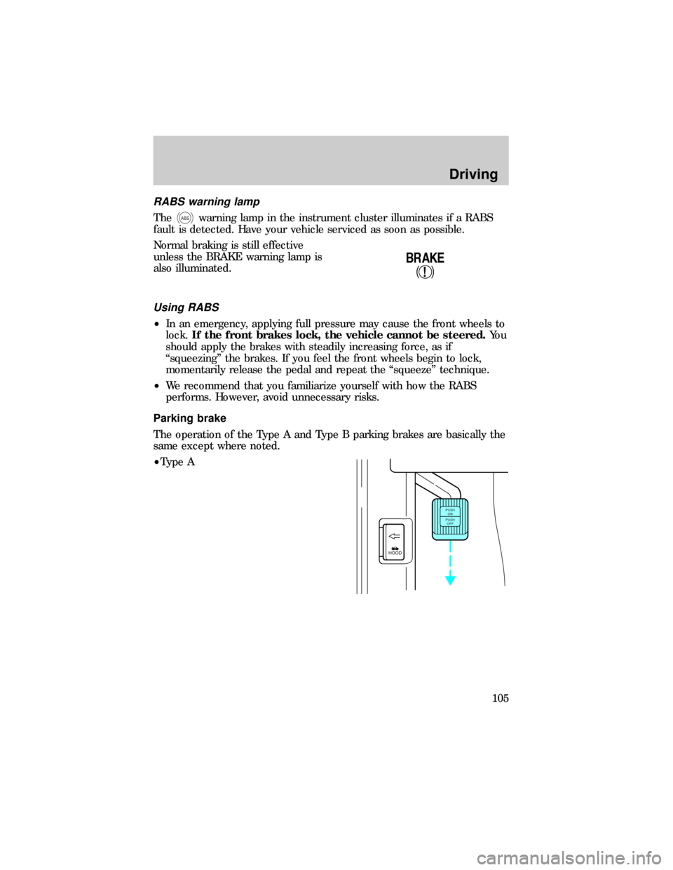
The operation of the Type A and Type B parking brakes are basically the
same except where noted.
²Type A
!
BRAKE
HOOD
PUSH
ON
PUSH
OFF
Driving
105
Page 106 of 208
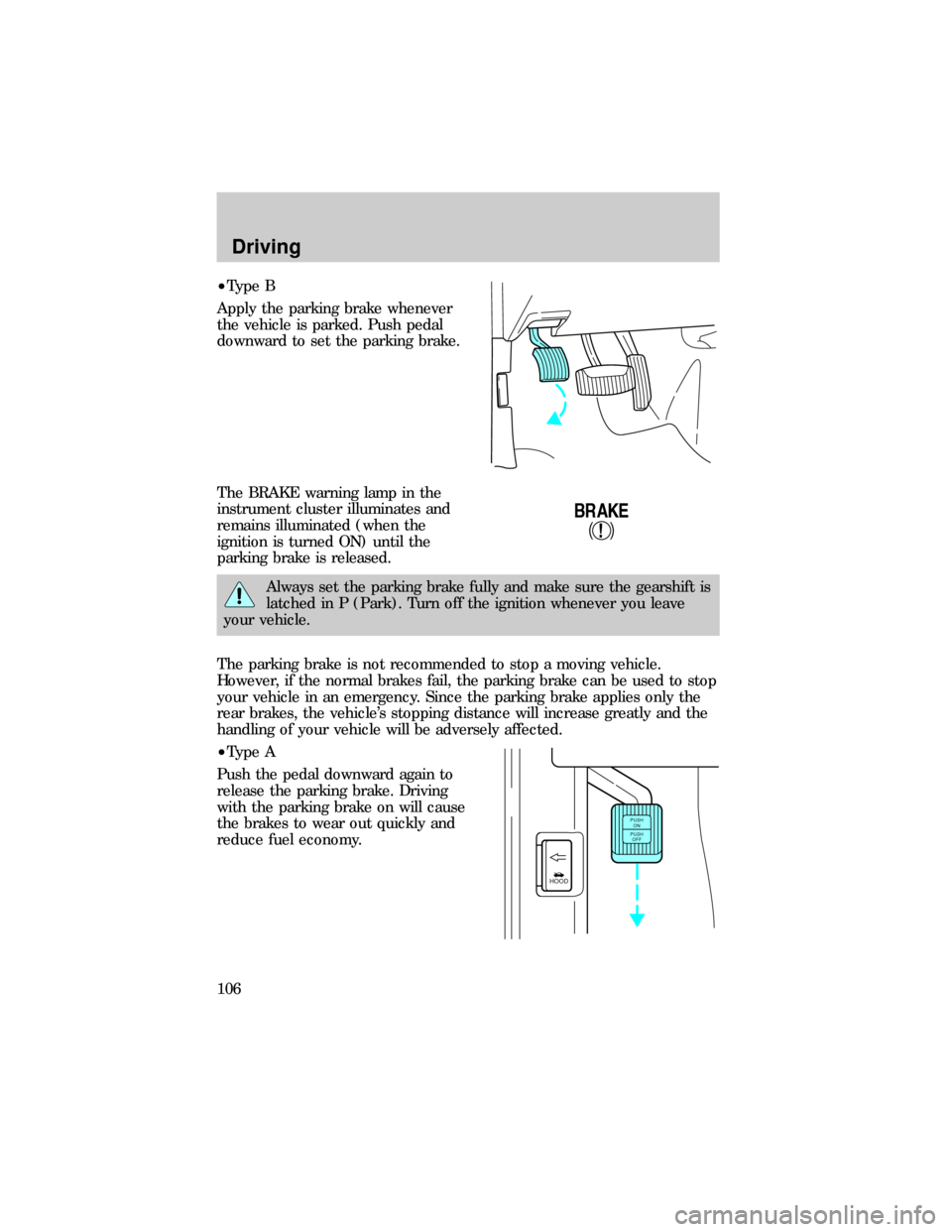
²Type B
Apply the parking brake whenever
the vehicle is parked. Push pedal
downward to set the parking brake.
The BRAKE warning lamp in the
instrument cluster illuminates and
remains illuminated (when the
ignition is turned ON) until the
parking brake is released.
Always set the parking brake fully and make sure the gearshift is
latched in P (Park). Turn off the ignition whenever you leave
your vehicle.
The parking brake is not recommended to stop a moving vehicle.
However, if the normal brakes fail, the parking brake can be used to stop
your vehicle in an emergency. Since the parking brake applies only the
rear brakes, the vehicle's stopping distance will increase greatly and the
handling of your vehicle will be adversely affected.
²Type A
Push the pedal downward again to
release the parking brake. Driving
with the parking brake on will cause
the brakes to wear out quickly and
reduce fuel economy.
!
BRAKE
HOOD
PUSH
ON
PUSH
OFF
Driving
106
Page 127 of 208
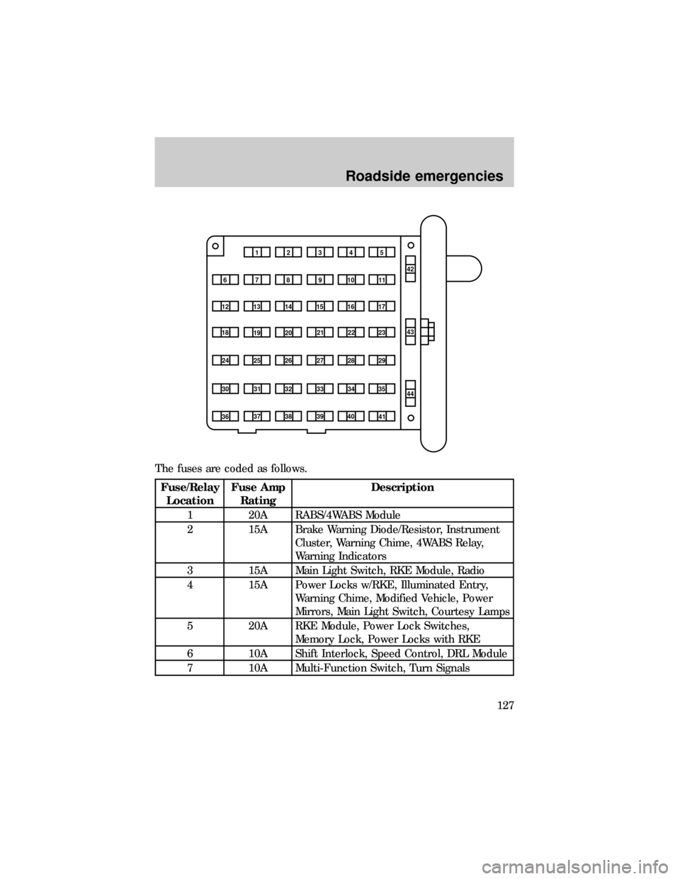
The fuses are coded as follows.
Fuse/Relay
LocationFuse Amp
RatingDescription
1 20A RABS/4WABS Module
2 15A Brake Warning Diode/Resistor, Instrument
Cluster, Warning Chime, 4WABS Relay,
Warning Indicators
3 15A Main Light Switch, RKE Module, Radio
4 15A Power Locks w/RKE, Illuminated Entry,
Warning Chime, Modified Vehicle, Power
Mirrors, Main Light Switch, Courtesy Lamps
5 20A RKE Module, Power Lock Switches,
Memory Lock, Power Locks with RKE
6 10A Shift Interlock, Speed Control, DRL Module
7 10A Multi-Function Switch, Turn Signals
1234
5
7
689101142
43
44 13 12 14
15 16 17
19 18
2021 22 23
25 24
26 27 28 29
31 30 32 33 3435
37
3638 3940
41
Roadside emergencies
127
Page 128 of 208
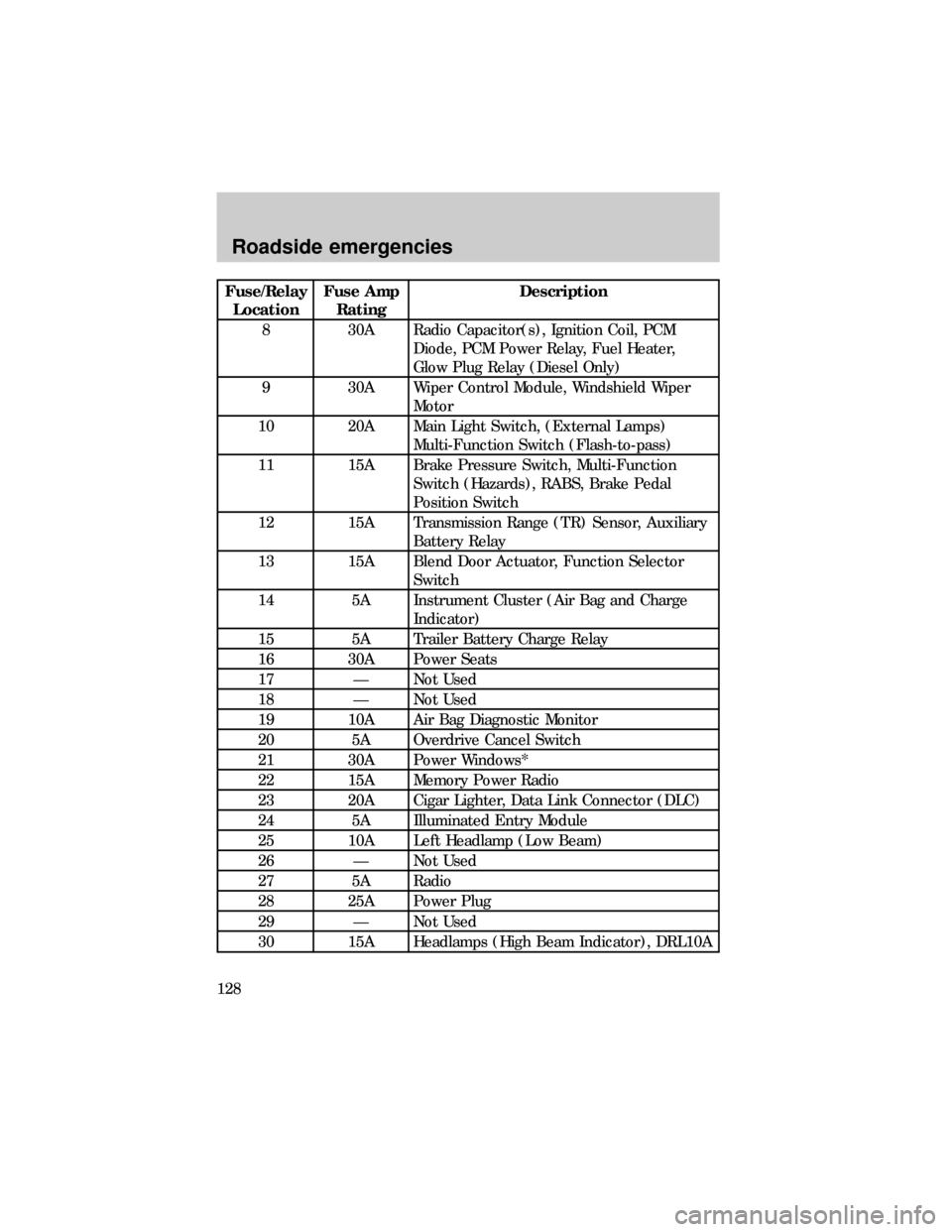
Fuse/Relay
LocationFuse Amp
RatingDescription
8 30A Radio Capacitor(s), Ignition Coil, PCM
Diode, PCM Power Relay, Fuel Heater,
Glow Plug Relay (Diesel Only)
9 30A Wiper Control Module, Windshield Wiper
Motor
10 20A Main Light Switch, (External Lamps)
Multi-Function Switch (Flash-to-pass)
11 15A Brake Pressure Switch, Multi-Function
Switch (Hazards), RABS, Brake Pedal
Position Switch
12 15A Transmission Range (TR) Sensor, Auxiliary
Battery Relay
13 15A Blend Door Actuator, Function Selector
Switch
14 5A Instrument Cluster (Air Bag and Charge
Indicator)
15 5A Trailer Battery Charge Relay
16 30A Power Seats
17 Ð Not Used
18 Ð Not Used
19 10A Air Bag Diagnostic Monitor
20 5A Overdrive Cancel Switch
21 30A Power Windows*
22 15A Memory Power Radio
23 20A Cigar Lighter, Data Link Connector (DLC)
24 5A Illuminated Entry Module
25 10A Left Headlamp (Low Beam)
26 Ð Not Used
27 5A Radio
28 25A Power Plug
29 Ð Not Used
30 15A Headlamps (High Beam Indicator), DRL10A
Roadside emergencies
128
Page 130 of 208
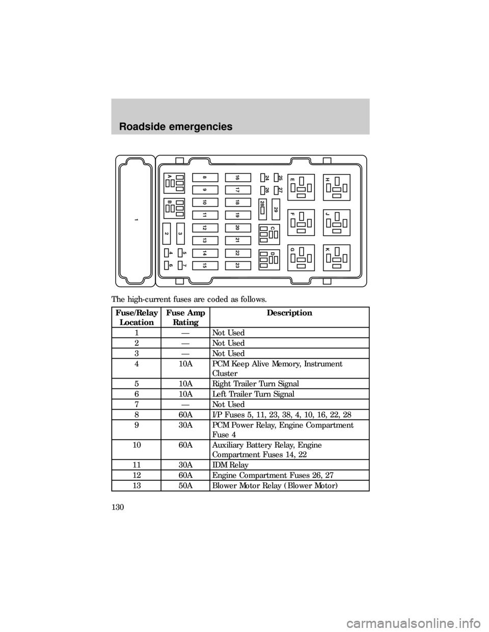
The high-current fuses are coded as follows.
Fuse/Relay
LocationFuse Amp
RatingDescription
1 Ð Not Used
2 Ð Not Used
3 Ð Not Used
4 10A PCM Keep Alive Memory, Instrument
Cluster
5 10A Right Trailer Turn Signal
6 10A Left Trailer Turn Signal
7 Ð Not Used
8 60A I/P Fuses 5, 11, 23, 38, 4, 10, 16, 22, 28
9 30A PCM Power Relay, Engine Compartment
Fuse 4
10 60A Auxiliary Battery Relay, Engine
Compartment Fuses 14, 22
11 30A IDM Relay
12 60A Engine Compartment Fuses 26, 27
13 50A Blower Motor Relay (Blower Motor)
AB3
2
146 5715 14 13 12 11 10 9 823 22 21 20 19 18 17 1624 26 25 27
29
CDG F EK J H
28
Roadside emergencies
130