steering wheel FORD E SERIES 2002 4.G Owners Manual
[x] Cancel search | Manufacturer: FORD, Model Year: 2002, Model line: E SERIES, Model: FORD E SERIES 2002 4.GPages: 272, PDF Size: 2.6 MB
Page 1 of 272
Introduction 4
Congratulations 4
Safety and environment protection 5
Symbol glossary 10
Instrument cluster 12
Warning and control lights 12
Gauges 16
Entertainment systems 20
AM/FM stereo 20
AM/FM stereo cassette 20
AM/FM stereo cassette with CD 31
AM/FM stereo with CD 41
Climate controls 78
Heater only 78
Manual heating and air conditioning 79
Lights 85
Headlamps 85
Bulb replacement 88
Driver controls 94
Windshield wiper/washer control 94
Steering wheel adjustment 95
Power windows 96
Mirrors 97
Locks and security 108
Keys 108
Locks 108
Anti-theft system 109
Table of contents
1
Page 95 of 272
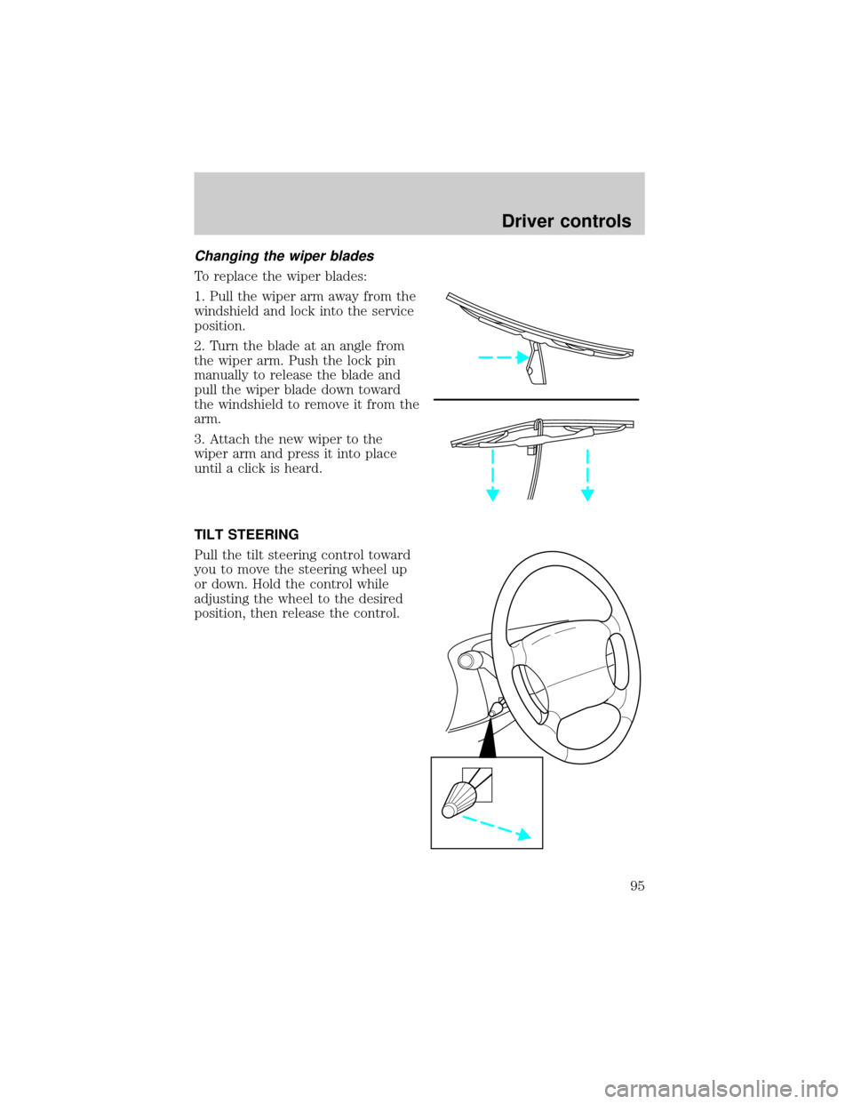
Changing the wiper blades
To replace the wiper blades:
1. Pull the wiper arm away from the
windshield and lock into the service
position.
2. Turn the blade at an angle from
the wiper arm. Push the lock pin
manually to release the blade and
pull the wiper blade down toward
the windshield to remove it from the
arm.
3. Attach the new wiper to the
wiper arm and press it into place
until a click is heard.
TILT STEERING
Pull the tilt steering control toward
you to move the steering wheel up
or down. Hold the control while
adjusting the wheel to the desired
position, then release the control.
Driver controls
95
Page 96 of 272
Never adjust the steering wheel when the vehicle is moving.
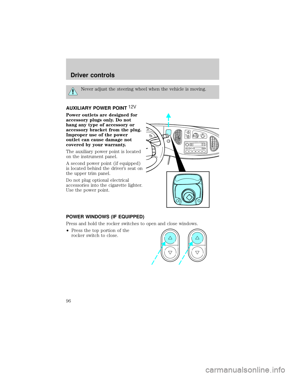
AUXILIARY POWER POINT
Power outlets are designed for
accessory plugs only. Do not
hang any type of accessory or
accessory bracket from the plug.
Improper use of the power
outlet can cause damage not
covered by your warranty.
The auxiliary power point is located
on the instrument panel.
A second power point (if equipped)
is located behind the driver's seat on
the upper trim panel.
Do not plug optional electrical
accessories into the cigarette lighter.
Use the power point.
POWER WINDOWS (IF EQUIPPED)
Press and hold the rocker switches to open and close windows.
²Press the top portion of the
rocker switch to close.
Driver controls
96
Page 148 of 272
STARTING
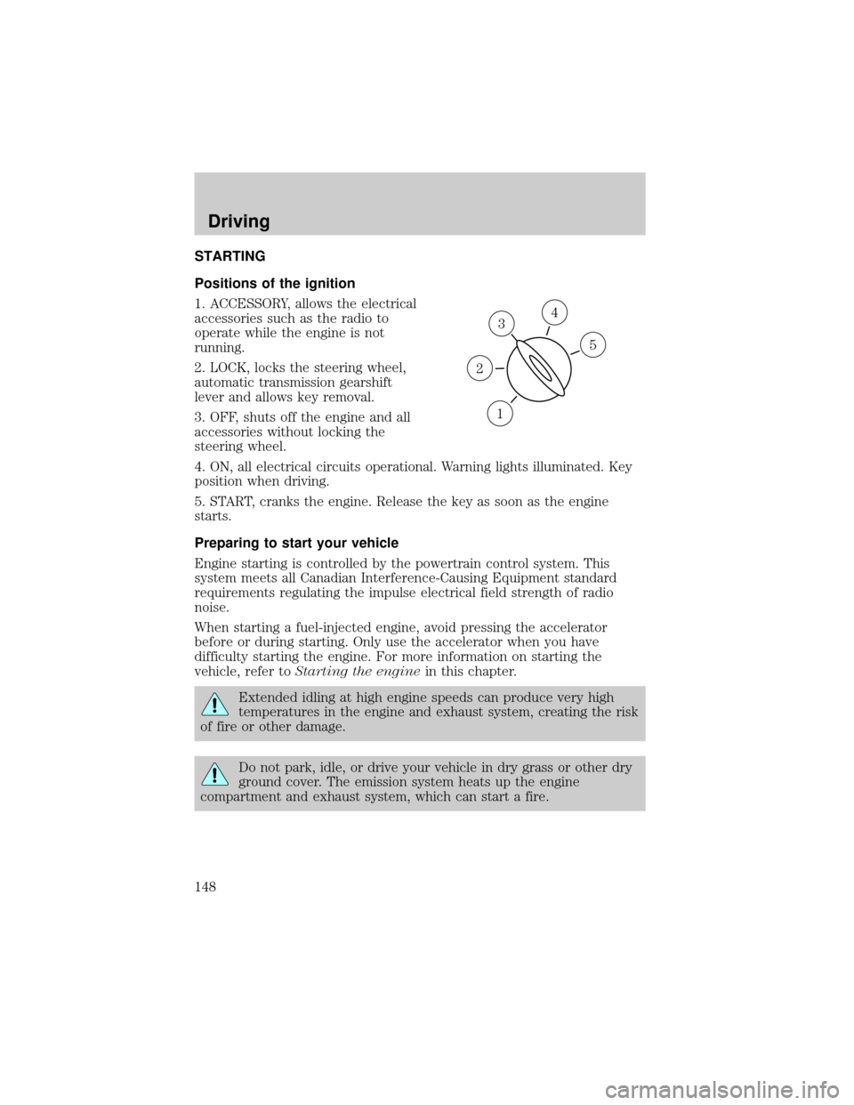
Positions of the ignition
1. ACCESSORY, allows the electrical
accessories such as the radio to
operate while the engine is not
running.
2. LOCK, locks the steering wheel,
automatic transmission gearshift
lever and allows key removal.
3. OFF, shuts off the engine and all
accessories without locking the
steering wheel.
4. ON, all electrical circuits operational. Warning lights illuminated. Key
position when driving.
5. START, cranks the engine. Release the key as soon as the engine
starts.
Preparing to start your vehicle
Engine starting is controlled by the powertrain control system. This
system meets all Canadian Interference-Causing Equipment standard
requirements regulating the impulse electrical field strength of radio
noise.
When starting a fuel-injected engine, avoid pressing the accelerator
before or during starting. Only use the accelerator when you have
difficulty starting the engine. For more information on starting the
vehicle, refer toStarting the enginein this chapter.
Extended idling at high engine speeds can produce very high
temperatures in the engine and exhaust system, creating the risk
of fire or other damage.
Do not park, idle, or drive your vehicle in dry grass or other dry
ground cover. The emission system heats up the engine
compartment and exhaust system, which can start a fire.
3
1
2
5
4
Driving
148
Page 150 of 272
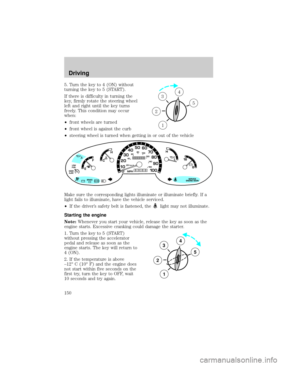
5. Turn the key to 4 (ON) without
turning the key to 5 (START).
If there is difficulty in turning the
key, firmly rotate the steering wheel
left and right until the key turns
freely. This condition may occur
when:
²front wheels are turned
²front wheel is against the curb
²steering wheel is turned when getting in or out of the vehicle
Make sure the corresponding lights illuminate or illuminate briefly. If a
light fails to illuminate, have the vehicle serviced.
²If the driver's safety belt is fastened, the
light may not illuminate.
Starting the engine
Note:Whenever you start your vehicle, release the key as soon as the
engine starts. Excessive cranking could damage the starter.
1. Turn the key to 5 (START)
without pressing the accelerator
pedal and release as soon as the
engine starts. The key will return to
4 (ON).
2. If the temperature is above
±12É C (10É F) and the engine does
not start within five seconds on the
first try, turn the key to OFF, wait
10 seconds and try again.
1
2
34
5
3
2
1
5
4
Driving
150
Page 153 of 272
in the steering wheel while braking, the vehicle should be inspected by a
qualified service technician.
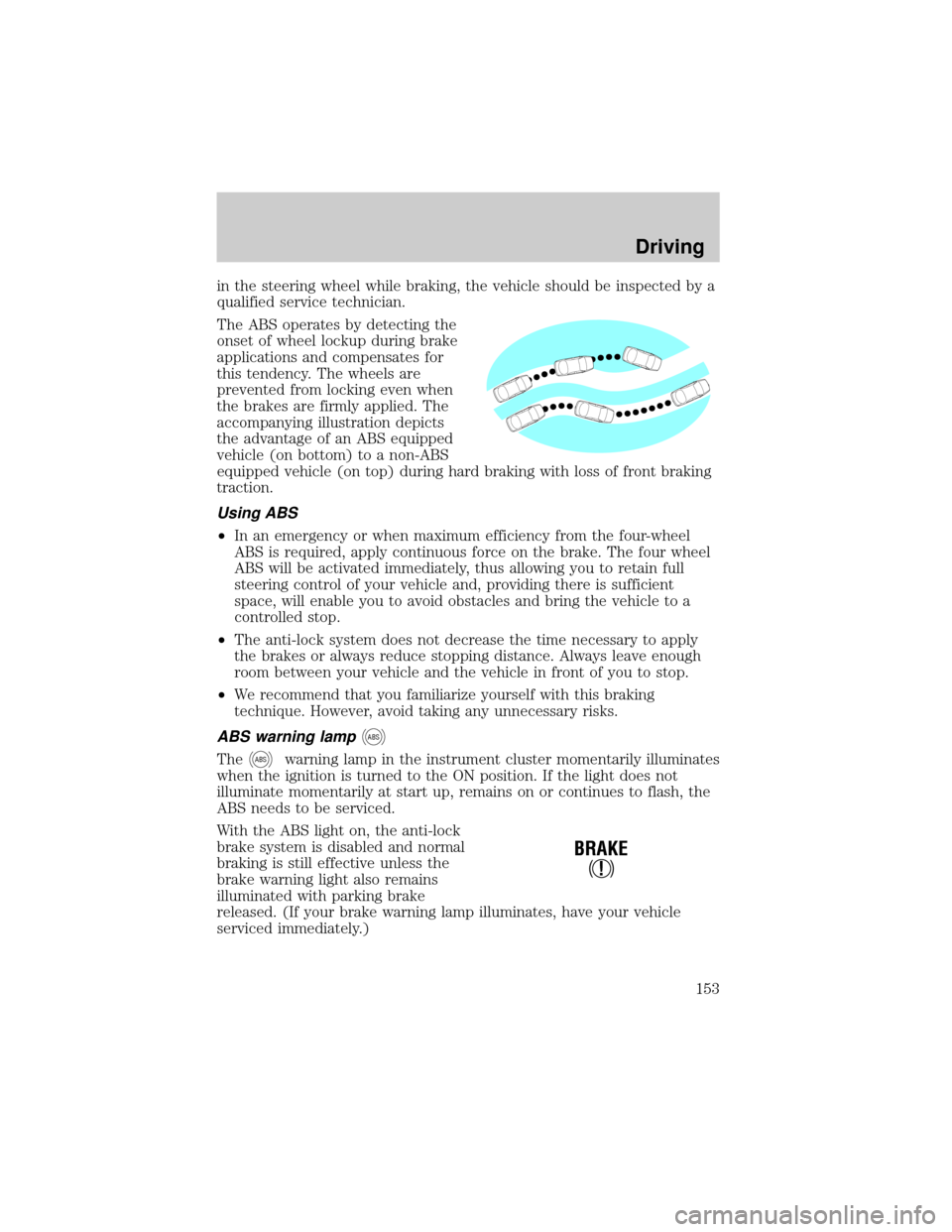
The ABS operates by detecting the
onset of wheel lockup during brake
applications and compensates for
this tendency. The wheels are
prevented from locking even when
the brakes are firmly applied. The
accompanying illustration depicts
the advantage of an ABS equipped
vehicle (on bottom) to a non-ABS
equipped vehicle (on top) during hard braking with loss of front braking
traction.
Using ABS
²In an emergency or when maximum efficiency from the four-wheel
ABS is required, apply continuous force on the brake. The four wheel
ABS will be activated immediately, thus allowing you to retain full
steering control of your vehicle and, providing there is sufficient
space, will enable you to avoid obstacles and bring the vehicle to a
controlled stop.
²The anti-lock system does not decrease the time necessary to apply
the brakes or always reduce stopping distance. Always leave enough
room between your vehicle and the vehicle in front of you to stop.
²We recommend that you familiarize yourself with this braking
technique. However, avoid taking any unnecessary risks.
ABS warning lampABS
TheABSwarning lamp in the instrument cluster momentarily illuminates
when the ignition is turned to the ON position. If the light does not
illuminate momentarily at start up, remains on or continues to flash, the
ABS needs to be serviced.
With the ABS light on, the anti-lock
brake system is disabled and normal
braking is still effective unless the
brake warning light also remains
illuminated with parking brake
released. (If your brake warning lamp illuminates, have your vehicle
serviced immediately.)
!
BRAKE
Driving
153
Page 155 of 272
STEERING
Your vehicle is equipped with power steering. Power steering uses energy
from the engine to help steer the vehicle.
To prevent damage to the power steering pump:
²Never hold the steering wheel to the extreme right or the extreme left
for more than a few seconds when the engine is running.
²Do not operate the vehicle with a low power steering pump fluid level
(below the MIN mark on the reservoir).
If the power steering system breaks down (or if the engine is turned
off), you can steer the vehicle manually, but it takes more effort.
If the steering wanders or pulls, the condition could be caused by any of
the following:
²underinflated tire(s) on any wheel(s)
²uneven vehicle loading
²high crown in center of road
²high crosswinds
²wheels out of alignment
²loose or worn suspension components
TRACTION-LOK AXLE (IF EQUIPPED)
This axle provides added traction on slippery surfaces, particularly when
one wheel is on a poor traction surface. Under normal conditions, the
Traction-Lok axle functions like a standard rear axle.
Extended use of other than the manufacturer's specified size tires on a
Traction-Lok rear axle could result in a permanent reduction in
effectiveness. This loss of effectiveness does not affect normal driving
and should not be noticeable to the driver.
To avoid injury, never run the engine with one wheel off the
ground, such as when changing a tire.
Driving
155
Page 178 of 272
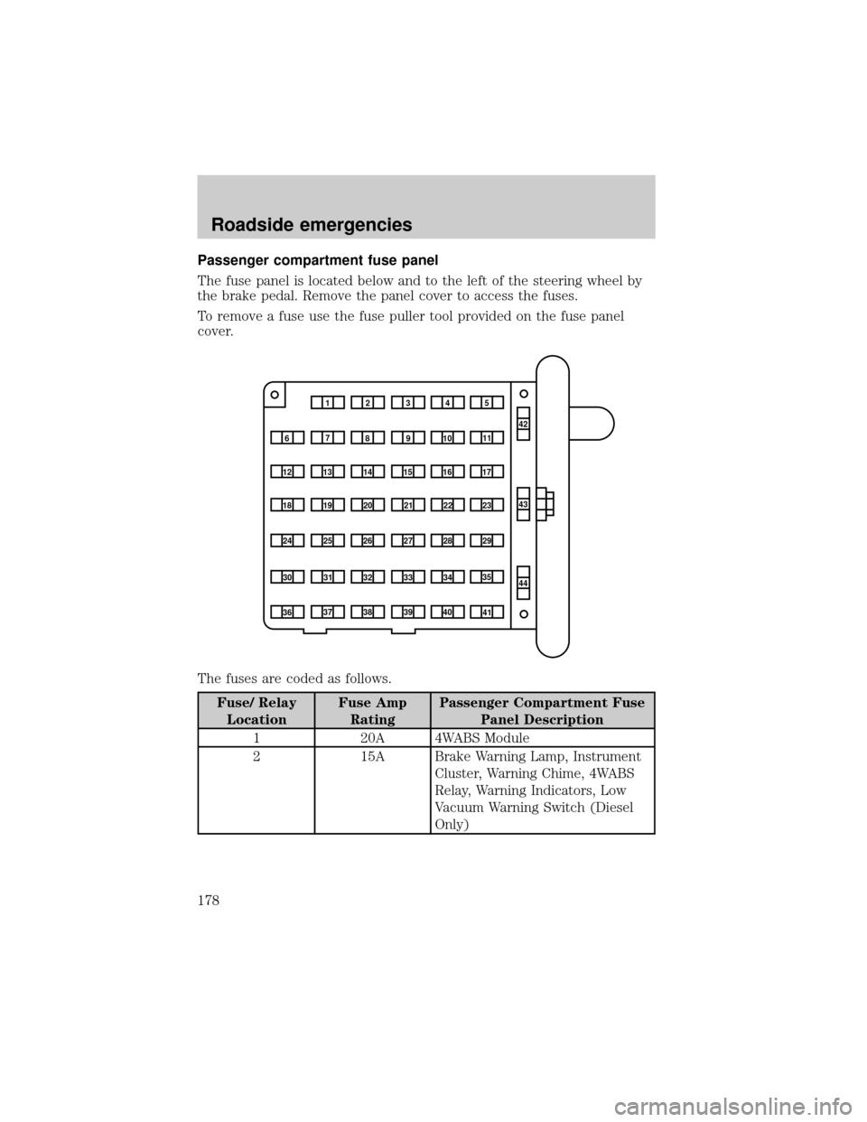
Passenger compartment fuse panel
The fuse panel is located below and to the left of the steering wheel by
the brake pedal. Remove the panel cover to access the fuses.
To remove a fuse use the fuse puller tool provided on the fuse panel
cover.
The fuses are coded as follows.
Fuse/ Relay
LocationFuse Amp
RatingPassenger Compartment Fuse
Panel Description
1 20A 4WABS Module
2 15A Brake Warning Lamp, Instrument
Cluster, Warning Chime, 4WABS
Relay, Warning Indicators, Low
Vacuum Warning Switch (Diesel
Only)
1234
5
7
689101142
43
44 13 12 14
15 16 17
19 18
2021 22 23
25 24
26 27 28 29
31 30 32 33 3435
37
3638 3940
41
Roadside emergencies
178
Page 184 of 272
Fuse/Relay
LocationFuse Amp
RatingPower Distribution Box
Description
H Ð Blower Motor Relay
J Ð Horn Relay
K Ð Fuel Pump Relay
* Mini Fuses ** Maxi Fuses
Relays
Relays are located in the power distribution box and should be replaced
by qualified technicians.
CHANGING THE TIRES
If you get a flat tire while driving, do not apply the brake heavily.
Instead, gradually decrease your speed. Hold the steering wheel firmly
and slowly move to a safe place on the side of the road.
Spare tire information
The spare tire for your vehicle is stowed under the rear of your vehicle
(except cutaway and stripped chassis models).
To remove the spare tire:
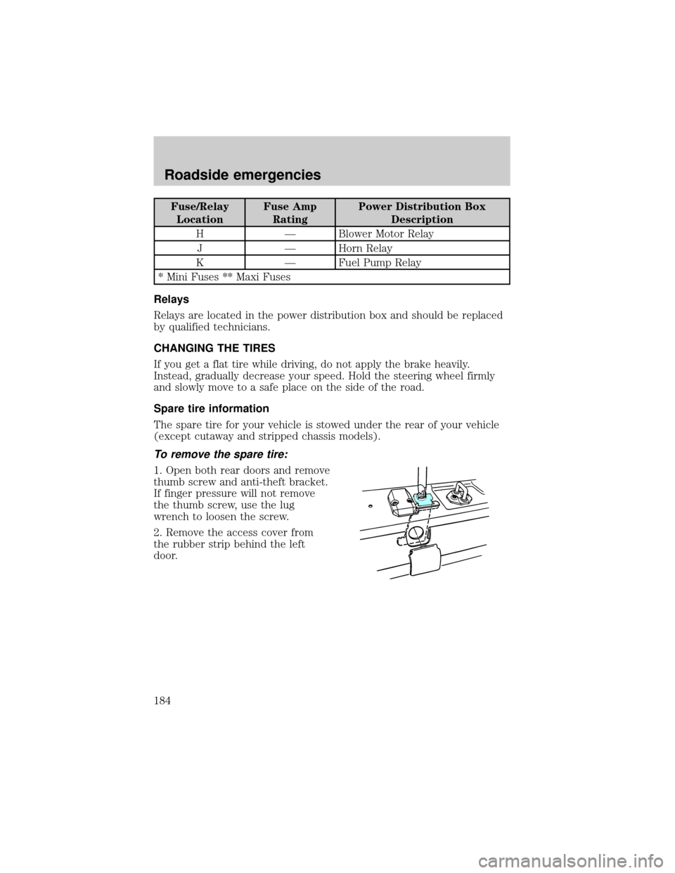
1. Open both rear doors and remove
thumb screw and anti-theft bracket.
If finger pressure will not remove
the thumb screw, use the lug
wrench to loosen the screw.
2. Remove the access cover from
the rubber strip behind the left
door.
Roadside emergencies
184
Page 189 of 272
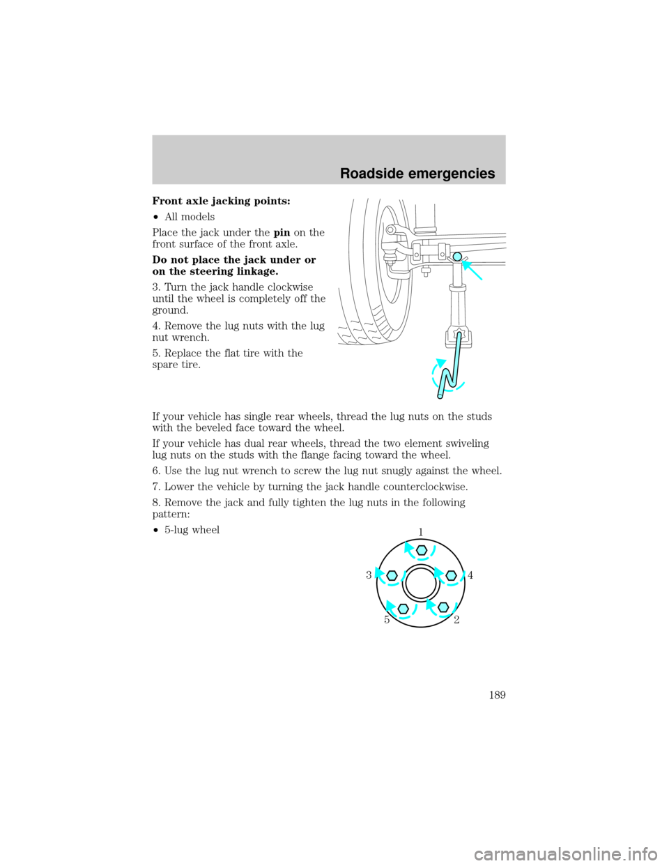
Front axle jacking points:
²All models
Place the jack under thepinon the
front surface of the front axle.
Do not place the jack under or
on the steering linkage.
3. Turn the jack handle clockwise
until the wheel is completely off the
ground.
4. Remove the lug nuts with the lug
nut wrench.
5. Replace the flat tire with the
spare tire.
If your vehicle has single rear wheels, thread the lug nuts on the studs
with the beveled face toward the wheel.
If your vehicle has dual rear wheels, thread the two element swiveling
lug nuts on the studs with the flange facing toward the wheel.
6. Use the lug nut wrench to screw the lug nut snugly against the wheel.
7. Lower the vehicle by turning the jack handle counterclockwise.
8. Remove the jack and fully tighten the lug nuts in the following
pattern:
²5-lug wheel
1
4 3
2 5
Roadside emergencies
189