FORD E SERIES 2024 Owners Manual
Manufacturer: FORD, Model Year: 2024, Model line: E SERIES, Model: FORD E SERIES 2024Pages: 303, PDF Size: 6.95 MB
Page 121 of 303
See Troubleshooting for additionalinformation.
Green: Indicates that the system isavailable or ready to provide a warning onthe indicated side(s).
Red: Indicates that the system is providingor has just provided a lane keeping alertwarning.
You can temporarily disable the system atany time by doing the following:
•Quick braking.
•Fast acceleration.
•Using your direction indicator.
•Evasive steering maneuver.
•Driving too close to the lane markings.
Troubleshooting
Why is the feature not available (line markings are gray) when I can see the lane markingson the road?
Your vehicle speed is outside the operational range of the feature.
The sun is shining directly into the camera lens.
A quick intentional lane change has occurred.
Your vehicle stays too close to the lane markings.
Driving at high speeds in curves.
The last feature activation occurred a short time ago.
Ambiguous lane markings, for example in construction zones.
Rapid transition from light to dark, or from dark to light.
Sudden offset in lane markings.
ABS or AdvanceTrac™ is active.
There is a camera blockage due to dirt, grime, fog, frost or water on the windshield.
You are driving too close to the vehicle in front of you.
Transitioning between no lane markings to lane markings or vice versa.
There is standing water on the road.
Faint lane markings, for example partial yellow lane markings on concrete roads.
Lane width is too narrow or too wide.
No one calibrated the camera after replacing the windshield.
Driving on tight roads or on uneven roads.
Vehicle accessories are blocking the camera, for example a snowplow.
117
2024 E-Series (TE4) Canada/United States of America, enUSA, Edition date: 202210, First-PrintingDriving Aids
Page 122 of 303
STEERING
Hydraulic Power Steering
To help prevent damage to the powersteering system:
•Do not hold the steering wheel at itsfurthest turning points for more thanthree to five seconds when the engineis running.
•Avoid continuously steering back andforth with elevated engine RPM as thismay overheat the system. If trying tofree a stuck vehicle, pause betweenattempts to allow the power steeringsystem to cool or seek assistance.Typical steering and driving maneuversallow the system to cool.
•Do not operate the vehicle if the powersteering pump fluid level is below theMIN mark on the reservoir.
•Some noise is normal during operation.If excessive, check for low powersteering pump fluid level beforeseeking service by your dealer.
•Heavy or uneven efforts may be causedby low power steering fluid. Check forlow power steering pump fluid levelbefore seeking service by your dealer.
•Do not fill the power steering pumpreservoir above the MAX mark on thereservoir, as this may result in leaksfrom the reservoir.
If the power steering system breaks downor if you switch the engine off, you cansteer the vehicle manually, but it takesmore effort.
If you have any steering componentsserviced or replaced, install new fasteners.Many fasteners have coatings with threadadhesive, or have prevailing torquefeatures you cannot reuse. Do not reuse abolt or nut. Torque fasteners tospecifications.
Steering Tips
If the steering wanders or pulls, check for:
•An improperly inflated tire.
•Uneven tire wear.
•Loose or worn suspensioncomponents.
•Loose or worn steering components.
•Improper vehicle alignment.
Note:A high crown in the road or highcrosswinds may also make the steeringseem to wander or pull.
PRE-COLLISION ASSIST (IF
EQUIPPED)
WARNING: You are responsible forcontrolling your vehicle at all times. Thesystem is designed to be an aid and doesnot relieve you of your responsibility todrive with due care and attention. Failureto follow this instruction could result inthe loss of control of your vehicle,personal injury or death.
WARNING: The system does notoperate during hard acceleration orsteering. Failure to take care may leadto a crash or personal injury.
WARNING: The system mayoperate with reduced function duringcold and inclement weather conditions.Snow, ice, rain, spray and fog canadversely affect the system. Keep thefront camera and radar free of snow andice. Failure to follow this instruction mayresult in the loss of control of yourvehicle, serious personal injury or death.
118
2024 E-Series (TE4) Canada/United States of America, enUSA, Edition date: 202210, First-PrintingDriving Aids
Page 123 of 303
WARNING: Some situations andobjects prevent hazard detection. Forexample low or direct sunlight, inclementweather, unconventional vehicle types,and pedestrians. Apply the brakes whennecessary. Failure to follow thisinstruction could result in the loss ofcontrol of your vehicle, personal injury ordeath.
WARNING: Take additional care ifyour vehicle is heavily loaded or you aretowing a trailer. These conditions couldresult in reduced performance of thissystem. Failure to follow this instructioncould result in the loss of control of yourvehicle, personal injury or death.
WARNING: The system cannothelp prevent all crashes. Do not rely onthis system to replace driver judgmentand the need to maintain a safe distanceand speed.
Using the Pre-Collision AssistSystem
The pre-collision assist system is active atspeeds above 3 mph (5 km/h). Pedestriandetection functions at speeds up to50 mph (80 km/h).
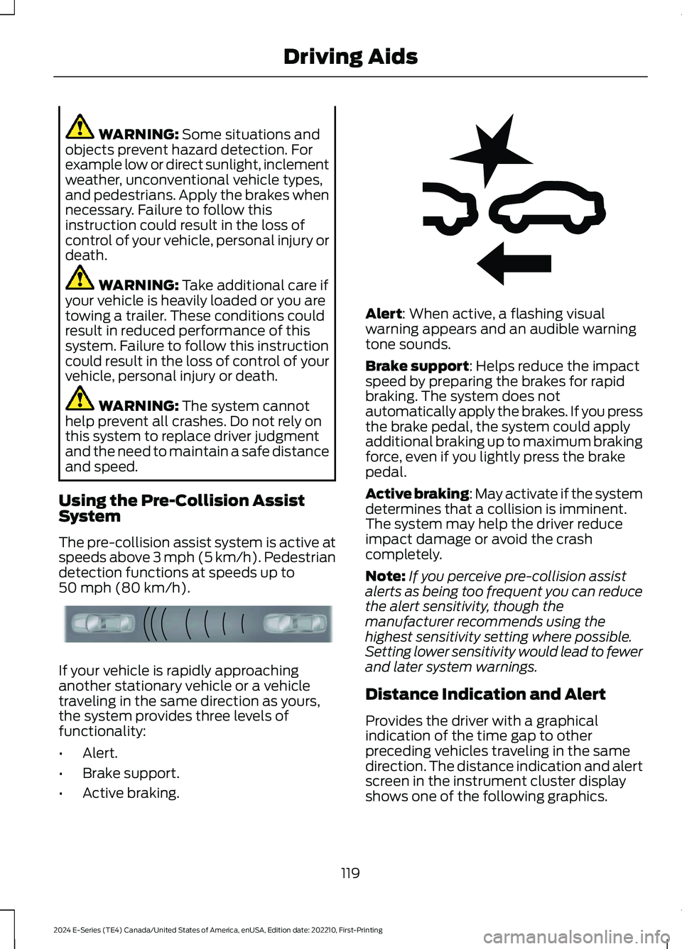
If your vehicle is rapidly approachinganother stationary vehicle or a vehicletraveling in the same direction as yours,the system provides three levels offunctionality:
•Alert.
•Brake support.
•Active braking.
Alert: When active, a flashing visualwarning appears and an audible warningtone sounds.
Brake support: Helps reduce the impactspeed by preparing the brakes for rapidbraking. The system does notautomatically apply the brakes. If you pressthe brake pedal, the system could applyadditional braking up to maximum brakingforce, even if you lightly press the brakepedal.
Active braking: May activate if the systemdetermines that a collision is imminent.The system may help the driver reduceimpact damage or avoid the crashcompletely.
Note:If you perceive pre-collision assistalerts as being too frequent you can reducethe alert sensitivity, though themanufacturer recommends using thehighest sensitivity setting where possible.Setting lower sensitivity would lead to fewerand later system warnings.
Distance Indication and Alert
Provides the driver with a graphicalindication of the time gap to otherpreceding vehicles traveling in the samedirection. The distance indication and alertscreen in the instrument cluster displayshows one of the following graphics.
119
2024 E-Series (TE4) Canada/United States of America, enUSA, Edition date: 202210, First-PrintingDriving AidsE156130 E255268
Page 124 of 303
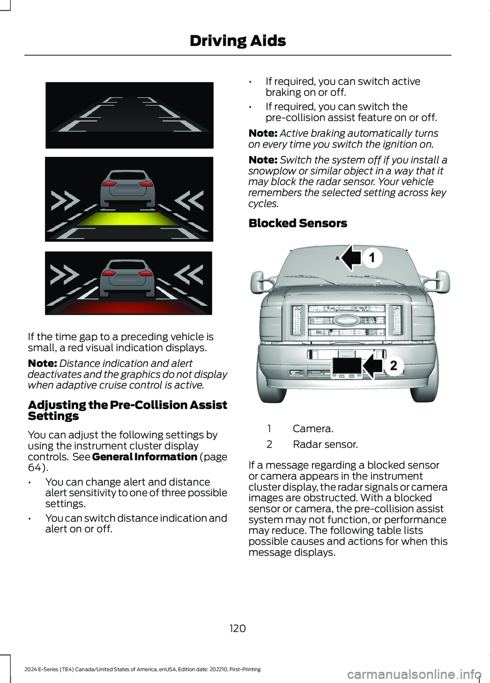
If the time gap to a preceding vehicle issmall, a red visual indication displays.
Note:Distance indication and alertdeactivates and the graphics do not displaywhen adaptive cruise control is active.
Adjusting the Pre-Collision AssistSettings
You can adjust the following settings byusing the instrument cluster displaycontrols. See General Information (page64).
•You can change alert and distancealert sensitivity to one of three possiblesettings.
•You can switch distance indication andalert on or off.
•If required, you can switch activebraking on or off.
•If required, you can switch thepre-collision assist feature on or off.
Note:Active braking automatically turnson every time you switch the ignition on.
Note:Switch the system off if you install asnowplow or similar object in a way that itmay block the radar sensor. Your vehicleremembers the selected setting across keycycles.
Blocked Sensors
Camera.1
Radar sensor.2
If a message regarding a blocked sensoror camera appears in the instrumentcluster display, the radar signals or cameraimages are obstructed. With a blockedsensor or camera, the pre-collision assistsystem may not function, or performancemay reduce. The following table listspossible causes and actions for when thismessage displays.
120
2024 E-Series (TE4) Canada/United States of America, enUSA, Edition date: 202210, First-PrintingDriving AidsE254791 E310549
Page 125 of 303
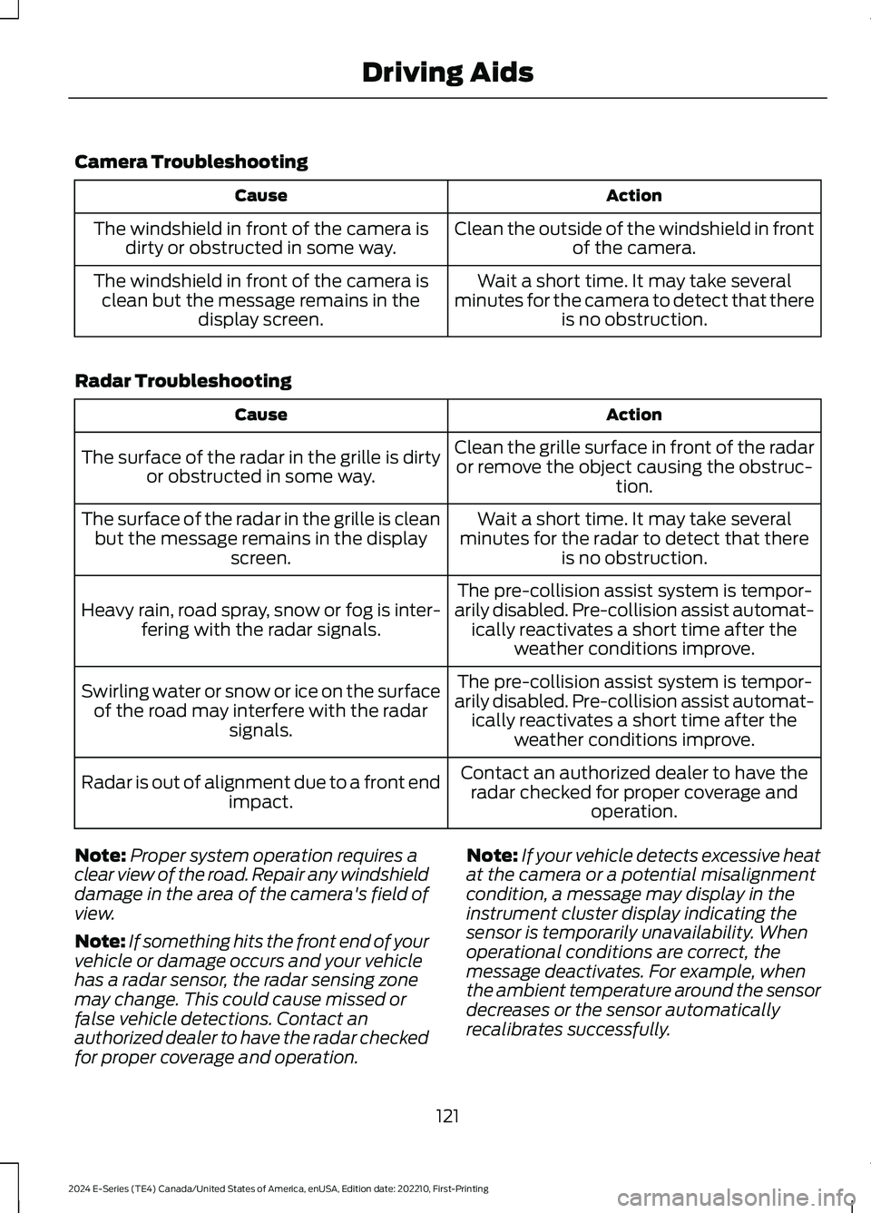
Camera Troubleshooting
ActionCause
Clean the outside of the windshield in frontof the camera.The windshield in front of the camera isdirty or obstructed in some way.
Wait a short time. It may take severalminutes for the camera to detect that thereis no obstruction.
The windshield in front of the camera isclean but the message remains in thedisplay screen.
Radar Troubleshooting
ActionCause
Clean the grille surface in front of the radaror remove the object causing the obstruc-tion.
The surface of the radar in the grille is dirtyor obstructed in some way.
Wait a short time. It may take severalminutes for the radar to detect that thereis no obstruction.
The surface of the radar in the grille is cleanbut the message remains in the displayscreen.
The pre-collision assist system is tempor-arily disabled. Pre-collision assist automat-ically reactivates a short time after theweather conditions improve.
Heavy rain, road spray, snow or fog is inter-fering with the radar signals.
The pre-collision assist system is tempor-arily disabled. Pre-collision assist automat-ically reactivates a short time after theweather conditions improve.
Swirling water or snow or ice on the surfaceof the road may interfere with the radarsignals.
Contact an authorized dealer to have theradar checked for proper coverage andoperation.
Radar is out of alignment due to a front endimpact.
Note:Proper system operation requires aclear view of the road. Repair any windshielddamage in the area of the camera's field ofview.
Note:If something hits the front end of yourvehicle or damage occurs and your vehiclehas a radar sensor, the radar sensing zonemay change. This could cause missed orfalse vehicle detections. Contact anauthorized dealer to have the radar checkedfor proper coverage and operation.
Note:If your vehicle detects excessive heatat the camera or a potential misalignmentcondition, a message may display in theinstrument cluster display indicating thesensor is temporarily unavailability. Whenoperational conditions are correct, themessage deactivates. For example, whenthe ambient temperature around the sensordecreases or the sensor automaticallyrecalibrates successfully.
121
2024 E-Series (TE4) Canada/United States of America, enUSA, Edition date: 202210, First-PrintingDriving Aids
Page 126 of 303
LOAD LIMIT
Vehicle Loading - with andwithout a Trailer
This section guides you in theproper loading of your vehicle,trailer, or both. Keep your loadedvehicle weight within its designrating capability, with or withouta trailer. Properly loading yourvehicle provides maximum returnof vehicle design performance.Before you load your vehicle,become familiar with thefollowing terms for determiningyour vehicle’s weight rating, withor without a trailer, from thevehicle’s Tire and LoadingInformation label or SafetyCompliance Certification label.
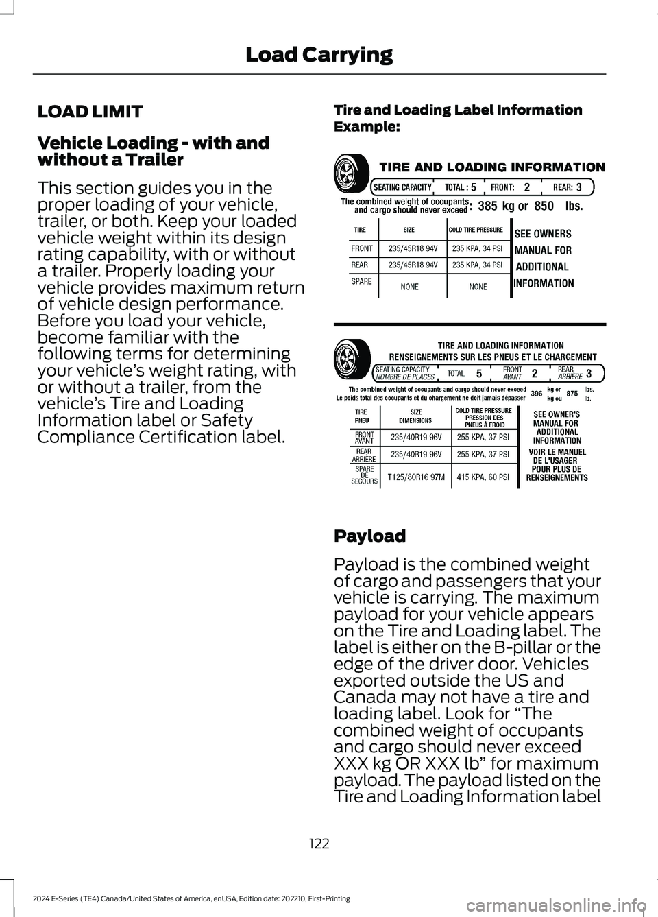
Tire and Loading Label InformationExample:
Payload
Payload is the combined weightof cargo and passengers that yourvehicle is carrying. The maximumpayload for your vehicle appearson the Tire and Loading label. Thelabel is either on the B-pillar or theedge of the driver door. Vehiclesexported outside the US andCanada may not have a tire andloading label. Look for “Thecombined weight of occupantsand cargo should never exceedXXX kg OR XXX lb” for maximumpayload. The payload listed on theTire and Loading Information label
122
2024 E-Series (TE4) Canada/United States of America, enUSA, Edition date: 202210, First-PrintingLoad CarryingE198719
Page 127 of 303
is the maximum payload for yourvehicle as built by the assemblyplant. If you install any additionalequipment on your vehicle, youmust determine the new payload.Subtract the weight of theequipment from the payload listedon the Tire and Loading label.When towing, trailer tongueweight or king pin weight is alsopart of payload.
WARNING: Theappropriate loading capacity ofyour vehicle can be limited eitherby volume capacity (how muchspace is available) or by payloadcapacity (how much weight thevehicle should carry). Once youhave reached the maximumpayload of your vehicle, do notadd more cargo, even if there isspace available. Overloading orimproperly loading your vehiclecan contribute to loss of vehiclecontrol and vehicle rollover.
GAWR (Gross Axle WeightRating)
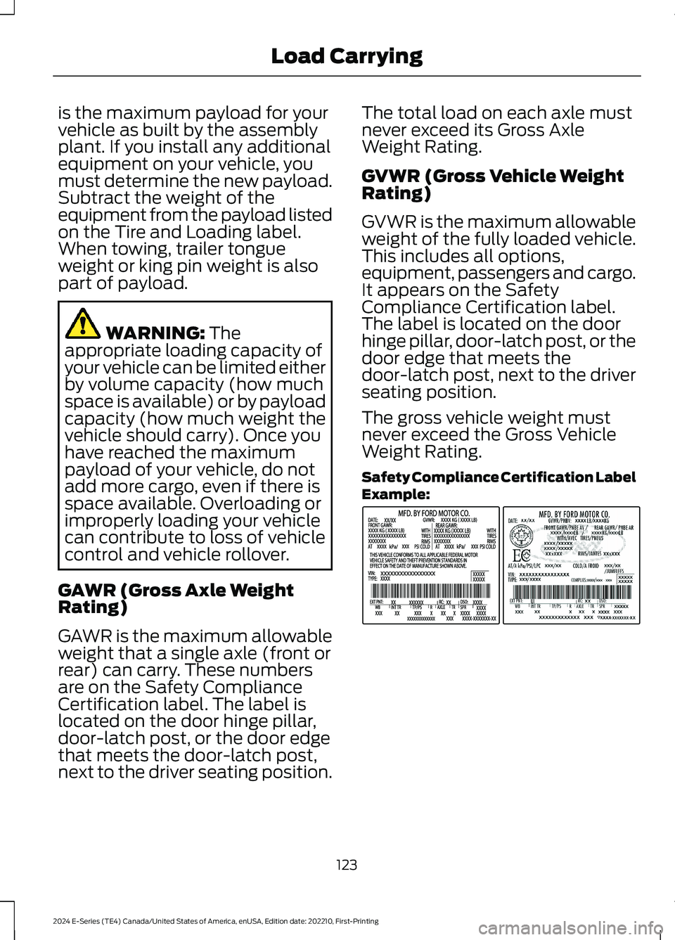
GAWR is the maximum allowableweight that a single axle (front orrear) can carry. These numbersare on the Safety ComplianceCertification label. The label islocated on the door hinge pillar,door-latch post, or the door edgethat meets the door-latch post,next to the driver seating position.
The total load on each axle mustnever exceed its Gross AxleWeight Rating.
GVWR (Gross Vehicle WeightRating)
GVWR is the maximum allowableweight of the fully loaded vehicle.This includes all options,equipment, passengers and cargo.It appears on the SafetyCompliance Certification label.The label is located on the doorhinge pillar, door-latch post, or thedoor edge that meets thedoor-latch post, next to the driverseating position.
The gross vehicle weight mustnever exceed the Gross VehicleWeight Rating.
Safety Compliance Certification LabelExample:
123
2024 E-Series (TE4) Canada/United States of America, enUSA, Edition date: 202210, First-PrintingLoad CarryingE198828
Page 128 of 303
WARNING: Exceeding theSafety Compliance Certificationlabel vehicle weight limits canadversely affect theperformance and handling ofyour vehicle, cause vehicledamage and can result in theloss of control of your vehicle,serious personal injury or death.
Maximum Loaded TrailerWeight
Maximum loaded trailer weight isthe highest possible weight of afully loaded trailer the vehicle cantow. Consult an authorized dealer(or the RV and Trailer TowingGuide available at an authorizeddealer) for more detailed
information.
GCWR (Gross CombinedWeight Rating)
GCWR is the maximum allowableweight of the vehicle and theloaded trailer, including all cargoand passengers, that the vehiclecan handle without riskingdamage. (Important: The towingvehicle’s braking system is ratedfor operation at Gross Vehicle
Weight Rating, not at GrossCombined Weight Rating.)Separate functional brakes should
be used for safe control of towedvehicles and for trailers where theGross Combined Weight of thetowing vehicle plus the trailerexceed the Gross Vehicle WeightRating of the towing vehicle.
The gross combined weight mustnever exceed the Gross CombinedWeight Rating.
Note: For trailer towinginformation refer to the RV andTrailer Towing Guide available atan authorized dealer.
WARNING: Do not exceedthe GVWR or the GAWRspecified on the certificationlabel.
WARNING: Do not usereplacement tires with lowerload carrying capacities than theoriginal tires because they maylower your vehicle's GVWR andGAWR limitations. Replacementtires with a higher limit than theoriginal tires do not increase theGVWR and GAWR limitations.
WARNING: Exceeding anyvehicle weight rating canadversely affect theperformance and handling ofyour vehicle, cause vehicledamage and can result in theloss of control of your vehicle,serious personal injury or death.
124
2024 E-Series (TE4) Canada/United States of America, enUSA, Edition date: 202210, First-PrintingLoad Carrying
Page 129 of 303
Steps for determining thecorrect load limit:
1.Locate the statement "Thecombined weight of occupantsand cargo should never exceedXXX kg or XXX lb." on yourvehicle’s placard.
2.Determine the combinedweight of the driver andpassengers that will be ridingin your vehicle.
3.Subtract the combined weightof the driver and passengersfrom XXX kg or XXX lb.
4.The resulting figure equals theavailable amount of cargo andluggage load capacity. Forexample, if the “XXX” amountequals 1,400 lb. and there willbe five 150 lb. passengers inyour vehicle, the amount ofavailable cargo and luggageload capacity is 650 lb.(1400-(5 x 150) = 1400-750 =650 lb.)
5.Determine the combinedweight of luggage and cargobeing loaded on the vehicle.That weight may not safelyexceed the available cargo andluggage load capacitycalculated in Step 4.
6.If your vehicle will be towing atrailer, load from your trailerwill be transferred to yourvehicle. Consult this manual todetermine how this reduces the
available cargo and luggageload capacity of your vehicle.
Helpful examples for calculatingthe available amount of cargoand luggage load capacity
Suppose your vehicle has a1400-pound (635-kilogram) cargoand luggage capacity. You decideto go golfing. Is there enough loadcapacity to carry you, four of yourfriends and all the golf bags? Youand four friends average 220pounds (99 kilograms) each andthe golf bags weigh approximately30 pounds (13.5 kilograms) each.The calculation would be: 1400 -(5 x 220) - (5 x 30) = 1400 - 1100- 150 = 150 pounds. Yes, you haveenough load capacity in yourvehicle to transport four friendsand your golf bags. In metric units,the calculation would be: 635kilograms - (5 x 99 kilograms) -(5 x 13.5 kilograms) = 635 - 495 -67.5 = 72.5 kilograms.
Suppose your vehicle has a1400-pound (635-kilogram) cargoand luggage capacity. You andone of your friends decide to pickup cement from the local homeimprovement store to finish thatpatio you have been planning forthe past two years. Measuring theinside of the vehicle with the rearseat folded down, you have roomfor twelve 100-pound(45-kilogram) bags of cement. Doyou have enough load capacity totransport the cement to yourhome? If you and your friend eachweigh 220 pounds (99 kilograms),
the calculation would be: 1400 -(2 x 220) - (12 x 100) = 1400 - 440
125
2024 E-Series (TE4) Canada/United States of America, enUSA, Edition date: 202210, First-PrintingLoad Carrying
Page 130 of 303
- 1200 = - 240 pounds. No, you donot have enough cargo capacityto carry that much weight. Inmetric units, the calculation wouldbe: 635 kilograms - (2 x 99kilograms) - (12 x 45 kilograms) =635 - 198 - 540 = -103 kilograms.You will need to reduce the loadweight by at least 240 pounds(104 kilograms). If you removethree 100-pound (45-kilogram)cement bags, then the loadcalculation would be:1400 - (2 x220) - (9 x 100) = 1400 - 440 -900 = 60 pounds. Now you havethe load capacity to transport thecement and your friend home. Inmetric units, the calculation wouldbe: 635 kilograms - (2 x 99kilograms) - (9 x 45 kilograms) =635 - 198 - 405 = 32 kilograms.
The above calculations alsoassume that the loads arepositioned in your vehicle in amanner that does not overloadthe front or the rear gross axleweight rating specified for yourvehicle on the Safety ComplianceCertification label.
Special Loading Instructionsfor Owners of Pick-up Trucksand Utility-type Vehicles
WARNING: When loadingthe roof racks, we recommendyou evenly distribute the load,as well as maintain a low centerof gravity. Loaded vehicles, withhigher centers of gravity, may
handle differently than unloadedvehicles. Take extra precautions,such as slower speeds andincreased stopping distance,when driving a heavily loadedvehicle.
126
2024 E-Series (TE4) Canada/United States of America, enUSA, Edition date: 202210, First-PrintingLoad Carrying