FORD E SERIES 2024 Owners Manual
Manufacturer: FORD, Model Year: 2024, Model line: E SERIES, Model: FORD E SERIES 2024Pages: 303, PDF Size: 6.95 MB
Page 221 of 303
3.Cycle the ignition to the on positionwith the engine off.
4.Turn the hazard flashers on then offthree times. You must accomplish thiswithin 10 seconds. If you successfullyenter the reset mode, the horn soundsonce, the system indicator flashes anda message shows in the informationdisplay. If this does not occur, pleasetry again starting at step 2. If afterrepeated attempts to enter the resetmode, the horn does not sound, thesystem indicator does not flash and nomessage shows in the informationdisplay, have the system checked assoon as possible.
5.Train the tire pressure monitoringsystem sensors in the tires using thefollowing system reset sequencestarting with the left front tire in thefollowing clockwise order: Left front -driver side front tire, Right front -passenger side front tire, Right rear -passenger side rear tire, Left rear -driver side rear tire.
6.Remove the valve cap from the valvestem on the left front tire. Decrease theair pressure until the horn sounds.
Note:The single horn tone confirms thatthe sensor identification code has beenlearned by the module for this position. Ifyou hear a double horn, the reset procedurewas unsuccessful, and you must repeat it.
7.Remove the valve cap from the valvestem on the right front tire. Decreasethe air pressure until the horn sounds.
8.Remove the valve cap from the valvestem on the right rear tire. Decrease theair pressure until the horn sounds.
9.Remove the valve cap from the valvestem on the left rear tire. Decrease theair pressure until the horn sounds.Training is complete after the hornsounds for the last tire trained, driverside rear tire, the system indicatorstops flashing, and a message showsin the information display.
10.Turn the ignition off. If you hear twoshort tones, the reset procedure wasunsuccessful and you must repeat it.If you hear two short beeps when theignition is off after repeating theprocedure, have the system checkedas soon as possible
11.Set all four tires to the recommendedair pressure as indicated on theSafety Compliance CertificationLabel, affixed to either the door hingepillar, door-latch post, or the dooredge that meets the door-latch post,next to the driver seating position orTire Label located on the B-Pillar orthe edge of the driver door.
Performing the System Reset Procedure- Dual Rear Wheel
For further information seeUnderstanding Your Tire PressureMonitoring System and refer to DualRear Wheel, earlier in this section.
Read the entire procedure beforeattempting.
1.Drive the vehicle above 20 mph(32 km/h) for at least two minutes,then park in a safe location where youcan easily get to all six tires and haveaccess to an air pump.
2.Place the ignition in the off position andkeep the key in the ignition.
3.Cycle the ignition to the on positionwith the engine off.
217
2024 E-Series (TE4) Canada/United States of America, enUSA, Edition date: 202210, First-PrintingWheels and Tires
Page 222 of 303
4.Turn the hazard flashers on then offthree times. You must accomplish thiswithin 10 seconds. If you successfullyenter the reset mode, the horn soundsonce, the system indicator flashes anda message shows in the informationdisplay. If this does not occur, pleasetry again starting at step 2. If afterrepeated attempts to enter the resetmode, the horn does not sound, thesystem indicator does not flash and nomessage shows in the informationdisplay, seek service from yourauthorized dealer.
5.Train the tire pressure monitoringsystem sensors in the tires using thefollowing system reset sequencestarting with the left front tire in thefollowing order: Left front - driver sidefront tire, Right front - passenger sidefront tire, Right outer rear -passengerside rear outer tire, Right inner rear -passenger side rear inner tire, Left outerrear - driver side rear outer tire, Leftinner rear - driver side rear inner tire.
6.Remove the valve cap from the valvestem on the left front tire. Decrease theair pressure until the horn sounds.
Note:The single horn chirp confirms thatthe sensor identification code has beenlearned by the module for this position. If adouble horn is heard, the reset procedurewas unsuccessful, and you must repeat it.
7.Remove the valve cap from the valvestem on the right front tire. Decreasethe air pressure until the horn sounds.
8.Remove the valve cap from the valvestem on the right outer rear tire.Decrease the air pressure until the hornsounds.
9.Remove the valve cap from the valvestem on the right inner rear tire.Decrease the air pressure until the hornsounds.
10.Remove the valve cap from the valvestem on the left outer rear tire.Decrease the air pressure until thehorn sounds.
11.Remove the valve cap from the valvestem on the left inner rear tire.Decrease the air pressure until thehorn sounds. Training is completeafter the horn sounds for the last tiretrained, the system indicator stopsflashing, and a message is shown inthe information display.
12.Turn the ignition off. If two short hornbeeps are heard, the reset procedurewas unsuccessful and you mustrepeat it. If after repeating theprocedure and two short beeps areheard when the ignition is turned tooff, seek assistance from yourauthorized dealer.
13.Set all six tires to the recommendedair pressure as indicated on theSafety Compliance CertificationLabel, affixed to either the door hingepillar, door-latch post, or the dooredge that meets the door-latch post,next to the driver seating position orTire Label located on the B-Pillar orthe edge of the driver door.
CHANGING A ROAD WHEEL
WARNING: To determine therequired pressure(s) for your vehicle, seethe Safety Compliance CertificationLabel (on the door hinge pillar,door-latch post or the door edge thatmeets the door-latch post, next to thedriver seat) or the Tire Label on theB-Pillar or the edge of the driver door.
Note:You should only use tire sealants inroadside emergencies as they may causedamage to the tire pressure monitoringsystem sensor.
218
2024 E-Series (TE4) Canada/United States of America, enUSA, Edition date: 202210, First-PrintingWheels and Tires
Page 223 of 303
Note:The tire pressure monitoring systemindicator light illuminates when the sparetire is in use. To restore the full function ofthe monitoring system, all road wheelsequipped with tire pressure monitoringsensors must be mounted on the vehicle.
Note:Do not use wheels or wheel nutsdifferent than the original equipment, as thismay damage the wheel or mounting system.
If you get a flat tire when driving, do notapply the brake heavily. Instead, graduallydecrease your speed. Hold the steeringwheel firmly and slowly move to a safeplace on the side of the road.
Have a flat serviced by an authorizeddealer to prevent damage to the tirepressure monitoring system sensors. SeeTire Pressure Monitoring System (page213). Replace the spare tire with a road tireas soon as possible. During repairing orreplacing of the flat tire, have theauthorized dealer inspect the tire pressuremonitoring system sensor for damage.
Dissimilar Spare Wheel and TireAssembly Information
WARNING: Failure to follow theseguidelines could result in an increasedrisk of loss of vehicle control, injury ordeath.
If you have a dissimilar spare wheel andtire, then it is intended for temporary useonly. This means that if you need to use it,you should replace it as soon as possiblewith a road wheel and tire assembly thatis the same size and type as the road tiresand wheels that were originally providedby Ford. If the dissimilar spare tire or wheelis damaged, it should be replaced ratherthan repaired.
A dissimilar spare wheel and tire assemblyis defined as a spare wheel and tireassembly that is different in brand, size orappearance from the road tires and wheelsand can be one of three types:
1.T-type mini-spare: This spare tirebegins with the letter T for tire size andmay have Temporary Use Only molded inthe sidewall.
2.Full-size dissimilar spare with labelon wheel: This spare tire has a label onthe wheel that states: THIS WHEEL ANDTIRE ASSEMBLY FOR TEMPORARY USEONLY.
When driving with one of the dissimilarspare tires listed above:
•Do not exceed 50 mph (80 km/h).
•Do not load the vehicle beyondmaximum vehicle load rating listed onthe Safety Compliance Label.
•Do not tow a trailer.
•Do not use snow chains on the end ofthe vehicle with the dissimilar sparetire.
•Do not use more than one dissimilarspare tire at a time.
•Do not use commercial car washingequipment.
•Do not try to repair the dissimilar sparetire.
Using a dissimilar spare wheel and tireassembly can compromise theeffectiveness of the following:
•Handling, stability and brakingperformance.
•Comfort and noise.
•Ground clearance and parking at curbs.
•Winter weather driving capability.
•Wet weather driving capability.
•All-wheel driving capability.
219
2024 E-Series (TE4) Canada/United States of America, enUSA, Edition date: 202210, First-PrintingWheels and Tires
Page 224 of 303
3.Full-size dissimilar spare withoutlabel on wheel
When driving with the full-size dissimilarspare wheel and tire assembly:
•Do not exceed 70 mph (113 km/h).
•Do not use more than one dissimilarspare wheel and tire assembly at atime.
•Do not use commercial car washingequipment.
•Do not use snow chains on the end ofthe vehicle with the dissimilar sparewheel and tire assembly.
Using a dissimilar spare wheel and tireassembly can compromise theeffectiveness of the following :
•Handling, stability and brakingperformance.
•Comfort and noise.
•Ground clearance and parking at curbs.
•Winter weather driving capability.
•Wet weather driving capability.
•All-wheel driving capability.
When driving with the full-size dissimilarspare wheel and tire assembly additionalcaution should be given to:
•Towing a trailer.
•Driving vehicles equipped with acamper body.
•Driving vehicles with a load on thecargo rack.
Drive cautiously when using a full-sizedissimilar spare wheel and tire assemblyand seek service as soon as possible.
Tire Change Procedure (If Equipped)
WARNING: The jack supplied withthis vehicle is only intended for changinga flat tire in an emergency. Do notattempt to do any other work on yourvehicle when it is supported by the jack,as your vehicle could slip off the jack.Failure to follow this instruction couldresult in personal injury or death.
WARNING: To help prevent yourvehicle from moving when changing awheel, shift the transmission into park(P), set the parking brake and use anappropriate block or wheel chock tosecure the wheel diagonally opposite tothe wheel being changed. For example,when changing the front left wheel,place an appropriate block or wheelchock on the right rear wheel.
WARNING: Do not attempt tochange a tire on the side of the vehicleclose to moving traffic. Pull far enoughoff the road to not obstruct the flow oftraffic and avoid the danger of being hitwhen operating the jack or changing thewheel.
WARNING: Only use the jackprovided as original equipment with yourvehicle.
WARNING: The jack supplied withthis vehicle is only intended for changinga flat tire in an emergency. Do notattempt to do any other work on yourvehicle when it is supported by the jack,as your vehicle could slip off the jack.Failure to follow this instruction couldresult in personal injury or death.
WARNING: Only use the jackprovided as original equipment with yourvehicle.
220
2024 E-Series (TE4) Canada/United States of America, enUSA, Edition date: 202210, First-PrintingWheels and Tires
Page 225 of 303
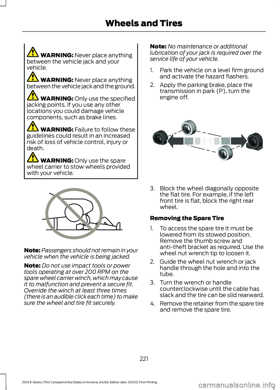
WARNING: Never place anythingbetween the vehicle jack and yourvehicle.
WARNING: Never place anythingbetween the vehicle jack and the ground.
WARNING: Only use the specifiedjacking points. If you use any otherlocations you could damage vehiclecomponents, such as brake lines.
WARNING: Failure to follow theseguidelines could result in an increasedrisk of loss of vehicle control, injury ordeath.
WARNING: Only use the sparewheel carrier to stow wheels providedwith your vehicle.
Note:Passengers should not remain in yourvehicle when the vehicle is being jacked.
Note:Do not use impact tools or powertools operating at over 200 RPM on thespare wheel carrier winch, which may causeit to malfunction and prevent a secure fit.Override the winch at least three times(there is an audible click each time) to makesure the wheel and tire fit securely.
Note:No maintenance or additionallubrication of your jack is required over theservice life of your vehicle.
1.Park the vehicle on a level firm groundand activate the hazard flashers.
2.Apply the parking brake, place thetransmission in park (P), turn theengine off.
3.Block the wheel diagonally oppositethe flat tire. For example, if the leftfront tire is flat, block the right rearwheel.
Removing the Spare Tire
1.To access the spare tire it must belowered from its stowed position.Remove the thumb screw andanti-theft bracket as required. Use thewheel nut wrench tip to loosen it.
2.Guide the wheel nut wrench or jackhandle through the hole and into thetube.
3.Turn the wrench or handlecounterclockwise until the cable hasslack and the tire can be slid rearward.
4.Remove the retainer from the spare tireand remove the spare tire.
221
2024 E-Series (TE4) Canada/United States of America, enUSA, Edition date: 202210, First-PrintingWheels and TiresE166722 E175447
Page 226 of 303
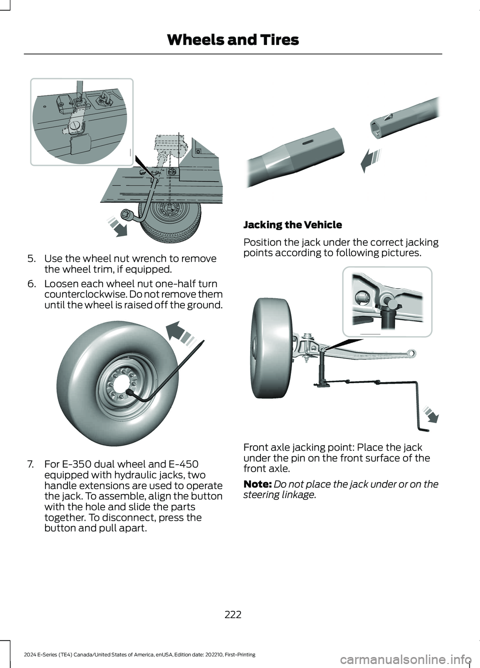
5.Use the wheel nut wrench to removethe wheel trim, if equipped.
6.Loosen each wheel nut one-half turncounterclockwise. Do not remove themuntil the wheel is raised off the ground.
7.For E-350 dual wheel and E-450equipped with hydraulic jacks, twohandle extensions are used to operatethe jack. To assemble, align the buttonwith the hole and slide the partstogether. To disconnect, press thebutton and pull apart.
Jacking the Vehicle
Position the jack under the correct jackingpoints according to following pictures.
Front axle jacking point: Place the jackunder the pin on the front surface of thefront axle.
Note:Do not place the jack under or on thesteering linkage.
222
2024 E-Series (TE4) Canada/United States of America, enUSA, Edition date: 202210, First-PrintingWheels and Tires E366770 E366771 E308882 E366985
Page 227 of 303
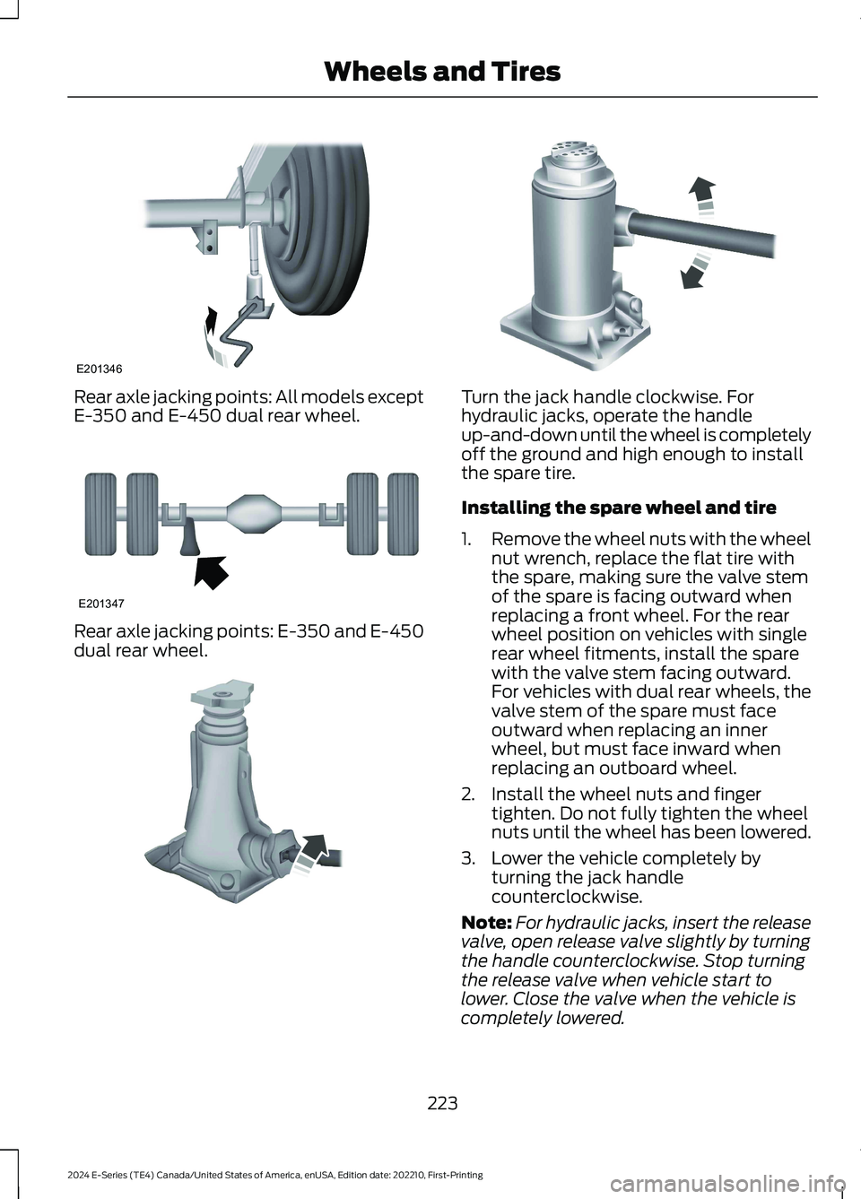
Rear axle jacking points: All models exceptE-350 and E-450 dual rear wheel.
Rear axle jacking points: E-350 and E-450dual rear wheel.
Turn the jack handle clockwise. Forhydraulic jacks, operate the handleup-and-down until the wheel is completelyoff the ground and high enough to installthe spare tire.
Installing the spare wheel and tire
1.Remove the wheel nuts with the wheelnut wrench, replace the flat tire withthe spare, making sure the valve stemof the spare is facing outward whenreplacing a front wheel. For the rearwheel position on vehicles with singlerear wheel fitments, install the sparewith the valve stem facing outward.For vehicles with dual rear wheels, thevalve stem of the spare must faceoutward when replacing an innerwheel, but must face inward whenreplacing an outboard wheel.
2.Install the wheel nuts and fingertighten. Do not fully tighten the wheelnuts until the wheel has been lowered.
3.Lower the vehicle completely byturning the jack handlecounterclockwise.
Note:For hydraulic jacks, insert the releasevalve, open release valve slightly by turningthe handle counterclockwise. Stop turningthe release valve when vehicle start tolower. Close the valve when the vehicle iscompletely lowered.
223
2024 E-Series (TE4) Canada/United States of America, enUSA, Edition date: 202210, First-PrintingWheels and TiresE201346 E201347 E162811 E162819
Page 228 of 303
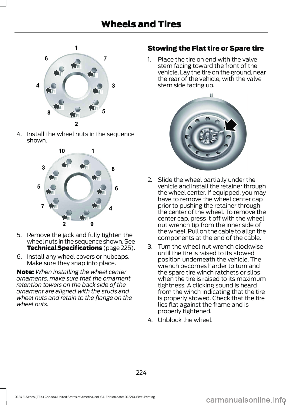
4.Install the wheel nuts in the sequenceshown.
5.Remove the jack and fully tighten thewheel nuts in the sequence shown. SeeTechnical Specifications (page 225).
6.Install any wheel covers or hubcaps.Make sure they snap into place.
Note:When installing the wheel centerornaments, make sure that the ornamentretention towers on the back side of theornament are aligned with the studs andwheel nuts and retain to the flange on thewheel nuts.
Stowing the Flat tire or Spare tire
1.Place the tire on end with the valvestem facing toward the front of thevehicle. Lay the tire on the ground, nearthe rear of the vehicle, with the valvestem side facing up.
2.Slide the wheel partially under thevehicle and install the retainer throughthe wheel center. If equipped, you mayhave to remove the wheel center capprior to pushing the retainer throughthe center of the wheel. To remove thecenter cap, press it off with the wheelnut wrench tip from the inner side ofthe wheel. Pull on the cable to align thecomponents at the end of the cable.
3.Turn the wheel nut wrench clockwiseuntil the tire is raised to its stowedposition underneath the vehicle. Thewrench becomes harder to turn andthe spare tire winch ratchets or slipswhen the tire is raised to its maximumtightness. A clicking sound is heardfrom the winch indicating that the tireis properly stowed. Check that the tirelies flat against the frame and isproperly tightened.
4.Unblock the wheel.
224
2024 E-Series (TE4) Canada/United States of America, enUSA, Edition date: 202210, First-PrintingWheels and Tires13427658E161441 12345678910E169375 E162800
Page 229 of 303
TECHNICAL SPECIFICATIONS
Wheel Lug Nut Torque Specifications
WARNING: When you install a wheel, remove any corrosion, dirt or foreign materialspresent on the mounting surfaces of the wheel or the surface of the wheel hub, brakedrum or brake disc that contacts the wheel. Make sure to secure any fasteners thatattach the rotor to the hub so they do not interfere with the mounting surfaces of thewheel. Installing wheels without following these steps can cause the wheel nuts toloosen and the wheel to come off while your vehicle is in motion, resulting in loss ofvehicle control, personal injury or death.
lb.ft (Nm)1Bolt size
140 lb.ft (190 Nm)9/16 x 18 two-piece lug nut
1 Torque specifications are for nut and bolt threads free of dirt and rust. Use only Fordrecommended replacement fasteners.
On vehicles equipped with single rear wheels, retighten the lug nuts to the specified torqueat 100 miles (160 kilometers) after any wheel disturbance (such as tire rotation, changinga flat tire, wheel removal).
On vehicles equipped with dual rear wheels, retighten the wheel lug nuts to the specifiedtorque at 100 miles (160 kilometers), and again at 500 miles (800 kilometers) of newvehicle operation and after any wheel disturbance (such as tire rotation, changing a flattire, wheel removal).
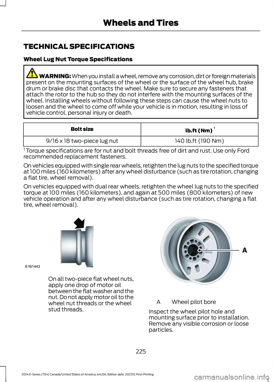
On all two-piece flat wheel nuts,apply one drop of motor oilbetween the flat washer and thenut. Do not apply motor oil to thewheel nut threads or the wheelstud threads.
Wheel pilot boreA
Inspect the wheel pilot hole andmounting surface prior to installation.Remove any visible corrosion or looseparticles.
225
2024 E-Series (TE4) Canada/United States of America, enUSA, Edition date: 202210, First-PrintingWheels and TiresE161443 E145950
Page 230 of 303
ENGINE SPECIFICATIONS
7.3L V8 EngineEngine
445 in³ (7,293 cm³)Displacement.
Minimum 87 octaneRequired fuel.
1-5-4-8-6-3-7-2Firing order.
Coil near spark plug with spark plug wireIgnition system.
0.049 in (1.25 mm) - 0.053 in (1.35 mm)Spark plug gap.
10.5:1Compression ratio.
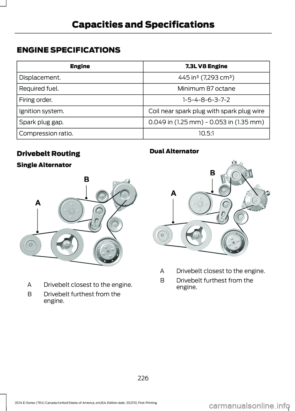
Drivebelt Routing
Single Alternator
Drivebelt closest to the engine.A
Drivebelt furthest from theengine.B
Dual Alternator
Drivebelt closest to the engine.A
Drivebelt furthest from theengine.B
226
2024 E-Series (TE4) Canada/United States of America, enUSA, Edition date: 202210, First-PrintingCapacities and SpecificationsE388771 E388772