ECO mode FORD E SERIES 2024 Owner's Manual
[x] Cancel search | Manufacturer: FORD, Model Year: 2024, Model line: E SERIES, Model: FORD E SERIES 2024Pages: 303, PDF Size: 6.95 MB
Page 213 of 303
FOLLOW THESE MOUNTINGRECOMMENDATIONS
Tire changing can be dangerousand must be done byprofessionally trained personsusing proper tools andprocedures as specified by theUS Tire ManufacturersAssociation (USTMA). Singleor dual assemblies must becompletely deflated beforedemounting.
Your tires should be mounted onwheels of correct size and typeand which are in good, cleancondition. Wheels that are bent,chipped, rusted (steel wheels) orcorroded (alloy wheels) maycause tire damage. The inside ofthe tire must be free from foreignmaterial. Have your retailer checkthe wheels before mounting newtires. Mismatched tires and rimscan explode during mounting.Also, mismatched tires and rimscan result in dangerous tire failureon the road. If a tire is mounted byerror on the wrong-sized rim, donot remount it on the proper rim -scrap it. It may have beendamaged internally (which is notexternally visible) by having beendangerously stretched and couldfail on the highway.
Old valves may leak. When newtubeless tires are mounted,have new valves of the correcttype installed. Tubeless tiresmust only be mounted onwheels designed for tubelesstires i.e., wheels which havesafety humps or ledges.
It is recommended that you haveyour tires and wheels balanced.Tires and wheels, which are notbalanced, may cause steeringdifficulties, a bumpy ride, andirregular tire wear.
Be sure that all your valveshave suitable valve caps. Thevalve cap is the primary sealagainst air loss.
TEMPORARY SPARE TIRES
When using any temporary sparetire, be sure to follow the vehiclemanufacturer’s instructions.
REMEMBER... TO AVOIDDAMAGE TO YOUR TIRES ANDPOSSIBLE ACCIDENT:
•CHECK TIRE PRESSURE ATLEAST ONCE EACH MONTHWHEN TIRES ARE COLD ANDBEFORE LONG TRIPS.
•DO NOTUNDERINFLATE/OVERINFLATE.
•DO NOT OVERLOAD.
•DRIVE AT MODERATESPEEDS, OBSERVE LEGALLIMITS.
209
2024 E-Series (TE4) Canada/United States of America, enUSA, Edition date: 202210, First-PrintingWheels and Tires
Page 221 of 303
3.Cycle the ignition to the on positionwith the engine off.
4.Turn the hazard flashers on then offthree times. You must accomplish thiswithin 10 seconds. If you successfullyenter the reset mode, the horn soundsonce, the system indicator flashes anda message shows in the informationdisplay. If this does not occur, pleasetry again starting at step 2. If afterrepeated attempts to enter the resetmode, the horn does not sound, thesystem indicator does not flash and nomessage shows in the informationdisplay, have the system checked assoon as possible.
5.Train the tire pressure monitoringsystem sensors in the tires using thefollowing system reset sequencestarting with the left front tire in thefollowing clockwise order: Left front -driver side front tire, Right front -passenger side front tire, Right rear -passenger side rear tire, Left rear -driver side rear tire.
6.Remove the valve cap from the valvestem on the left front tire. Decrease theair pressure until the horn sounds.
Note:The single horn tone confirms thatthe sensor identification code has beenlearned by the module for this position. Ifyou hear a double horn, the reset procedurewas unsuccessful, and you must repeat it.
7.Remove the valve cap from the valvestem on the right front tire. Decreasethe air pressure until the horn sounds.
8.Remove the valve cap from the valvestem on the right rear tire. Decrease theair pressure until the horn sounds.
9.Remove the valve cap from the valvestem on the left rear tire. Decrease theair pressure until the horn sounds.Training is complete after the hornsounds for the last tire trained, driverside rear tire, the system indicatorstops flashing, and a message showsin the information display.
10.Turn the ignition off. If you hear twoshort tones, the reset procedure wasunsuccessful and you must repeat it.If you hear two short beeps when theignition is off after repeating theprocedure, have the system checkedas soon as possible
11.Set all four tires to the recommendedair pressure as indicated on theSafety Compliance CertificationLabel, affixed to either the door hingepillar, door-latch post, or the dooredge that meets the door-latch post,next to the driver seating position orTire Label located on the B-Pillar orthe edge of the driver door.
Performing the System Reset Procedure- Dual Rear Wheel
For further information seeUnderstanding Your Tire PressureMonitoring System and refer to DualRear Wheel, earlier in this section.
Read the entire procedure beforeattempting.
1.Drive the vehicle above 20 mph(32 km/h) for at least two minutes,then park in a safe location where youcan easily get to all six tires and haveaccess to an air pump.
2.Place the ignition in the off position andkeep the key in the ignition.
3.Cycle the ignition to the on positionwith the engine off.
217
2024 E-Series (TE4) Canada/United States of America, enUSA, Edition date: 202210, First-PrintingWheels and Tires
Page 222 of 303
4.Turn the hazard flashers on then offthree times. You must accomplish thiswithin 10 seconds. If you successfullyenter the reset mode, the horn soundsonce, the system indicator flashes anda message shows in the informationdisplay. If this does not occur, pleasetry again starting at step 2. If afterrepeated attempts to enter the resetmode, the horn does not sound, thesystem indicator does not flash and nomessage shows in the informationdisplay, seek service from yourauthorized dealer.
5.Train the tire pressure monitoringsystem sensors in the tires using thefollowing system reset sequencestarting with the left front tire in thefollowing order: Left front - driver sidefront tire, Right front - passenger sidefront tire, Right outer rear -passengerside rear outer tire, Right inner rear -passenger side rear inner tire, Left outerrear - driver side rear outer tire, Leftinner rear - driver side rear inner tire.
6.Remove the valve cap from the valvestem on the left front tire. Decrease theair pressure until the horn sounds.
Note:The single horn chirp confirms thatthe sensor identification code has beenlearned by the module for this position. If adouble horn is heard, the reset procedurewas unsuccessful, and you must repeat it.
7.Remove the valve cap from the valvestem on the right front tire. Decreasethe air pressure until the horn sounds.
8.Remove the valve cap from the valvestem on the right outer rear tire.Decrease the air pressure until the hornsounds.
9.Remove the valve cap from the valvestem on the right inner rear tire.Decrease the air pressure until the hornsounds.
10.Remove the valve cap from the valvestem on the left outer rear tire.Decrease the air pressure until thehorn sounds.
11.Remove the valve cap from the valvestem on the left inner rear tire.Decrease the air pressure until thehorn sounds. Training is completeafter the horn sounds for the last tiretrained, the system indicator stopsflashing, and a message is shown inthe information display.
12.Turn the ignition off. If two short hornbeeps are heard, the reset procedurewas unsuccessful and you mustrepeat it. If after repeating theprocedure and two short beeps areheard when the ignition is turned tooff, seek assistance from yourauthorized dealer.
13.Set all six tires to the recommendedair pressure as indicated on theSafety Compliance CertificationLabel, affixed to either the door hingepillar, door-latch post, or the dooredge that meets the door-latch post,next to the driver seating position orTire Label located on the B-Pillar orthe edge of the driver door.
CHANGING A ROAD WHEEL
WARNING: To determine therequired pressure(s) for your vehicle, seethe Safety Compliance CertificationLabel (on the door hinge pillar,door-latch post or the door edge thatmeets the door-latch post, next to thedriver seat) or the Tire Label on theB-Pillar or the edge of the driver door.
Note:You should only use tire sealants inroadside emergencies as they may causedamage to the tire pressure monitoringsystem sensor.
218
2024 E-Series (TE4) Canada/United States of America, enUSA, Edition date: 202210, First-PrintingWheels and Tires
Page 227 of 303
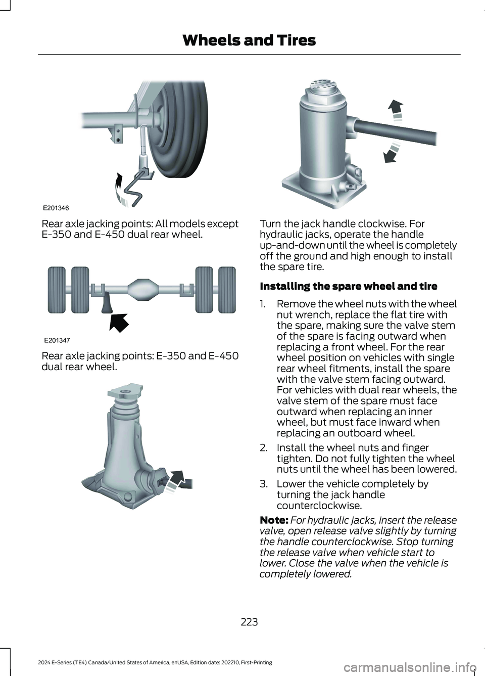
Rear axle jacking points: All models exceptE-350 and E-450 dual rear wheel.
Rear axle jacking points: E-350 and E-450dual rear wheel.
Turn the jack handle clockwise. Forhydraulic jacks, operate the handleup-and-down until the wheel is completelyoff the ground and high enough to installthe spare tire.
Installing the spare wheel and tire
1.Remove the wheel nuts with the wheelnut wrench, replace the flat tire withthe spare, making sure the valve stemof the spare is facing outward whenreplacing a front wheel. For the rearwheel position on vehicles with singlerear wheel fitments, install the sparewith the valve stem facing outward.For vehicles with dual rear wheels, thevalve stem of the spare must faceoutward when replacing an innerwheel, but must face inward whenreplacing an outboard wheel.
2.Install the wheel nuts and fingertighten. Do not fully tighten the wheelnuts until the wheel has been lowered.
3.Lower the vehicle completely byturning the jack handlecounterclockwise.
Note:For hydraulic jacks, insert the releasevalve, open release valve slightly by turningthe handle counterclockwise. Stop turningthe release valve when vehicle start tolower. Close the valve when the vehicle iscompletely lowered.
223
2024 E-Series (TE4) Canada/United States of America, enUSA, Edition date: 202210, First-PrintingWheels and TiresE201346 E201347 E162811 E162819
Page 242 of 303
CONNECTED VEHICLE
REQUIREMENTS
Connected service and related featurefunctionality requires a compatible vehiclenetwork.
Some remote features require additionalservice activation. Log in to your Fordaccount for details. Some restrictions, thirdparty terms and message or data ratesmay apply.
CONNECTED VEHICLE
LIMITATIONS
Evolving technology, cellular networks, orregulations could affect functionality andavailability, or continued provision of somefeatures. These changes could even stopsome features from functioning.
CONNECTING THE VEHICLE TO
A MOBILE NETWORK
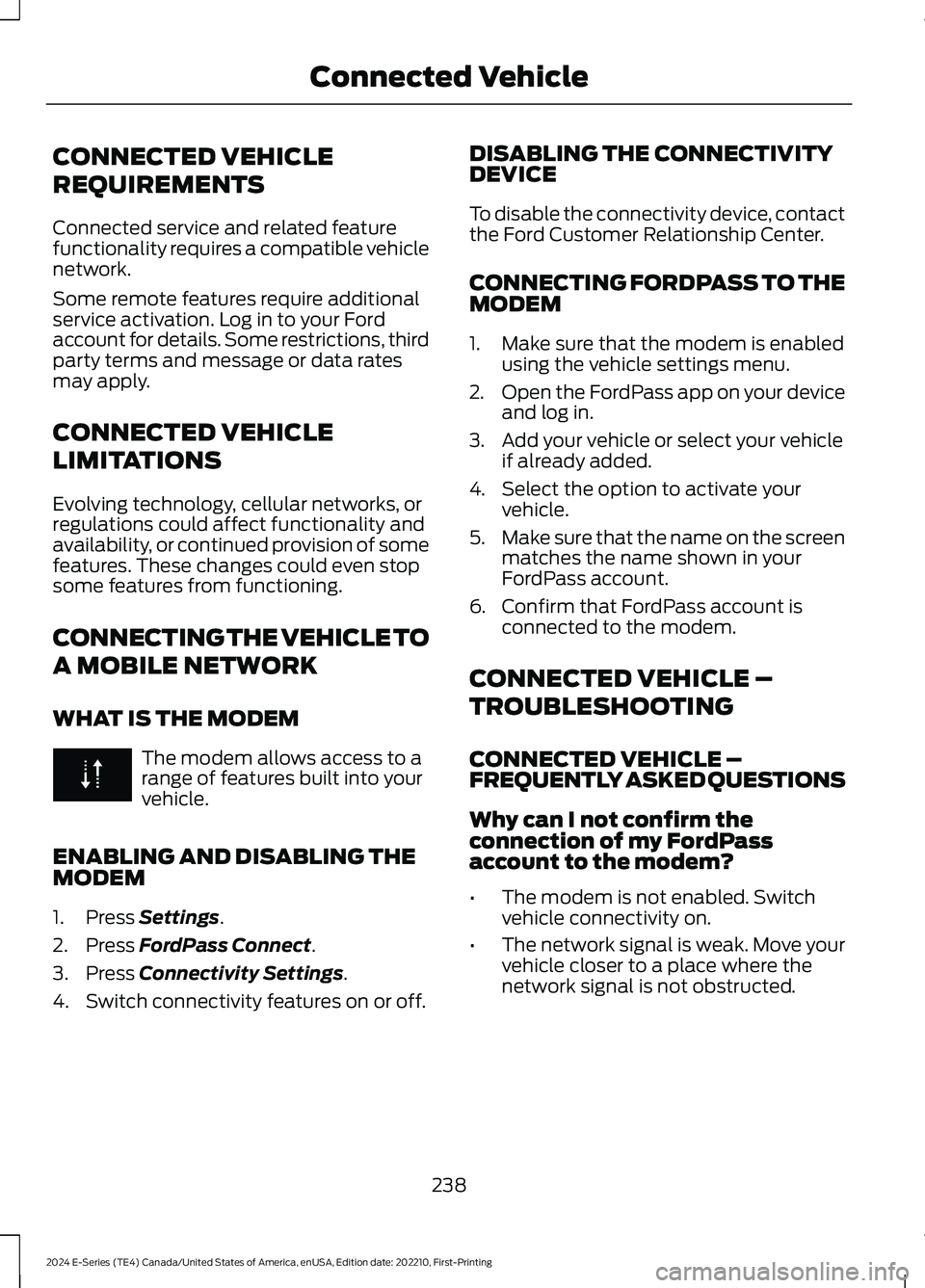
WHAT IS THE MODEM
The modem allows access to arange of features built into yourvehicle.
ENABLING AND DISABLING THEMODEM
1.Press Settings.
2.Press FordPass Connect.
3.Press Connectivity Settings.
4.Switch connectivity features on or off.
DISABLING THE CONNECTIVITYDEVICE
To disable the connectivity device, contactthe Ford Customer Relationship Center.
CONNECTING FORDPASS TO THEMODEM
1.Make sure that the modem is enabledusing the vehicle settings menu.
2.Open the FordPass app on your deviceand log in.
3.Add your vehicle or select your vehicleif already added.
4.Select the option to activate yourvehicle.
5.Make sure that the name on the screenmatches the name shown in yourFordPass account.
6.Confirm that FordPass account isconnected to the modem.
CONNECTED VEHICLE –
TROUBLESHOOTING
CONNECTED VEHICLE –FREQUENTLY ASKED QUESTIONS
Why can I not confirm theconnection of my FordPassaccount to the modem?
•The modem is not enabled. Switchvehicle connectivity on.
•The network signal is weak. Move yourvehicle closer to a place where thenetwork signal is not obstructed.
238
2024 E-Series (TE4) Canada/United States of America, enUSA, Edition date: 202210, First-PrintingConnected Vehicle
Page 273 of 303
CALIFORNIA EMISSION CONTROLWARRANTY STATEMENT
YOUR WARRANTY RIGHTS ANDOBLIGATIONS
The California Air Resources Board andFord Motor Company are pleased toexplain the emission control systemwarranty on your (year) vehicle. InCalifornia, new motor vehicles must bedesignated, built and equipped to meetthe State's stringent anti-smog standards.Ford Motor Company must warrant theemission control system on your vehiclefor the periods of time listed belowprovided there has been no abuse, neglector improper maintenance of your vehicle.
Your emission control system may includeparts such as the carburetor orfuel-injection system, the ignition system,catalytic converter and engine computer.Also included may be hoses, belts,connectors and other emission-relatedassemblies. Where a warrantable conditionexists, Ford Motor Company will repair yourvehicle at no cost to you includingdiagnosis, parts and labor.
MANUFACTURER'S WARRANTYCOVERAGE:
(For 1990 and subsequent modelpassenger cars, light-duty trucks, andmedium-duty vehicles.)
- For 3 years or 50,000 miles (whicheveroccurs first);
1) If your vehicle fails a Smog Checkinspection, all necessary repairs andadjustments will be made by Ford MotorCompany to ensure that your emissioncontrol system PERFORMANCEWARRANTY.
2) If any emission-related part on yourvehicle is defective, the part will berepaired or replaced by Ford MotorCompany. This is your short-term emissioncontrol system DEFECTS WARRANTY.
- For 7 years or 70,000 miles (whicheveroccurs first);
1) If an emission-related part listed in thiswarranty booklet specially noted withcoverage for 7 years or 70,000 miles isdefective, the part will be repaired orreplaced by Ford Motor Company. This isyour long-term emission control systemDEFECTS WARRANTY.
OWNER'S WARRANTYRESPONSIBILITIES:
- As the vehicle owner, you are responsiblefor the performance of the requiredmaintenance listed in your owner'smanual. Ford Motor Companyrecommends that you retain all receiptscovering maintenance on your vehicle, butFord Motor Company cannot denywarranty solely for the lack of receipts orfor your failure to ensure the performanceof all scheduled maintenance.
- You are responsible for presenting yourvehicle to a Ford or Lincoln dealer as soonas a problem exists. The warranty repairsshould be completed in a reasonableamount of time, not to exceed 30 days.
- As the vehicle owner, you should also beaware that Ford Motor Company may denyyou warranty coverage if your vehicle or apart has failed due to abuse, neglect,improper maintenance or unapprovedmodifications.
If you have any questions regarding yourwarranty rights and responsibilities, youshould contact Ford Customer Service at1-800-392-3673 or the California AirResource Board at 9528 Telstar Avenue,El Monte, CA 91731.
269
2024 E-Series (TE4) Canada/United States of America, enUSA, Edition date: 202210, First-PrintingCustomer Information
Page 298 of 303
Vehicle with SYNC only
United States and Mexico
FCC ID: KMHSG1G1
IC: 1422A-SG1G1
Mexico
Model: KMHSG1P1
NOM-121-SCT1-2009
The operation of this equipment is subjectto the following two conditions: (1) Thisequipment or device may not causeharmful interference, and (2) thisequipment or device must accept anyinterference, including interference thatmay cause undesired operation.
Vehicle with SYNC withTouchscreen/My Touch
FCC ID: KMHSYNCG2
IC: 1422A-SYNCG2
This device complies with Part 15 of theFCC Rules and with RSS-210 of IndustryCanada. Operation is subject to thefollowing two conditions: (1) This devicemay not cause harmful interference, and(2) this device must accept anyinterference received, includinginterference that may cause undesiredoperation.
WARNING: Changes ormodifications not expressively approvedby the party responsible for compliancecould void the user's authority to operatethe equipment. The term "IC:" before theradio certification number only signifiesthat Industry Canada technicalspecifications were met.
The antenna used for this transmitter mustnot be co-located or operating inconjunction with any other antenna ortransmitter.
294
2024 E-Series (TE4) Canada/United States of America, enUSA, Edition date: 202210, First-PrintingAppendices
Page 300 of 303
Connecting the Vehicle to a MobileNetwork............................................................238Connected Vehicle Data...............................16Connected Vehicle Limitations..............238Connected Vehicle Requirements........238Connected Vehicle –Troubleshooting........................................238Connected Vehicle – Frequently AskedQuestions........................................................238Connecting a Bluetooth® Device..........242Connecting the Vehicle to a MobileNetwork........................................................238Connecting FordPass to the Modem.........238Disabling the Connectivity Device...............238Enabling and Disabling the Modem...........238What Is the Modem..........................................238Coolant CheckSee: Engine Coolant Check............................165Cooling System Capacity andSpecification..............................................230Crash and Breakdown Information........142Automatic Crash Shutoff.................................143Crash Sensors and Airbag Indicator.......40Cruise Control................................................106Cruise Control Indicators...........................107Cruise Control - Vehicles With: AdaptiveCruise Control...............................................48Cruise Control - Vehicles With: CruiseControl............................................................48Customer Assistance..................................144Customer Information...............................258Radio Frequency CertificationLabels................................................................258
D
Data Privacy......................................................14Daytime Running Lamps - Vehicles With:Configurable Daytime RunningLamps..............................................................52Daytime Running Lamps - Vehicles With:Daytime Running Lamps (DRL)............53Direction Indicators.......................................53Doors and Locks.............................................45Driver Alert........................................................114Driver and Passenger Airbags...................36Driving Aids......................................................114Driving Hints...................................................136
Driving Through Water................................137DRLSee: Daytime Running Lamps - Vehicles With:Configurable Daytime Running Lamps....52See: Daytime Running Lamps - Vehicles With:Daytime Running Lamps (DRL)................53
E
Economical Driving......................................136Electromagnetic Compatibility..............270Emergency Call System Data.....................16Emission Law....................................................91End User License Agreement..................273Engine Block Heater......................................83Engine Coolant Check................................165Engine Emission Control..............................91Engine ImmobilizerSee: Passive Anti-Theft System.....................47Engine Oil Capacity andSpecification...............................................229Engine Oil Check...........................................163Engine Oil Dipstick.......................................163Engine Specifications................................226Environment......................................................17Essential Towing Checks...........................129Event Data.........................................................15Exterior Mirrors................................................56
F
Fastening the Seatbelts................................31Flat TireSee: Changing a Road Wheel........................218Floor Mats........................................................137Ford Credit...........................................................7Ford Protect...................................................247Fuel and Refueling.........................................85Fuel Consumption.........................................89Fuel Filter.........................................................178Fuel Quality - E85..........................................85Fuel Quality - Gasoline.................................87Fuel Tank Capacity.......................................231Fuses.................................................................150Fuse Specification Chart...........................150
296
2024 E-Series (TE4) Canada/United States of America, enUSA, Edition date: 202210, First-PrintingIndex