relay FORD E SERIES 2024 Owners Manual
[x] Cancel search | Manufacturer: FORD, Model Year: 2024, Model line: E SERIES, Model: FORD E SERIES 2024Pages: 303, PDF Size: 6.95 MB
Page 131 of 303
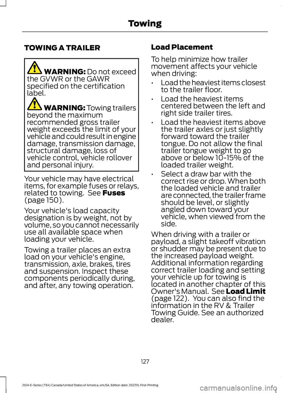
TOWING A TRAILER
WARNING: Do not exceedthe GVWR or the GAWRspecified on the certificationlabel.
WARNING: Towing trailersbeyond the maximumrecommended gross trailerweight exceeds the limit of yourvehicle and could result in enginedamage, transmission damage,structural damage, loss ofvehicle control, vehicle rolloverand personal injury.
Your vehicle may have electricalitems, for example fuses or relays,related to towing. See Fuses(page 150).
Your vehicle's load capacitydesignation is by weight, not byvolume, so you cannot necessarilyuse all available space whenloading your vehicle.
Towing a trailer places an extraload on your vehicle's engine,transmission, axle, brakes, tiresand suspension. Inspect thesecomponents periodically during,and after, any towing operation.
Load Placement
To help minimize how trailermovement affects your vehiclewhen driving:
•Load the heaviest items closestto the trailer floor.
•Load the heaviest itemscentered between the left andright side trailer tires.
•Load the heaviest items abovethe trailer axles or just slightlyforward toward the trailertongue. Do not allow the finaltrailer tongue weight to goabove or below 10-15% of theloaded trailer weight.
•Select a draw bar with thecorrect rise or drop. When boththe loaded vehicle and trailerare connected, the trailer frameshould be level, or slightlyangled down toward yourvehicle, when viewed from theside.
When driving with a trailer orpayload, a slight takeoff vibrationor shudder may be present due tothe increased payload weight.Additional information regardingcorrect trailer loading and settingyour vehicle up for towing islocated in another chapter of thisOwner's Manual. See Load Limit(page 122). You can also find theinformation in the RV & TrailerTowing Guide. See an authorizeddealer.
127
2024 E-Series (TE4) Canada/United States of America, enUSA, Edition date: 202210, First-PrintingTowing
Page 155 of 303
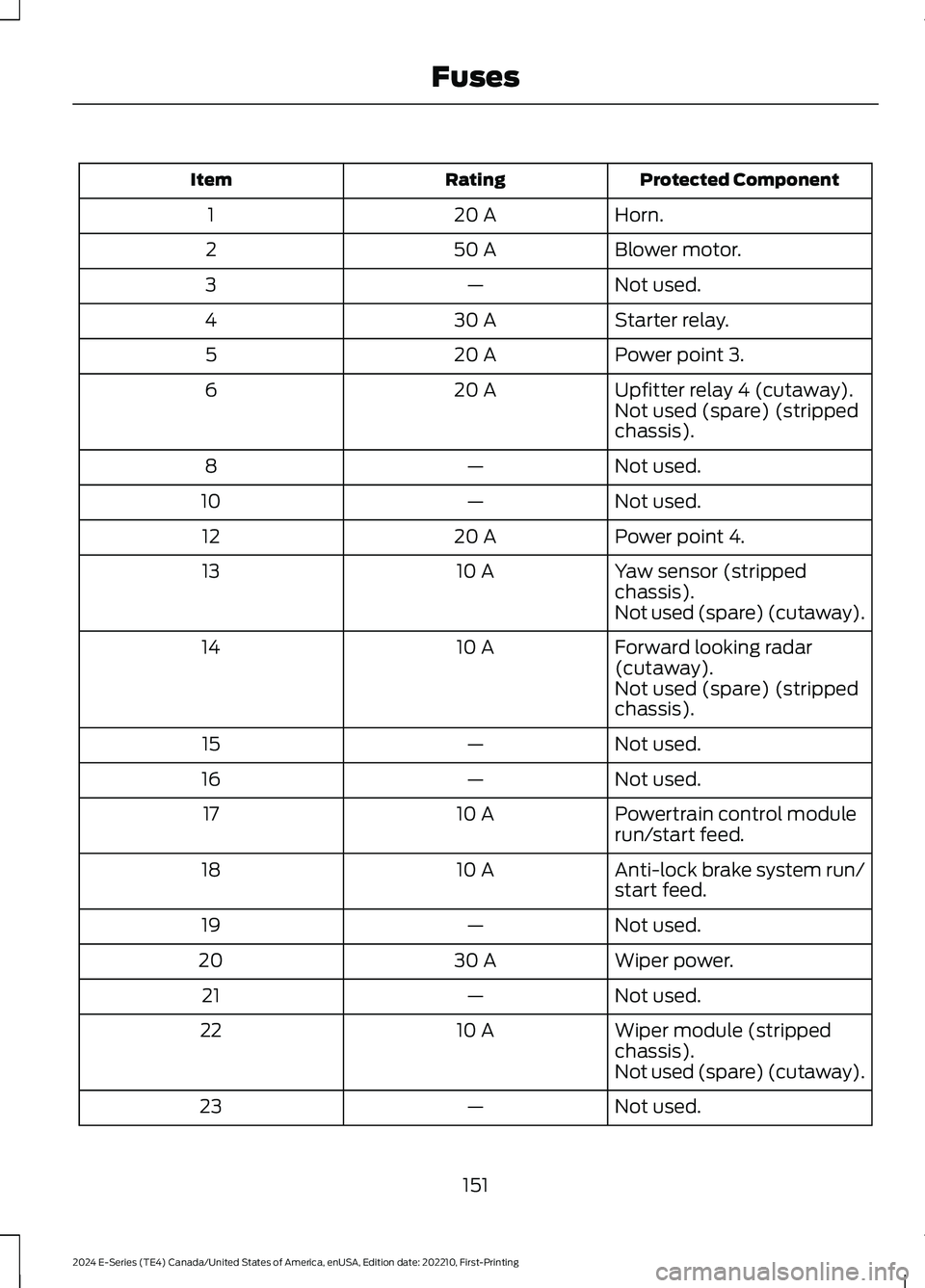
Protected ComponentRatingItem
Horn.20 A1
Blower motor.50 A2
Not used.—3
Starter relay.30 A4
Power point 3.20 A5
Upfitter relay 4 (cutaway).20 A6Not used (spare) (strippedchassis).
Not used.—8
Not used.—10
Power point 4.20 A12
Yaw sensor (strippedchassis).10 A13
Not used (spare) (cutaway).
Forward looking radar(cutaway).10 A14
Not used (spare) (strippedchassis).
Not used.—15
Not used.—16
Powertrain control modulerun/start feed.10 A17
Anti-lock brake system run/start feed.10 A18
Not used.—19
Wiper power.30 A20
Not used.—21
Wiper module (strippedchassis).10 A22
Not used (spare) (cutaway).
Not used.—23
151
2024 E-Series (TE4) Canada/United States of America, enUSA, Edition date: 202210, First-PrintingFuses
Page 156 of 303
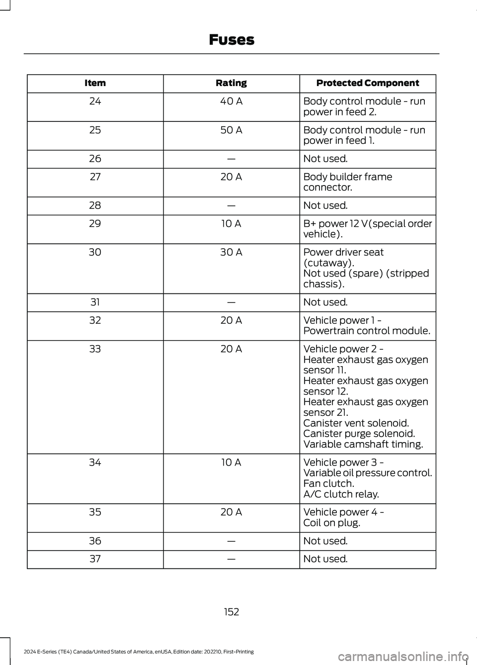
Protected ComponentRatingItem
Body control module - runpower in feed 2.40 A24
Body control module - runpower in feed 1.50 A25
Not used.—26
Body builder frameconnector.20 A27
Not used.—28
B+ power 12 V(special ordervehicle).10 A29
Power driver seat(cutaway).30 A30
Not used (spare) (strippedchassis).
Not used.—31
Vehicle power 1 -20 A32Powertrain control module.
Vehicle power 2 -20 A33Heater exhaust gas oxygensensor 11.Heater exhaust gas oxygensensor 12.Heater exhaust gas oxygensensor 21.Canister vent solenoid.Canister purge solenoid.Variable camshaft timing.
Vehicle power 3 -10 A34Variable oil pressure control.Fan clutch.A/C clutch relay.
Vehicle power 4 -20 A35Coil on plug.
Not used.—36
Not used.—37
152
2024 E-Series (TE4) Canada/United States of America, enUSA, Edition date: 202210, First-PrintingFuses
Page 157 of 303
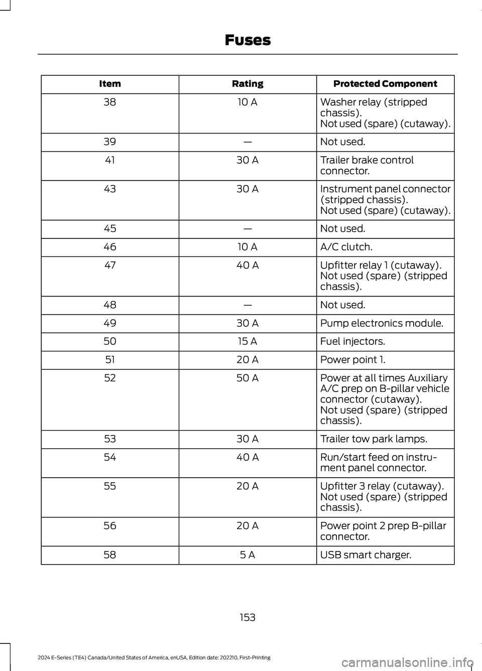
Protected ComponentRatingItem
Washer relay (strippedchassis).10 A38
Not used (spare) (cutaway).
Not used.—39
Trailer brake controlconnector.30 A41
Instrument panel connector(stripped chassis).30 A43
Not used (spare) (cutaway).
Not used.—45
A/C clutch.10 A46
Upfitter relay 1 (cutaway).40 A47Not used (spare) (strippedchassis).
Not used.—48
Pump electronics module.30 A49
Fuel injectors.15 A50
Power point 1.20 A51
Power at all times AuxiliaryA/C prep on B-pillar vehicleconnector (cutaway).
50 A52
Not used (spare) (strippedchassis).
Trailer tow park lamps.30 A53
Run/start feed on instru-ment panel connector.40 A54
Upfitter 3 relay (cutaway).20 A55Not used (spare) (strippedchassis).
Power point 2 prep B-pillarconnector.20 A56
USB smart charger.5 A58
153
2024 E-Series (TE4) Canada/United States of America, enUSA, Edition date: 202210, First-PrintingFuses
Page 159 of 303
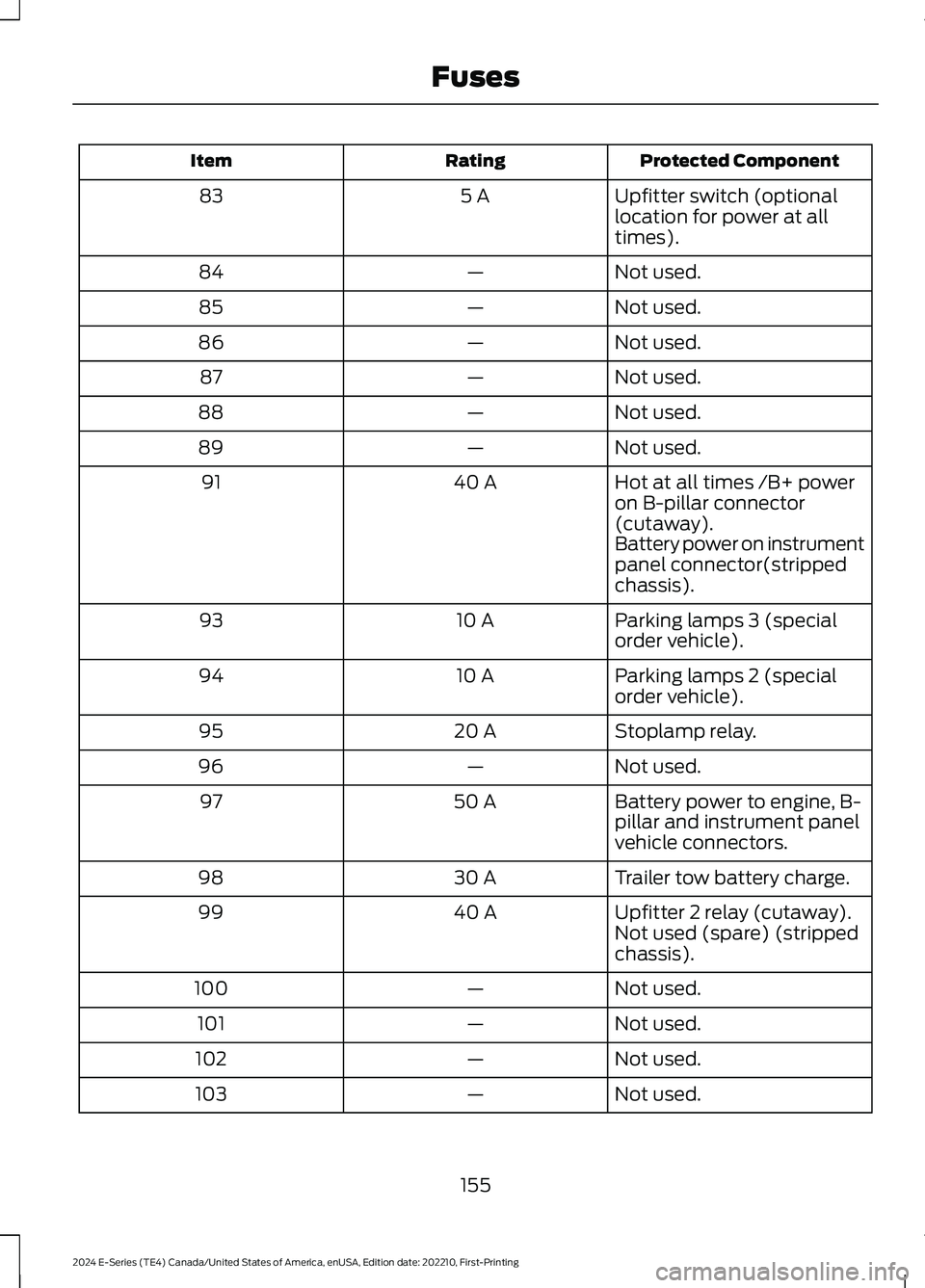
Protected ComponentRatingItem
Upfitter switch (optionallocation for power at alltimes).
5 A83
Not used.—84
Not used.—85
Not used.—86
Not used.—87
Not used.—88
Not used.—89
Hot at all times /B+ poweron B-pillar connector(cutaway).
40 A91
Battery power on instrumentpanel connector(strippedchassis).
Parking lamps 3 (specialorder vehicle).10 A93
Parking lamps 2 (specialorder vehicle).10 A94
Stoplamp relay.20 A95
Not used.—96
Battery power to engine, B-pillar and instrument panelvehicle connectors.
50 A97
Trailer tow battery charge.30 A98
Upfitter 2 relay (cutaway).40 A99Not used (spare) (strippedchassis).
Not used.—100
Not used.—101
Not used.—102
Not used.—103
155
2024 E-Series (TE4) Canada/United States of America, enUSA, Edition date: 202210, First-PrintingFuses
Page 160 of 303
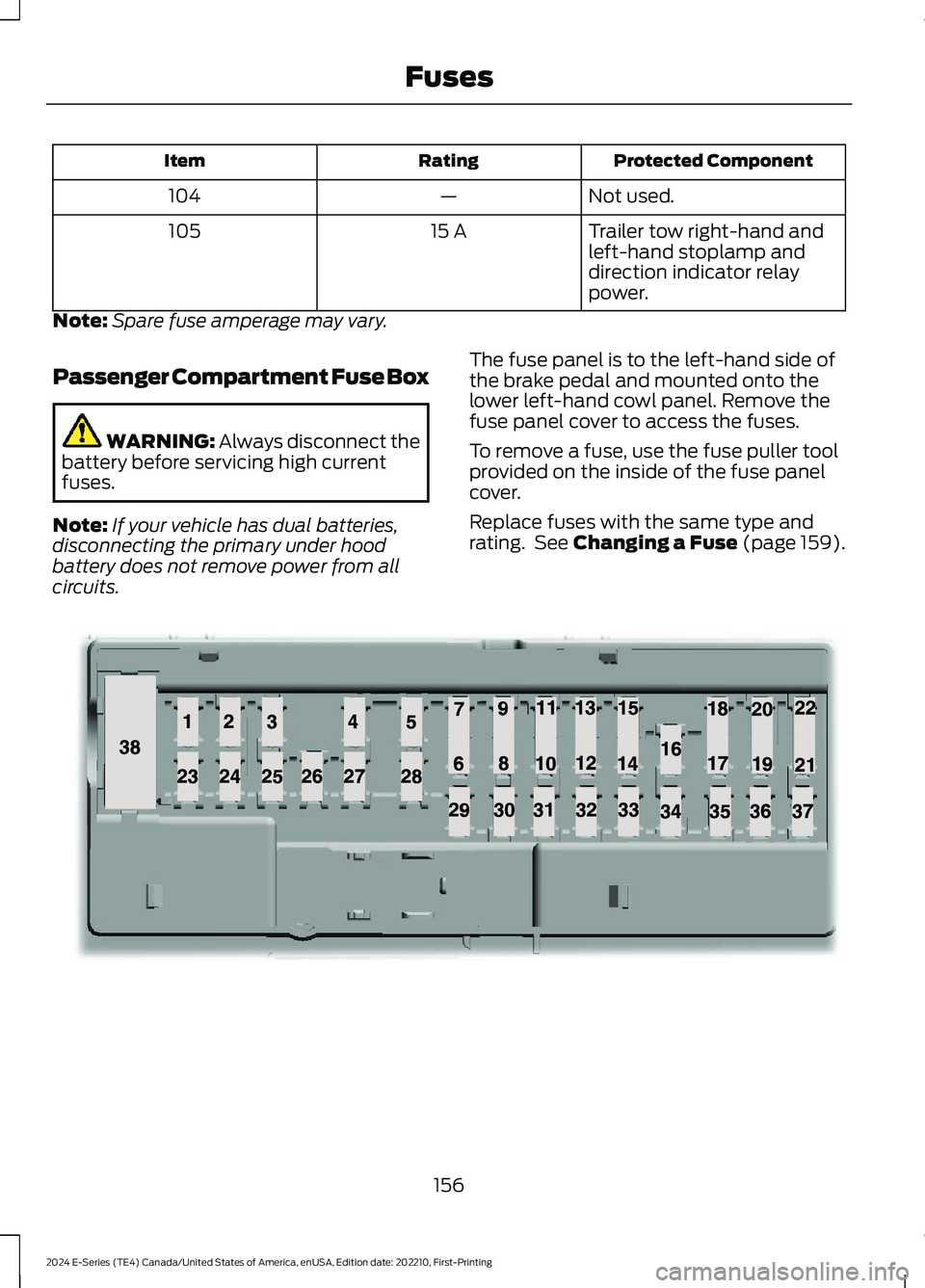
Protected ComponentRatingItem
Not used.—104
Trailer tow right-hand andleft-hand stoplamp anddirection indicator relaypower.
15 A105
Note:Spare fuse amperage may vary.
Passenger Compartment Fuse Box
WARNING: Always disconnect thebattery before servicing high currentfuses.
Note:If your vehicle has dual batteries,disconnecting the primary under hoodbattery does not remove power from allcircuits.
The fuse panel is to the left-hand side ofthe brake pedal and mounted onto thelower left-hand cowl panel. Remove thefuse panel cover to access the fuses.
To remove a fuse, use the fuse puller toolprovided on the inside of the fuse panelcover.
Replace fuses with the same type andrating. See Changing a Fuse (page 159).
156
2024 E-Series (TE4) Canada/United States of America, enUSA, Edition date: 202210, First-PrintingFusesE145984
Page 249 of 303
AUXILIARY SWITCHES (IF
EQUIPPED)
For maximum vehicle performance, keepthe following information in mind whenadding accessories or equipment to yourvehicle:
•When adding accessories, equipment,passengers and luggage to yourvehicle, do not exceed the total weightcapacity of the vehicle or of the frontor rear axle (GVWR or GAWR asindicated on the Safety ComplianceCertification label). Ask an authorizeddealer for specific weight information.
•The Federal CommunicationsCommission (FCC) and CanadianRadio TelecommunicationsCommission (CRTC) regulate the useof mobile communications systemsequipped with radio transmitters, forexample, two-way radios, telephonesand theft alarms. Any such equipmentinstalled in your vehicle should complywith Federal CommunicationsCommission (FCC) and CanadianRadio TelecommunicationsCommission (CRTC) regulations, andshould be installed by an authorizeddealer.
•An authorized dealer needs to installmobile communications systems.Improper installation may harm theoperation of your vehicle, particularlyif the manufacturer did not design themobile communication systemspecifically for automotive use.
•If you or an authorized Ford dealer addany non-Ford electrical or electronicaccessories or components to yourvehicle, you may adversely affectbattery performance and durability. Inaddition, you may also adversely affectthe performance of other electricalsystems in the vehicle.
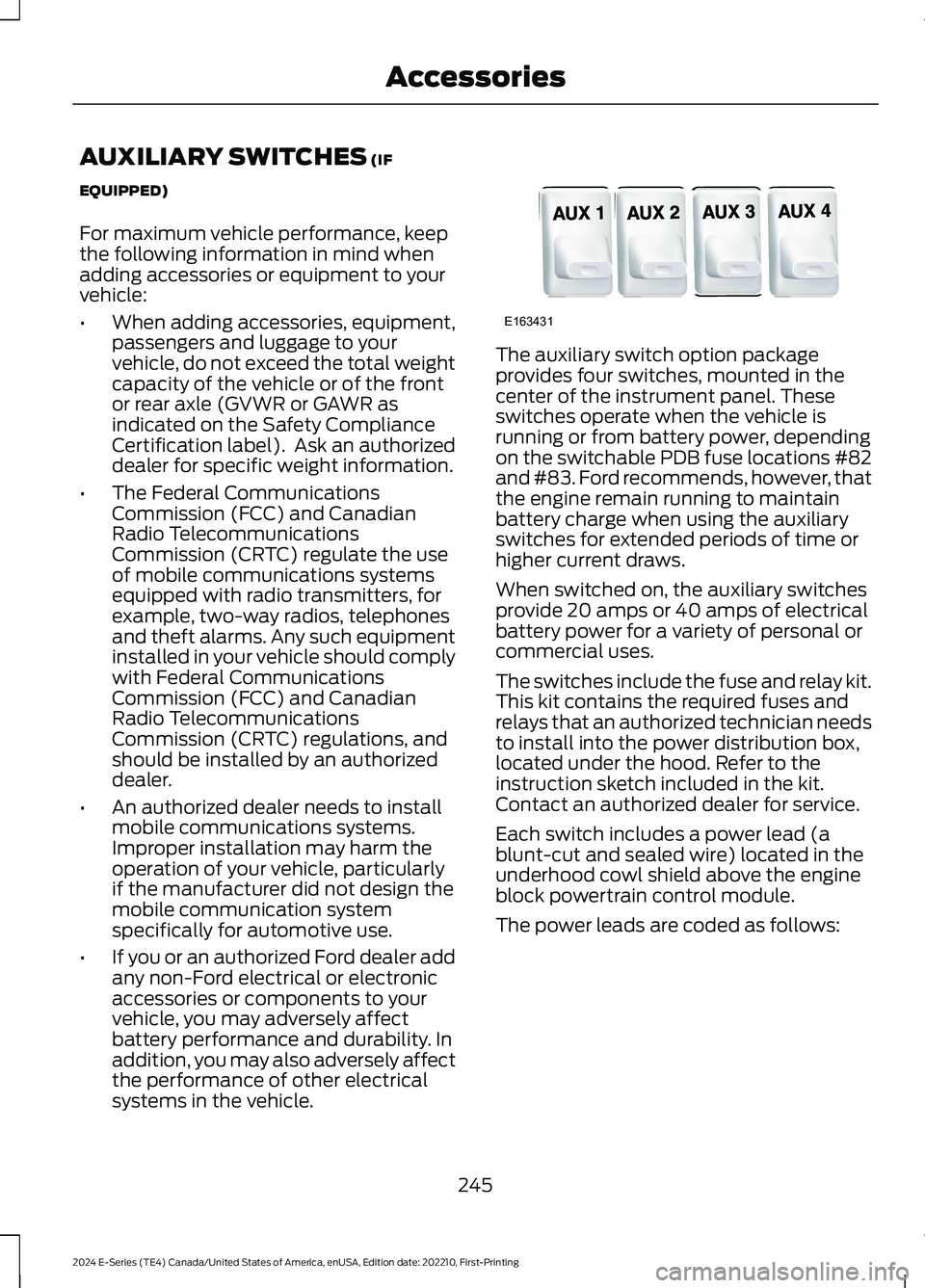
The auxiliary switch option packageprovides four switches, mounted in thecenter of the instrument panel. Theseswitches operate when the vehicle isrunning or from battery power, dependingon the switchable PDB fuse locations #82and #83. Ford recommends, however, thatthe engine remain running to maintainbattery charge when using the auxiliaryswitches for extended periods of time orhigher current draws.
When switched on, the auxiliary switchesprovide 20 amps or 40 amps of electricalbattery power for a variety of personal orcommercial uses.
The switches include the fuse and relay kit.This kit contains the required fuses andrelays that an authorized technician needsto install into the power distribution box,located under the hood. Refer to theinstruction sketch included in the kit.Contact an authorized dealer for service.
Each switch includes a power lead (ablunt-cut and sealed wire) located in theunderhood cowl shield above the engineblock powertrain control module.
The power leads are coded as follows:
245
2024 E-Series (TE4) Canada/United States of America, enUSA, Edition date: 202210, First-PrintingAccessoriesE163431
Page 250 of 303
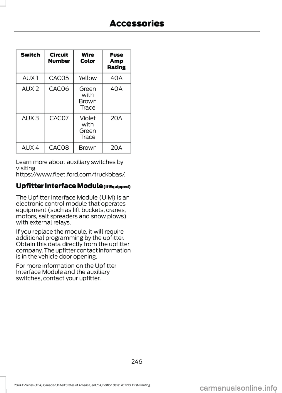
FuseAmpRating
WireColorCircuitNumberSwitch
40AYellowCAC05AUX 1
40AGreenwithBrownTrace
CAC06AUX 2
20AVioletwithGreenTrace
CAC07AUX 3
20ABrownCAC08AUX 4
Learn more about auxiliary switches byvisitinghttps://www.fleet.ford.com/truckbbas/.
Upfitter Interface Module (If Equipped)
The Upfitter Interface Module (UIM) is anelectronic control module that operatesequipment (such as lift buckets, cranes,motors, salt spreaders and snow plows)with external relays.
If you replace the module, it will requireadditional programming by the upfitter.Obtain this data directly from the upfittercompany. The upfitter contact informationis in the vehicle door opening.
For more information on the UpfitterInterface Module and the auxiliaryswitches, contact your upfitter.
246
2024 E-Series (TE4) Canada/United States of America, enUSA, Edition date: 202210, First-PrintingAccessories