headlamp FORD EDGE 2018 User Guide
[x] Cancel search | Manufacturer: FORD, Model Year: 2018, Model line: EDGE, Model: FORD EDGE 2018Pages: 557, PDF Size: 7.02 MB
Page 115 of 557
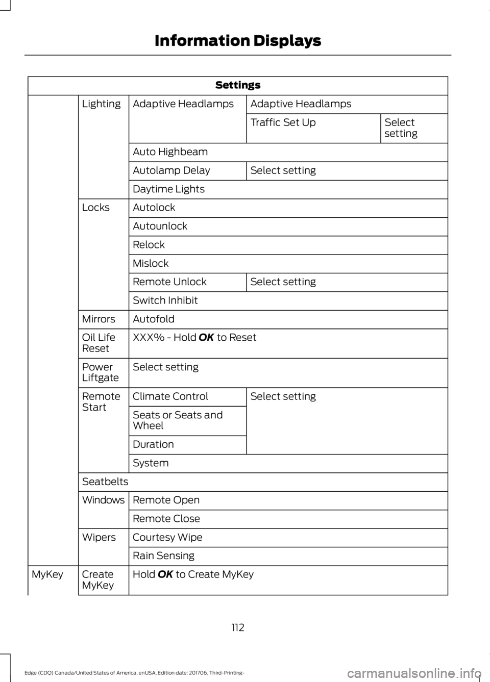
Settings
Adaptive Headlamps
Adaptive Headlamps
Lighting
Select
setting
Traffic Set Up
Auto Highbeam Select setting
Autolamp Delay
Daytime Lights
Autolock
Locks
Autounlock
Relock
Mislock Select setting
Remote Unlock
Switch Inhibit
Autofold
Mirrors
XXX% - Hold OK to Reset
Oil Life
Reset
Select setting
Power
Liftgate
Select setting
Climate Control
Remote
Start
Seats or Seats and
Wheel
Duration
System
Seatbelts Remote Open
Windows
Remote Close
Courtesy Wipe
Wipers
Rain Sensing
Hold
OK to Create MyKey
Create
MyKey
MyKey
112
Edge (CDQ) Canada/United States of America, enUSA, Edition date: 201706, Third-Printing- Information Displays
Page 163 of 557
Start: Starts your vehicle. The engine may
not start when your vehicle starts.
• Press the brake pedal, and then press
the button for any length of time. An
indicator light on the button illuminates
when the ignition is on and when your
vehicle starts.
STARTING A GASOLINE
ENGINE
When you start the engine, the idle speed
increases. This helps to warm up the
engine. If the engine idle speed does not
slow down automatically, have your
vehicle checked by an authorized dealer.
Note: You can crank the engine for a total
of 60 seconds without the engine starting
before the starting system temporarily
disables. The 60 seconds does not have to
be all at once. For example, if you crank the
engine three times for 20 seconds each
time, without the engine starting, you
reached the 60-second time limit. A
message appears in the information display
alerting you that you exceeded the cranking
time. You cannot attempt to start the
engine for at least 15 minutes. After 15
minutes, you are limited to a 15-second
engine cranking time. You need to wait 60
minutes before you can crank the engine for
60 seconds again.
Before starting the engine check the
following:
• Make sure all occupants have fastened
their seatbelts.
• Make sure the headlamps and
electrical accessories are off.
• Make sure the parking brake is on.
• Make sure the transmission is in park
(P) or neutral.
Note: Do not touch the accelerator pedal. Note:
A valid passive key must be located
inside your vehicle to switch the power on
and start your vehicle.
1. Press the brake pedal.
2. Briefly press the push button ignition switch.
The system does not function if:
• The passive key frequencies are
jammed.
• The key battery has no charge.
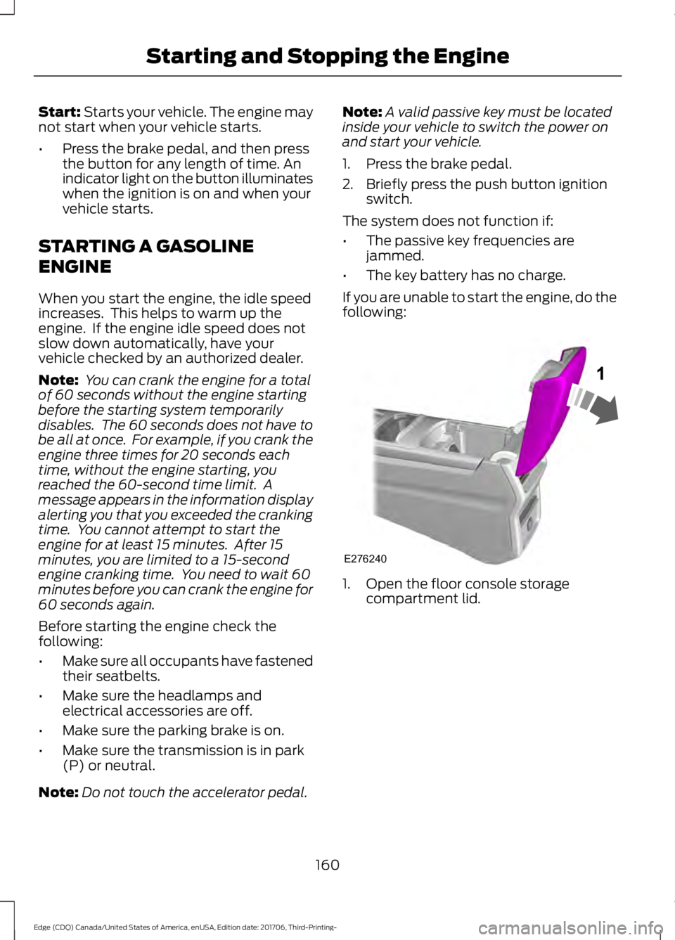
If you are unable to start the engine, do the
following: 1. Open the floor console storage
compartment lid.
160
Edge (CDQ) Canada/United States of America, enUSA, Edition date: 201706, Third-Printing- Starting and Stopping the EngineE276240
Page 223 of 557
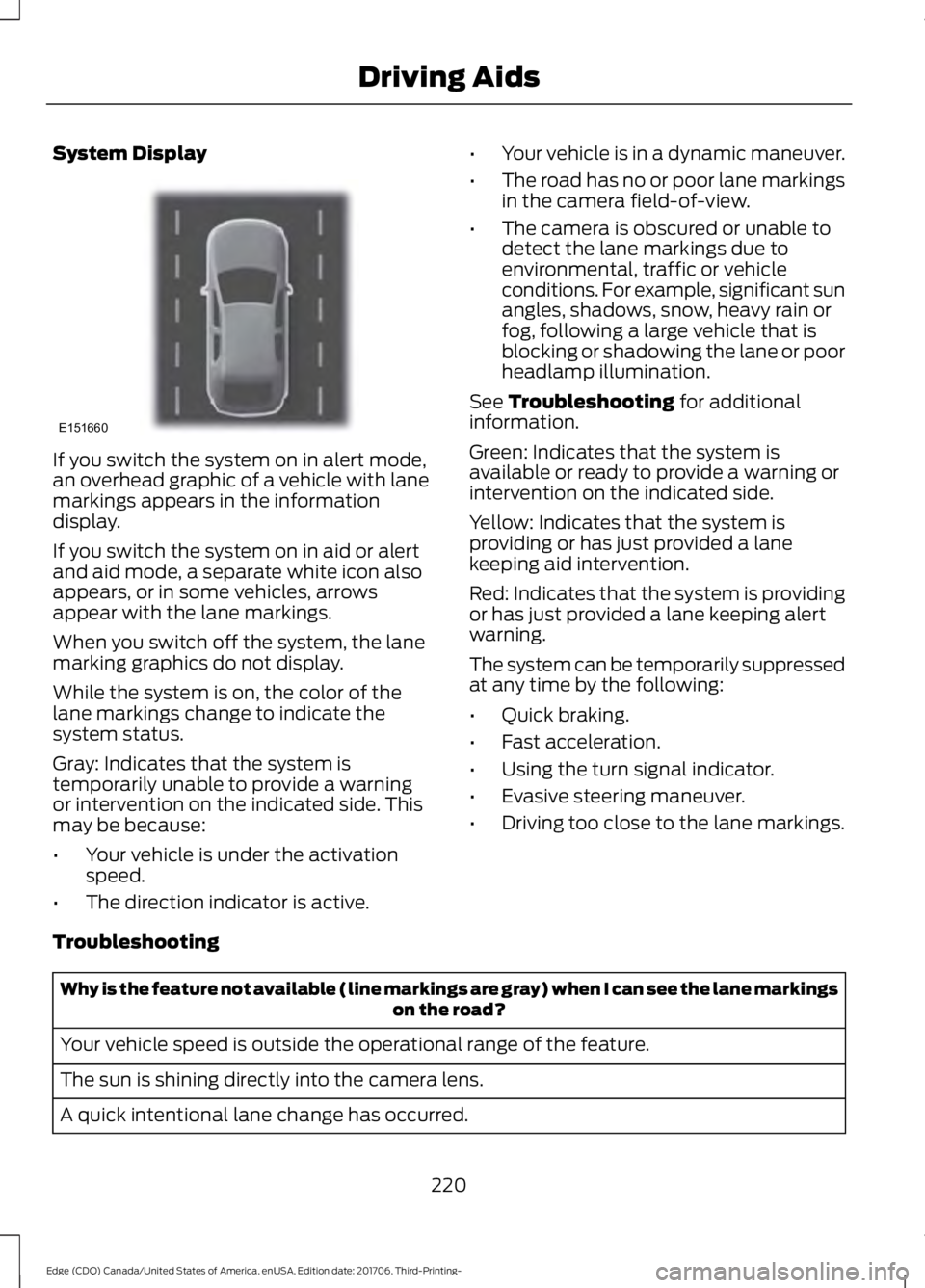
System Display
If you switch the system on in alert mode,
an overhead graphic of a vehicle with lane
markings appears in the information
display.
If you switch the system on in aid or alert
and aid mode, a separate white icon also
appears, or in some vehicles, arrows
appear with the lane markings.
When you switch off the system, the lane
marking graphics do not display.
While the system is on, the color of the
lane markings change to indicate the
system status.
Gray: Indicates that the system is
temporarily unable to provide a warning
or intervention on the indicated side. This
may be because:
•
Your vehicle is under the activation
speed.
• The direction indicator is active. •
Your vehicle is in a dynamic maneuver.
• The road has no or poor lane markings
in the camera field-of-view.
• The camera is obscured or unable to
detect the lane markings due to
environmental, traffic or vehicle
conditions. For example, significant sun
angles, shadows, snow, heavy rain or
fog, following a large vehicle that is
blocking or shadowing the lane or poor
headlamp illumination.
See Troubleshooting for additional
information.
Green: Indicates that the system is
available or ready to provide a warning or
intervention on the indicated side.
Yellow: Indicates that the system is
providing or has just provided a lane
keeping aid intervention.
Red: Indicates that the system is providing
or has just provided a lane keeping alert
warning.
The system can be temporarily suppressed
at any time by the following:
• Quick braking.
• Fast acceleration.
• Using the turn signal indicator.
• Evasive steering maneuver.
• Driving too close to the lane markings.
Troubleshooting Why is the feature not available (line markings are gray) when I can see the lane markings
on the road?
Your vehicle speed is outside the operational range of the feature.
The sun is shining directly into the camera lens.
A quick intentional lane change has occurred.
220
Edge (CDQ) Canada/United States of America, enUSA, Edition date: 201706, Third-Printing- Driving AidsE151660
Page 232 of 557
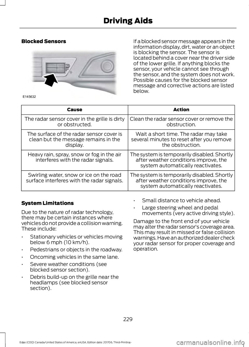
Blocked Sensors If a blocked sensor message appears in the
information display, dirt, water or an object
is blocking the sensor. The sensor is
located behind a cover near the driver side
of the lower grille. If anything blocks the
sensor, your vehicle cannot see through
the sensor, and the system does not work.
Possible causes for the blocked sensor
message and corrective actions are listed
below.
Action
Cause
Clean the radar sensor cover or remove theobstruction.
The radar sensor cover in the grille is dirty
or obstructed.
Wait a short time. The radar may take
several minutes to reset after you remove the obstruction.
The surface of the radar sensor cover is
clean but the message remains in the display.
The system is temporarily disabled. Shortlyafter weather conditions improve, thesystem automatically reactivates.
Heavy rain, spray, snow or fog in the air
interferes with the radar signals.
The system is temporarily disabled. Shortlyafter weather conditions improve, thesystem automatically reactivates.
Swirling water, snow or ice on the road
surface interferes with the radar signals.
System Limitations
Due to the nature of radar technology,
there may be certain instances where
vehicles do not provide a collision warning.
These include:
• Stationary vehicles or vehicles moving
below 6 mph (10 km/h).
• Pedestrians or objects in the roadway.
• Oncoming vehicles in the same lane.
• Severe weather conditions (see
blocked sensor section).
• Debris build-up on the grille near the
headlamps (see blocked sensor
section). •
Small distance to vehicle ahead.
• Large steering wheel and pedal
movements (very active driving style).
Damage to the front end of your vehicle
may alter the radar sensor's coverage area.
This may result in missed or false collision
warnings. Have an authorized dealer check
your radar sensor for proper coverage and
operation.
229
Edge (CDQ) Canada/United States of America, enUSA, Edition date: 201706, Third-Printing- Driving AidsE145632
Page 254 of 557
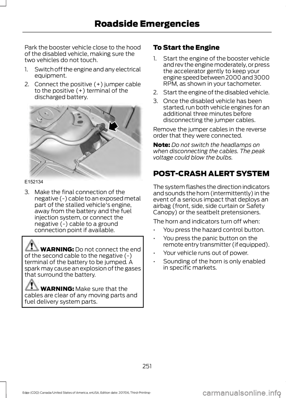
Park the booster vehicle close to the hood
of the disabled vehicle, making sure the
two vehicles do not touch.
1.
Switch off the engine and any electrical
equipment.
2. Connect the positive (+) jumper cable
to the positive (+) terminal of the
discharged battery. 3. Make the final connection of the
negative (-) cable to an exposed metal
part of the stalled vehicle's engine,
away from the battery and the fuel
injection system, or connect the
negative (-) cable to a ground
connection point if available. WARNING: Do not connect the end
of the second cable to the negative (-)
terminal of the battery to be jumped. A
spark may cause an explosion of the gases
that surround the battery. WARNING:
Make sure that the
cables are clear of any moving parts and
fuel delivery system parts. To Start the Engine
1.
Start the engine of the booster vehicle
and rev the engine moderately, or press
the accelerator gently to keep your
engine speed between 2000 and 3000
RPM, as shown in your tachometer.
2. Start the engine of the disabled vehicle.
3. Once the disabled vehicle has been started, run both vehicle engines for an
additional three minutes before
disconnecting the jumper cables.
Remove the jumper cables in the reverse
order that they were connected.
Note: Do not switch the headlamps on
when disconnecting the cables. The peak
voltage could blow the bulbs.
POST-CRASH ALERT SYSTEM
The system flashes the direction indicators
and sounds the horn (intermittently) in the
event of a serious impact that deploys an
airbag (front, side, side curtain or Safety
Canopy) or the seatbelt pretensioners.
The horn and indicators turn off when:
• You press the hazard control button.
• You press the panic button on the
remote entry transmitter (if equipped).
• Your vehicle runs out of power.
• Sounding of the horn is only enabled
in specific markets.
251
Edge (CDQ) Canada/United States of America, enUSA, Edition date: 201706, Third-Printing- Roadside EmergenciesE152134
Page 264 of 557
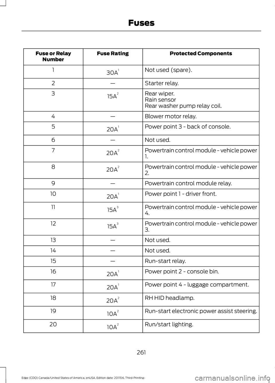
Protected Components
Fuse Rating
Fuse or Relay
Number
Not used (spare).
30A 1
1
Starter relay.
—
2
Rear wiper.
15A 2
3
Rain sensor
Rear washer pump relay coil.
Blower motor relay.
—
4
Power point 3 - back of console.
20A 1
5
Not used.
—
6
Powertrain control module - vehicle power
1.
20A 2
7
Powertrain control module - vehicle power
2.
20A 2
8
Powertrain control module relay.
—
9
Power point 1 - driver front.
20A 1
10
Powertrain control module - vehicle power
4.
15A 3
11
Powertrain control module - vehicle power
3.
15A 3
12
Not used.
—
13
Not used.
—
14
Run-start relay.
—
15
Power point 2 - console bin.
20A 1
16
Power point 4 - luggage compartment.
20A 1
17
RH HID headlamp.
20A 2
18
Run-start electronic power assist steering.
10A 2
19
Run/start lighting.
10A 2
20
261
Edge (CDQ) Canada/United States of America, enUSA, Edition date: 201706, Third-Printing- Fuses
Page 266 of 557
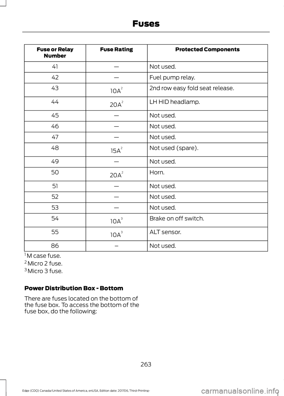
Protected Components
Fuse Rating
Fuse or Relay
Number
Not used.
—
41
Fuel pump relay.
—
42
2nd row easy fold seat release.
10A 2
43
LH HID headlamp.
20A 2
44
Not used.
—
45
Not used.
—
46
Not used.
—
47
Not used (spare).
15A 2
48
Not used.
—
49
Horn.
20A 2
50
Not used.
—
51
Not used.
—
52
Not used.
—
53
Brake on off switch.
10A 3
54
ALT sensor.
10A 3
55
Not used.
–
86
1 M case fuse.
2 Micro 2 fuse.
3 Micro 3 fuse.
Power Distribution Box - Bottom
There are fuses located on the bottom of
the fuse box. To access the bottom of the
fuse box, do the following:
263
Edge (CDQ) Canada/United States of America, enUSA, Edition date: 201706, Third-Printing- Fuses
Page 292 of 557
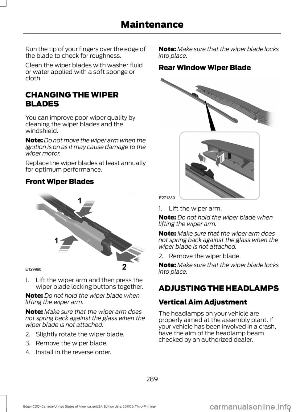
Run the tip of your fingers over the edge of
the blade to check for roughness.
Clean the wiper blades with washer fluid
or water applied with a soft sponge or
cloth.
CHANGING THE WIPER
BLADES
You can improve poor wiper quality by
cleaning the wiper blades and the
windshield.
Note:
Do not move the wiper arm when the
ignition is on as it may cause damage to the
wiper motor.
Replace the wiper blades at least annually
for optimum performance.
Front Wiper Blades 1. Lift the wiper arm and then press the
wiper blade locking buttons together.
Note: Do not hold the wiper blade when
lifting the wiper arm.
Note: Make sure that the wiper arm does
not spring back against the glass when the
wiper blade is not attached.
2. Slightly rotate the wiper blade.
3. Remove the wiper blade.
4. Install in the reverse order. Note:
Make sure that the wiper blade locks
into place.
Rear Window Wiper Blade 1. Lift the wiper arm.
Note:
Do not hold the wiper blade when
lifting the wiper arm.
Note: Make sure that the wiper arm does
not spring back against the glass when the
wiper blade is not attached.
2. Remove the wiper blade.
Note: Make sure that the wiper blade locks
into place.
ADJUSTING THE HEADLAMPS
Vertical Aim Adjustment
The headlamps on your vehicle are
properly aimed at the assembly plant. If
your vehicle has been involved in a crash,
have the aim of the headlamp beam
checked by an authorized dealer.
289
Edge (CDQ) Canada/United States of America, enUSA, Edition date: 201706, Third-Printing- MaintenanceE129990
1
1 2 E271380
Page 293 of 557
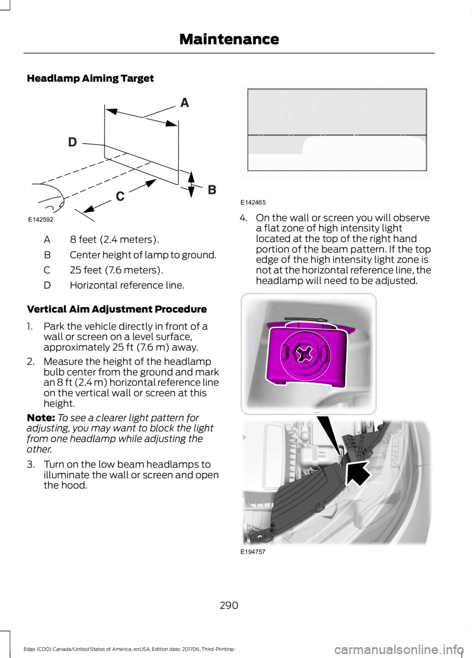
Headlamp Aiming Target
8 feet (2.4 meters).
A
Center height of lamp to ground.
B
25 feet (7.6 meters).
C
Horizontal reference line.
D
Vertical Aim Adjustment Procedure
1. Park the vehicle directly in front of a wall or screen on a level surface,
approximately 25 ft (7.6 m) away.
2. Measure the height of the headlamp bulb center from the ground and mark
an
8 ft (2.4 m) horizontal reference line
on the vertical wall or screen at this
height.
Note: To see a clearer light pattern for
adjusting, you may want to block the light
from one headlamp while adjusting the
other.
3. Turn on the low beam headlamps to illuminate the wall or screen and open
the hood. 4. On the wall or screen you will observe
a flat zone of high intensity light
located at the top of the right hand
portion of the beam pattern. If the top
edge of the high intensity light zone is
not at the horizontal reference line, the
headlamp will need to be adjusted. 290
Edge (CDQ) Canada/United States of America, enUSA, Edition date: 201706, Third-Printing- MaintenanceE142592 E142465 E194757
Page 294 of 557
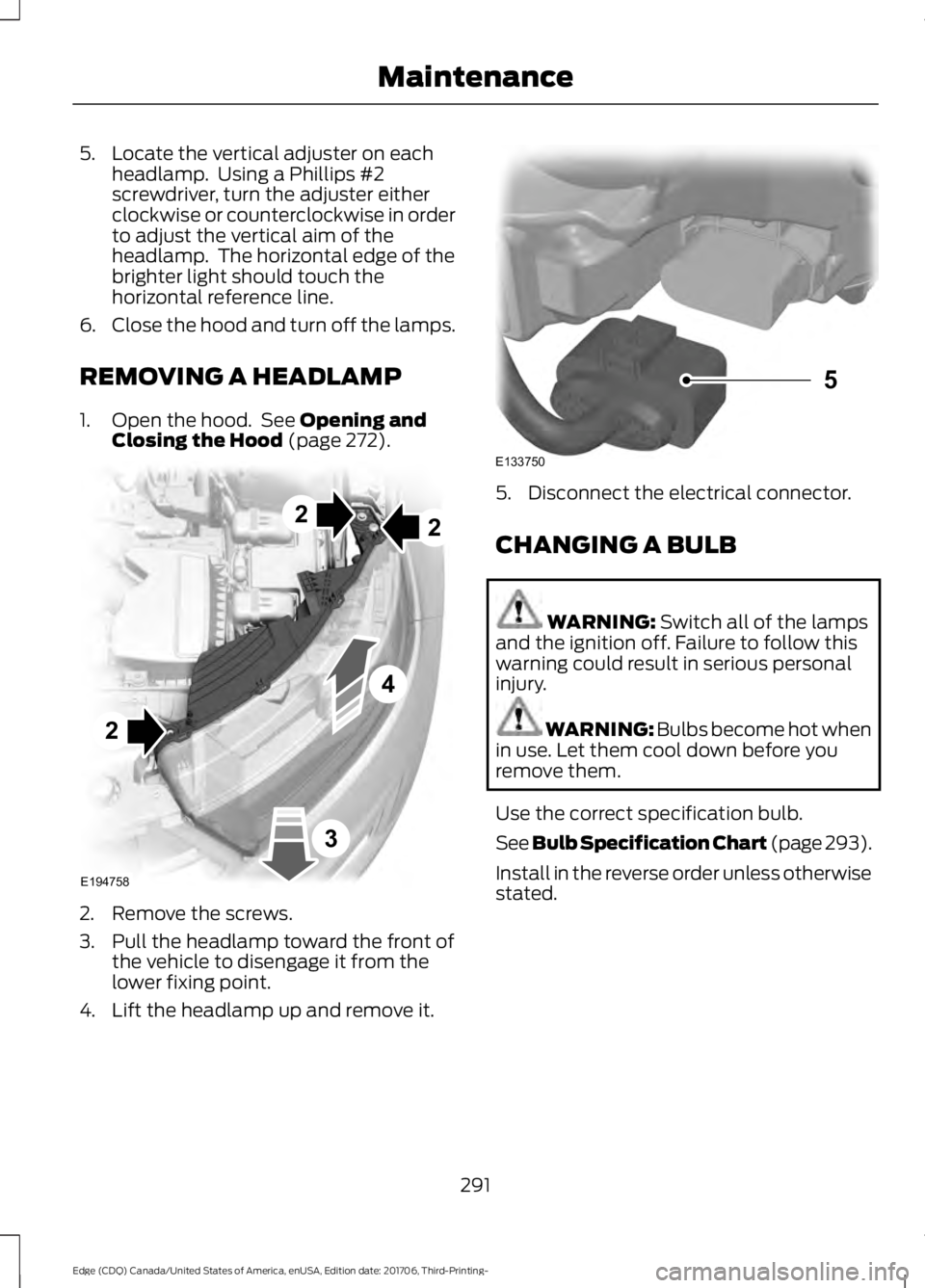
5. Locate the vertical adjuster on each
headlamp. Using a Phillips #2
screwdriver, turn the adjuster either
clockwise or counterclockwise in order
to adjust the vertical aim of the
headlamp. The horizontal edge of the
brighter light should touch the
horizontal reference line.
6. Close the hood and turn off the lamps.
REMOVING A HEADLAMP
1. Open the hood. See Opening and
Closing the Hood (page 272). 2. Remove the screws.
3. Pull the headlamp toward the front of
the vehicle to disengage it from the
lower fixing point.
4. Lift the headlamp up and remove it. 5. Disconnect the electrical connector.
CHANGING A BULB
WARNING:
Switch all of the lamps
and the ignition off. Failure to follow this
warning could result in serious personal
injury. WARNING: Bulbs become hot when
in use. Let them cool down before you
remove them.
Use the correct specification bulb.
See Bulb Specification Chart (page 293).
Install in the reverse order unless otherwise
stated.
291
Edge (CDQ) Canada/United States of America, enUSA, Edition date: 201706, Third-Printing- Maintenance2
2
E194758
2
4
3 E133750
5