FORD ESCAPE 2022 Owners Manual
Manufacturer: FORD, Model Year: 2022, Model line: ESCAPE, Model: FORD ESCAPE 2022Pages: 585, PDF Size: 6.15 MB
Page 341 of 585
The air conditioning may automatically
turn on and off during severe operating
conditions to protect the engine from
overheating. When the coolant
temperature decreases to the normal
operating temperature, the air conditioning
turns on.
If the coolant temperature gauge moves
fully into the red zone, or if the coolant
temperature warning or service engine
soon messages appear in your information
display, do the following:
1. Stop your vehicle as soon as it is safeto do so. Fully apply the parking brake,
shift into park (P) or neutral (N).
2. Leave the engine running until the coolant temperature gauge needle
returns to the normal position. If the
temperature does not drop after
several minutes, follow the remaining
steps.
3. Switch the engine off and wait for it to cool. Check the coolant level.
4. If the coolant level is at or below the minimum mark, add prediluted coolant
immediately.
5. If the coolant level is normal, restart the engine and continue.
CHANGING THE ENGINE AIR
FILTER - 1.5L ECOBOOST™/
2.0L ECOBOOST™
WARNING: To reduce the risk of
vehicle damage and personal burn
injuries, do not start your engine with the
air cleaner removed and do not remove
it while the engine is running.
When changing the air filter element, use
only parts that meet or exceed our
specifications. For EcoBoost equipped vehicles: When
servicing the air cleaner, it is important that
no foreign material enter the air induction
system. The engine and turbocharger are
susceptible to damage from even small
particles.
Change the air filter element at the proper
interval. See Scheduled Maintenance
(page 482).
Note:
Failure to use the correct air filter
element may result in severe engine
damage. The customer warranty may be
void for any damage to the engine if the
correct air filter element is not used.
E299070E299070E299E299E2992920700700707070070
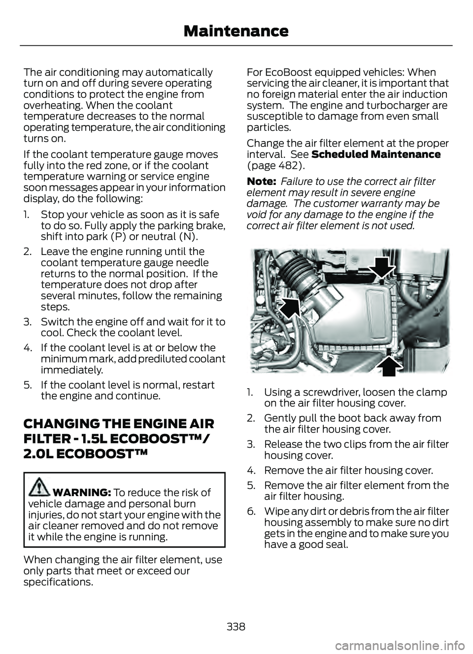
1. Using a screwdriver, loosen the clamp on the air filter housing cover.
2. Gently pull the boot back away from the air filter housing cover.
3. Release the two clips from the air filter housing cover.
4. Remove the air filter housing cover.
5. Remove the air filter element from the air filter housing.
6. Wipe any dirt or debris from the air filter housing assembly to make sure no dirt
gets in the engine and to make sure you
have a good seal.
338
Maintenance
Page 342 of 585
E299073E299073
7. Install a new air filter element. Becareful not to crimp the filter element
edges between the air filter housing
and cover. This could cause filter
damage and allow unfiltered air to
enter the engine if it is not properly
seated.
8. Install the air filter housing cover.
9. Engage the clips to secure the air filter housing cover to the air filter housing.
10. Reconnect the boot to the air filter housing cover and tighten securely.
CHANGING THE ENGINE AIR
FILTER - 2.5L, HYBRID
ELECTRIC VEHICLE (HEV)/
PLUG-IN HYBRID ELECTRIC
VEHICLE (PHEV)
WARNING: To reduce the risk of
vehicle damage and personal burn
injuries, do not start your engine with the
air cleaner removed and do not remove
it while the engine is running. When changing the air filter element, use
only parts that meet or exceed our
specifications.
Change the air filter element at the proper
interval. See Scheduled Maintenance
(page 482).
Note:
If you do not use the correct air filter
element, your vehicle warranty could be
void.
E299071E299071
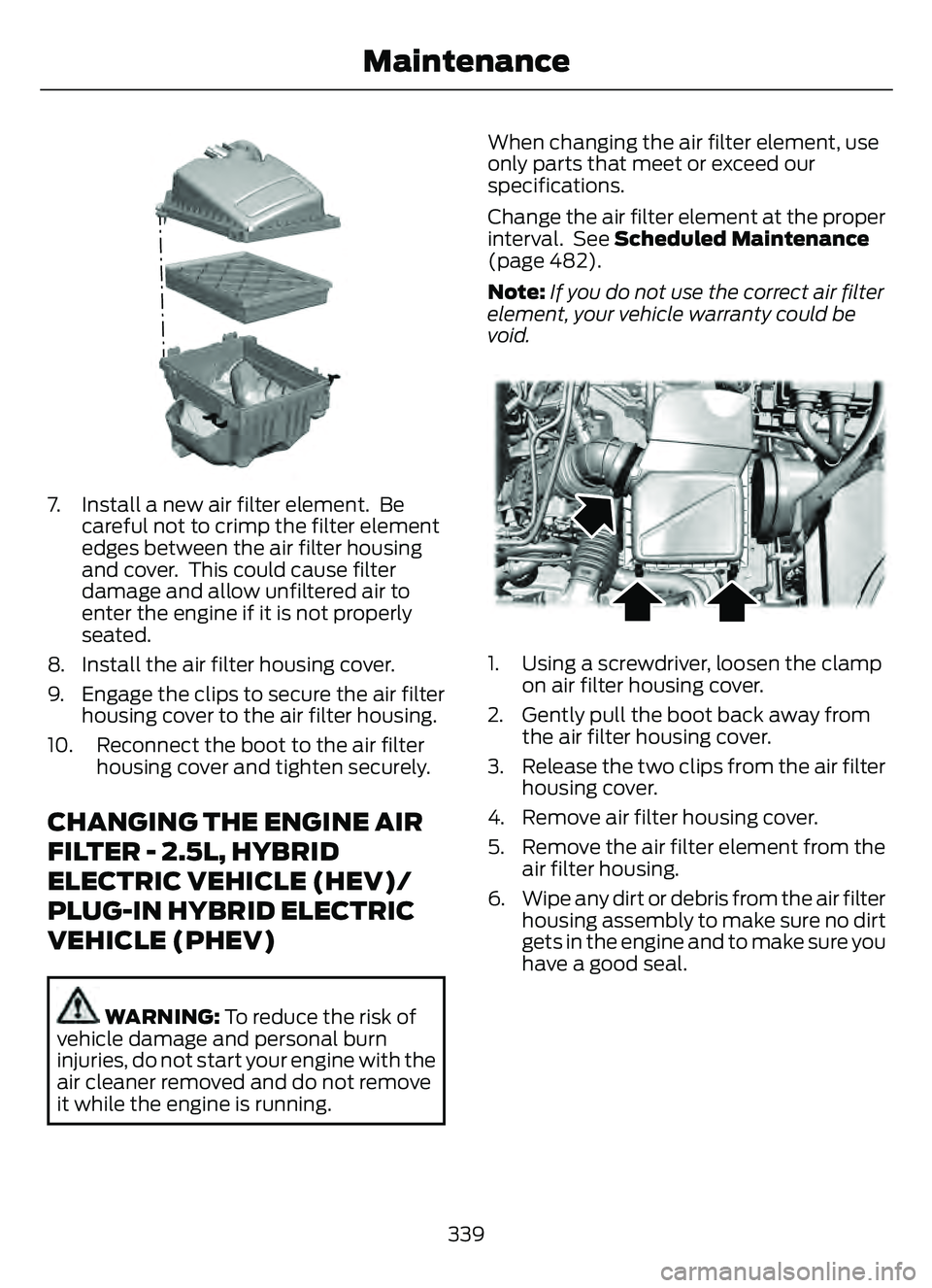
1. Using a screwdriver, loosen the clamp on air filter housing cover.
2. Gently pull the boot back away from the air filter housing cover.
3. Release the two clips from the air filter housing cover.
4. Remove air filter housing cover.
5. Remove the air filter element from the air filter housing.
6. Wipe any dirt or debris from the air filter housing assembly to make sure no dirt
gets in the engine and to make sure you
have a good seal.
339
Maintenance
Page 343 of 585
E299074E299074
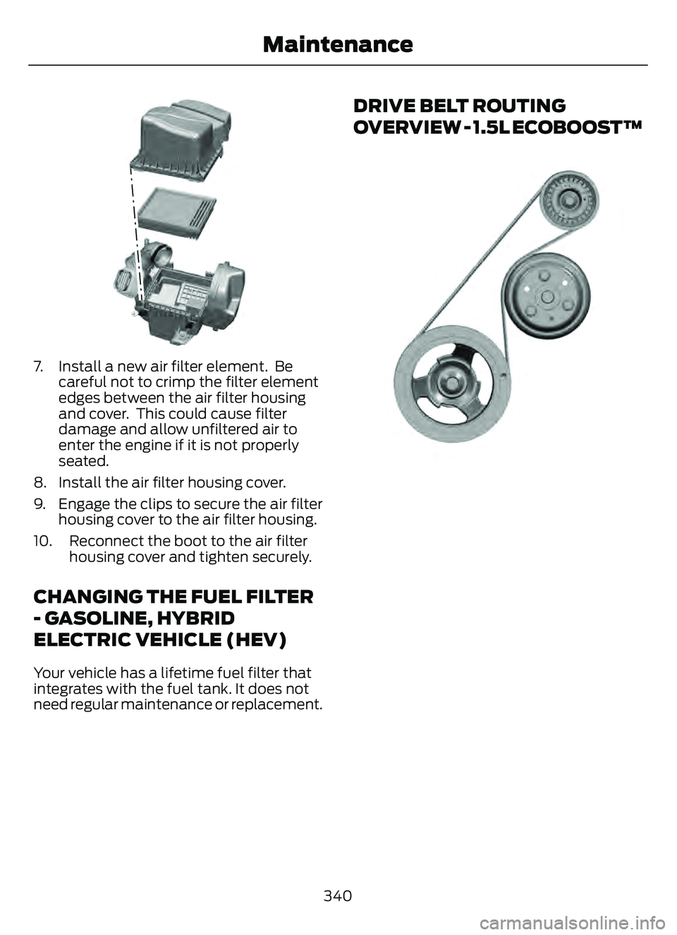
7. Install a new air filter element. Becareful not to crimp the filter element
edges between the air filter housing
and cover. This could cause filter
damage and allow unfiltered air to
enter the engine if it is not properly
seated.
8. Install the air filter housing cover.
9. Engage the clips to secure the air filter housing cover to the air filter housing.
10. Reconnect the boot to the air filter housing cover and tighten securely.
CHANGING THE FUEL FILTER
- GASOLINE, HYBRID
ELECTRIC VEHICLE (HEV)
Your vehicle has a lifetime fuel filter that
integrates with the fuel tank. It does not
need regular maintenance or replacement.
DRIVE BELT ROUTING
OVERVIEW - 1.5L ECOBOOST™
E3338613
340
Maintenance
Page 344 of 585
DRIVE BELT ROUTING
OVERVIEW - 2.0L
ECOBOOST™
E161383E161383
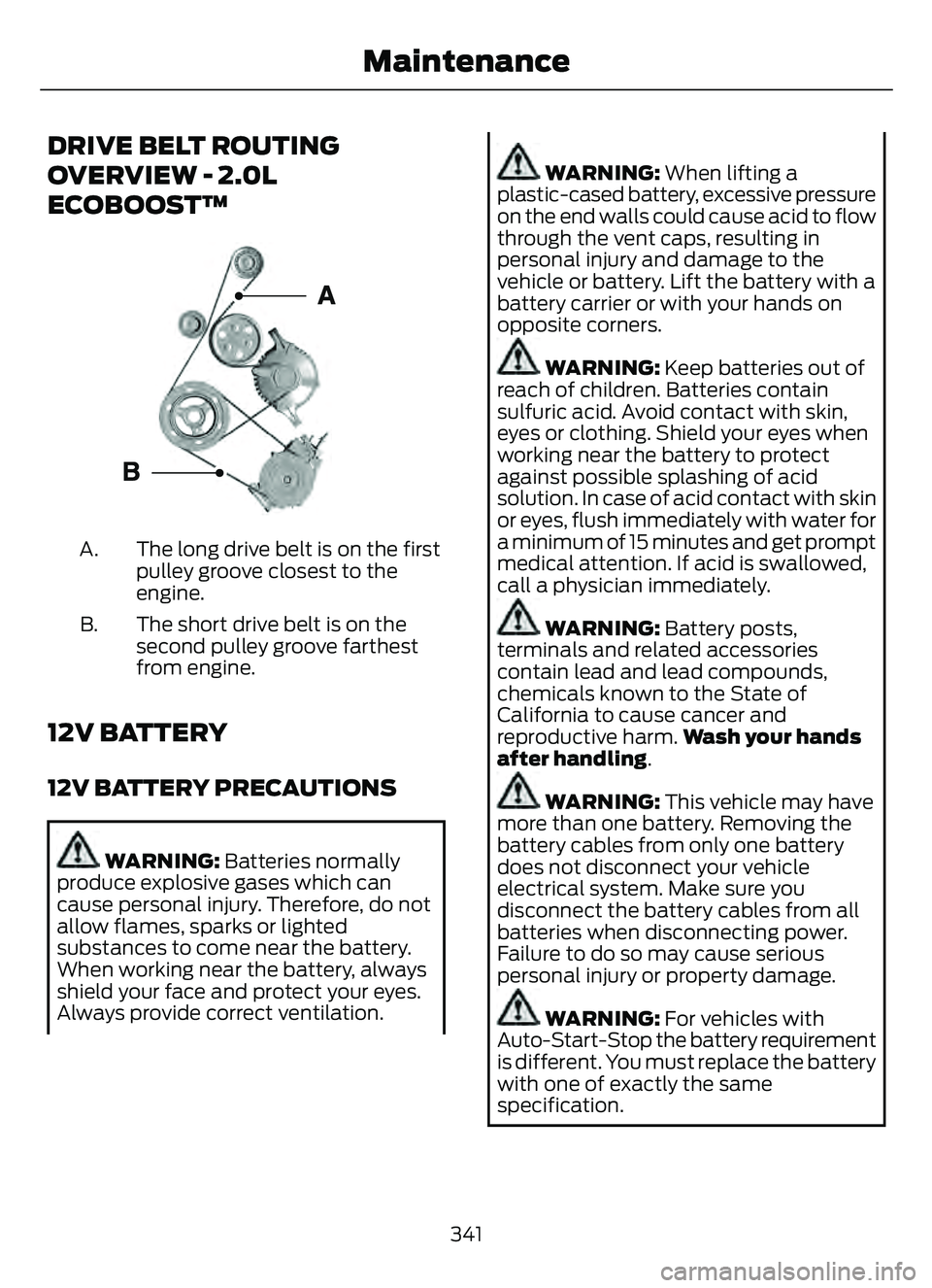
The long drive belt is on the first
pulley groove closest to the
engine.
A.
The short drive belt is on the
second pulley groove farthest
from engine.
B.
12V BATTERY
12V BATTERY PRECAUTIONS
WARNING: Batteries normally
produce explosive gases which can
cause personal injury. Therefore, do not
allow flames, sparks or lighted
substances to come near the battery.
When working near the battery, always
shield your face and protect your eyes.
Always provide correct ventilation.
WARNING: When lifting a
plastic-cased battery, excessive pressure
on the end walls could cause acid to flow
through the vent caps, resulting in
personal injury and damage to the
vehicle or battery. Lift the battery with a
battery carrier or with your hands on
opposite corners.
WARNING: Keep batteries out of
reach of children. Batteries contain
sulfuric acid. Avoid contact with skin,
eyes or clothing. Shield your eyes when
working near the battery to protect
against possible splashing of acid
solution. In case of acid contact with skin
or eyes, flush immediately with water for
a minimum of 15 minutes and get prompt
medical attention. If acid is swallowed,
call a physician immediately.
WARNING: Battery posts,
terminals and related accessories
contain lead and lead compounds,
chemicals known to the State of
California to cause cancer and
reproductive harm. Wash your hands
after handling.
WARNING: This vehicle may have
more than one battery. Removing the
battery cables from only one battery
does not disconnect your vehicle
electrical system. Make sure you
disconnect the battery cables from all
batteries when disconnecting power.
Failure to do so may cause serious
personal injury or property damage.
WARNING: For vehicles with
Auto-Start-Stop the battery requirement
is different. You must replace the battery
with one of exactly the same
specification.
341
Maintenance
Page 345 of 585
WHAT IS THE BATTERY
MANAGEMENT SYSTEM
The battery management system monitors
battery conditions and takes actions to
extend battery life.
HOW DOES THE BATTERY
MANAGEMENT SYSTEM WORK
If excessive battery drain is detected, the
system temporarily disables some
electrical systems to protect the battery.
Systems included are:
• Heated rear window.
• Heated seats.
• Climate control.
• Heated steering wheel.
• Audio unit.
• Navigation system.
A message could appear in the information
display to alert you that battery protection
actions are active. This message is only for
notification that an action is taking place,
and not intended to indicate an electrical
problem or that the battery requires
replacement.
BATTERY MANAGEMENT SYSTEM
LIMITATIONS
After battery replacement, or in some
cases after charging the battery with an
external charger, the battery management
system requires eight hours of vehicle sleep
time to relearn the battery state of charge.
During this time, your vehicle must remain
fully locked with the ignition switched off.
Note:Prior to relearning the battery state
of charge, the battery management system
could temporarily disable some electrical
systems.
Electrical Accessory Installation
To make sure the battery management
system works correctly, do not connect an
electrical device ground connection
directly to the battery negative post. This
can cause inaccurate measurements of
the battery condition and potential
incorrect system operation.
Note: If you add electrical accessories or
components to the vehicle, it could
adversely affect battery performance and
durability. This could also affect the
performance of other electrical systems in
the vehicle.
RESETTING THE BATTERY
SENSOR
When you install a new battery, reset the
battery sensor by doing the following:
1. Switch the ignition on, and leave the engine off.
Note: Complete Steps 2 and 3 within 10
seconds.
2. Flash the high beam headlamps five times, ending with the high beams off.
3. Press and release the brake pedal three times.
The battery warning lamp flashes three
times to confirm that the reset is
successful.
RECYCLING AND DISPOSING OF
THE 12V BATTERY
E107998
Make sure that you dispose of
old batteries in an
environmentally friendly way.
Seek advice from your local authority
about recycling old batteries.
342
Maintenance
Page 346 of 585
CHANGING THE 12V BATTERY
The battery is in the engine compartment.
See Under Hood Overview (page 330).
Your vehicle has a maintenance-free
battery. It does not require additional
water during service.
For longer, trouble-free operation, keep the
top of the battery clean and dry and the
battery cables tightly fastened to the
battery terminals. If any corrosion is
present on the battery or terminals, remove
the cables from the terminals and clean
with a wire brush. You can neutralize the
acid with a solution of baking soda and
water.
We recommend that you disconnect the
negative battery cable terminal from the
battery if you plan to store your vehicle for
an extended period.
Note: If you only disconnect the negative
battery cable terminal, make sure it is
isolated or placed away from the battery
terminal to avoid unintended connection or
arcing.
To maintain correct operation of the
battery management system, if you add
any electrical devices to your vehicle, do
not connect the ground connection directly
to the negative battery terminal. A
connection at the negative battery terminal
can cause inaccurate measurements of
the battery condition and potential
incorrect system operation.
Note: If you add electrical accessories or
components to your vehicle this may
adversely affect battery performance,
durability and the performance of other
electrical systems on your vehicle.
If you replace the battery make sure it
matches the electrical requirements of
your vehicle. If you disconnect or replace the battery
and your vehicle has an automatic
transmission, it must relearn its adaptive
strategy. Because of this, the transmission
may shift firmly when first driven. This is
normal operation while the transmission
fully updates its operation to optimum
shift feel.
Remove and Reinstall the Battery
To disconnect or remove the battery, do
the following:
1. Apply the parking brake and switch the
ignition off.
2. Switch all electrical equipment off, for example lights and radio.
3. Wait a minimum of two minutes before disconnecting the battery.
Note: The engine management system has
a power hold function and remains powered
for a period of time after you switch the
ignition off. This is to allow diagnostic and
adaptive tables to be stored. Disconnecting
the battery without waiting can cause
damage not covered by the vehicle
Warranty.
4. Disconnect the negative battery cable terminal.
5. Disconnect the positive battery cable terminal.
6. Remove the battery securing clamp.
7. Remove the battery.
8. To install, reverse the removal procedure.
Note: Before reconnecting the battery,
make sure the ignition remains switched off.
Note: Make sure the battery cable terminals
are fully tightened.
Note: After cleaning or replacing the
battery, make sure you reinstall the battery
cover or shield.
343
Maintenance
Page 347 of 585
If you disconnect or replace the vehicle
battery, you must reset the following
features:
• Window bounce-back. See Windows(page 105).
• Clock settings.
• Pre-set radio stations.
• Steering angle sensor.
Note: To calibrate the steering angle
sensor, drive the vehicle above 30 mph
(50 km/h) for a minimum of 1.2 mi (2 km).
Make sure to drive straight ahead for a
minimum of 30 seconds. Several vehicle
functions are disabled and a warning light
could appear until the sensor is calibrated.
ADJUSTING THE HEADLAMPS
Vertical Aim Adjustment
The headlamps on your vehicle are
properly aimed at the assembly plant. If
your vehicle has been in an accident, the
alignment of your headlamps should be
checked by your authorized dealer.
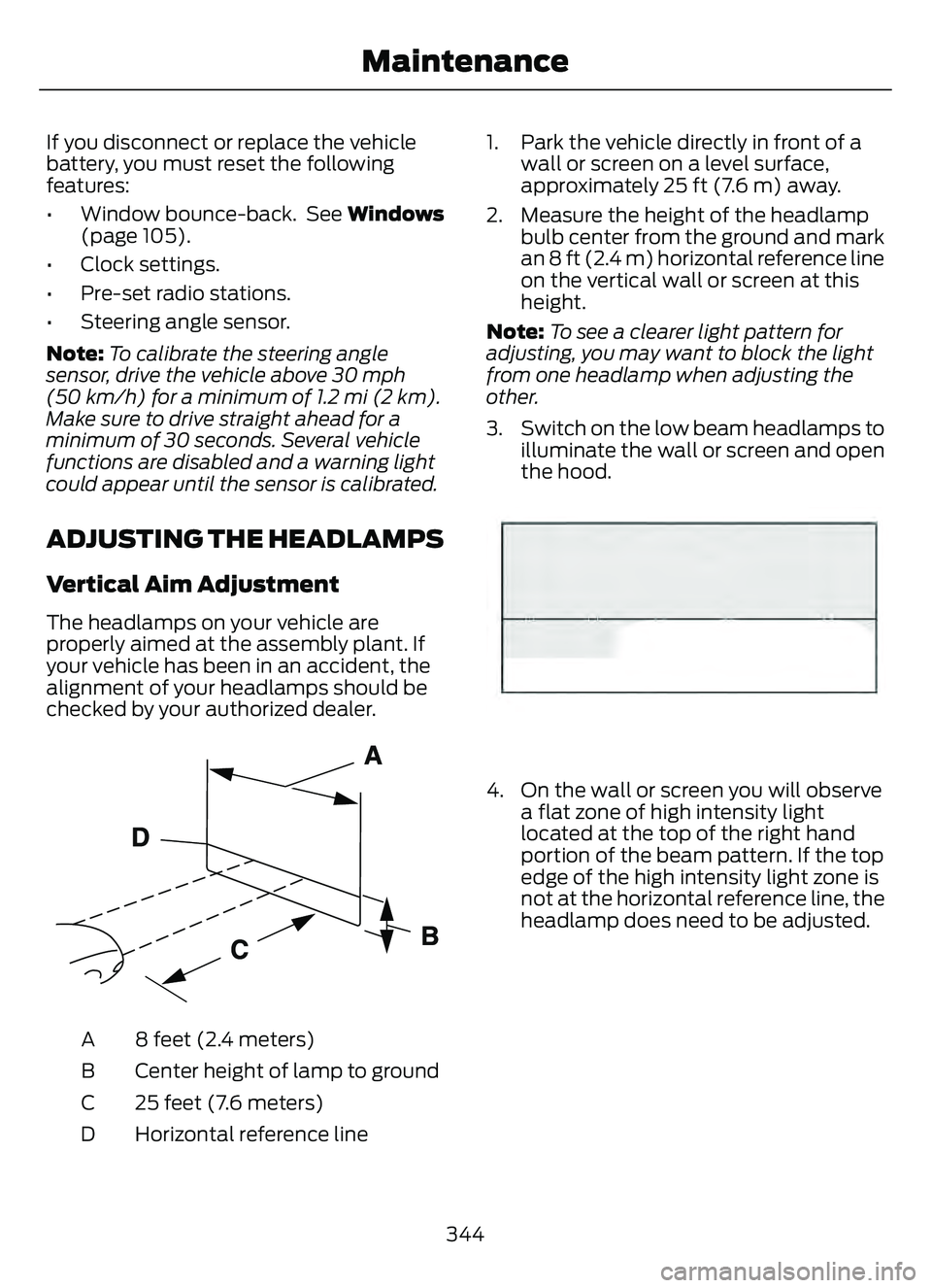
E142592
8 feet (2.4 meters)
A
Center height of lamp to ground
B
25 feet (7.6 meters)
C
Horizontal reference line
D 1. Park the vehicle directly in front of a
wall or screen on a level surface,
approximately 25 ft (7.6 m) away.
2. Measure the height of the headlamp bulb center from the ground and mark
an 8 ft (2.4 m) horizontal reference line
on the vertical wall or screen at this
height.
Note: To see a clearer light pattern for
adjusting, you may want to block the light
from one headlamp when adjusting the
other.
3. Switch on the low beam headlamps to illuminate the wall or screen and open
the hood.
E142465
4. On the wall or screen you will observea flat zone of high intensity light
located at the top of the right hand
portion of the beam pattern. If the top
edge of the high intensity light zone is
not at the horizontal reference line, the
headlamp does need to be adjusted.
344
Maintenance
Page 348 of 585
E3007889E3007889
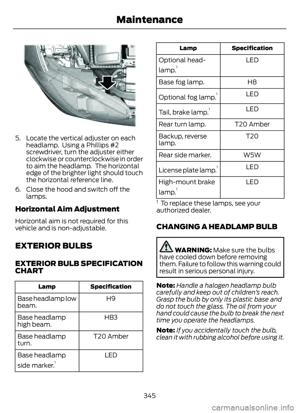
5. Locate the vertical adjuster on eachheadlamp. Using a Phillips #2
screwdriver, turn the adjuster either
clockwise or counterclockwise in order
to aim the headlamp. The horizontal
edge of the brighter light should touch
the horizontal reference line.
6. Close the hood and switch off the lamps.
Horizontal Aim Adjustment
Horizontal aim is not required for this
vehicle and is non-adjustable.
EXTERIOR BULBS
EXTERIOR BULB SPECIFICATION
CHART
Specification
Lamp
H9
Base headlamp low
beam.
HB3
Base headlamp
high beam.
T20 Amber
Base headlamp
turn.
LED
Base headlamp
side marker.
1
Specification
Lamp
LED
Optional head-
lamp.1
H8
Base fog lamp.
LED
Optional fog lamp.
1
LED
Tail, brake lamp.1
T20 Amber
Rear turn lamp.
T20
Backup, reverse
lamp.
W5W
Rear side marker.
LED
License plate lamp.
1
LED
High-mount brake
lamp.1
1 To replace these lamps, see your
authorized dealer.
CHANGING A HEADLAMP BULB
WARNING: Make sure the bulbs
have cooled down before removing
them. Failure to follow this warning could
result in serious personal injury.
Note: Handle a halogen headlamp bulb
carefully and keep out of children’s reach.
Grasp the bulb by only its plastic base and
do not touch the glass. The oil from your
hand could cause the bulb to break the next
time you operate the headlamps.
Note: If you accidentally touch the bulb,
clean it with rubbing alcohol before using it.
345
Maintenance
Page 349 of 585
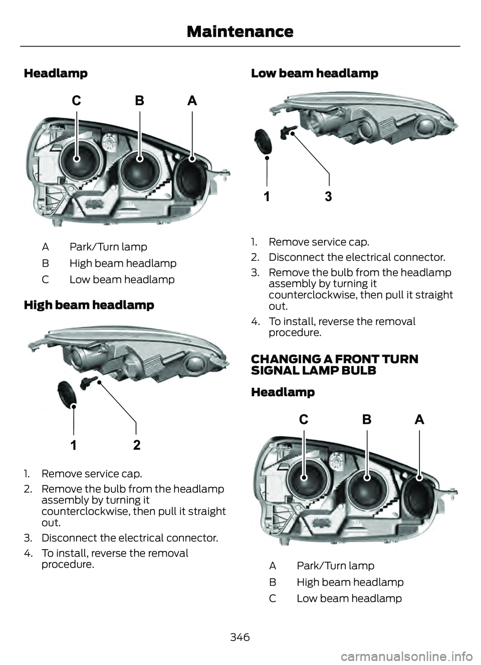
Headlamp
E307881E307881
Park/Turn lamp
A
High beam headlamp
B
Low beam headlamp
C
High beam headlamp
E307882E307882
1. Remove service cap.
2. Remove the bulb from the headlamp
assembly by turning it
counterclockwise, then pull it straight
out.
3. Disconnect the electrical connector.
4. To install, reverse the removal procedure.
Low beam headlamp
E307883E307883
1. Remove service cap.
2. Disconnect the electrical connector.
3. Remove the bulb from the headlampassembly by turning it
counterclockwise, then pull it straight
out.
4. To install, reverse the removal procedure.
CHANGING A FRONT TURN
SIGNAL LAMP BULB
Headlamp
E307881E307881
Park/Turn lamp
A
High beam headlamp
B
Low beam headlamp
C
346
Maintenance
Page 350 of 585
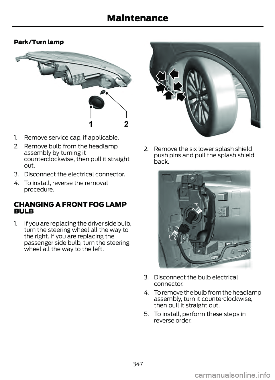
Park/Turn lamp
E307884E307884
1. Remove service cap, if applicable.
2. Remove bulb from the headlampassembly by turning it
counterclockwise, then pull it straight
out.
3. Disconnect the electrical connector.
4. To install, reverse the removal procedure.
CHANGING A FRONT FOG LAMP
BULB
1. If you are replacing the driver side bulb,turn the steering wheel all the way to
the right. If you are replacing the
passenger side bulb, turn the steering
wheel all the way to the left.
E31E3117161716
2. Remove the six lower splash shieldpush pins and pull the splash shield
back.
E31E31177151771555555555555555555555555555
3. Disconnect the bulb electricalconnector.
4. To remove the bulb from the headlamp assembly, turn it counterclockwise,
then pull it straight out.
5. To install, perform these steps in reverse order.
347
Maintenance