lock FORD ESCORT 2003 7.G User Guide
[x] Cancel search | Manufacturer: FORD, Model Year: 2003, Model line: ESCORT, Model: FORD ESCORT 2003 7.GPages: 184, PDF Size: 1.28 MB
Page 36 of 184
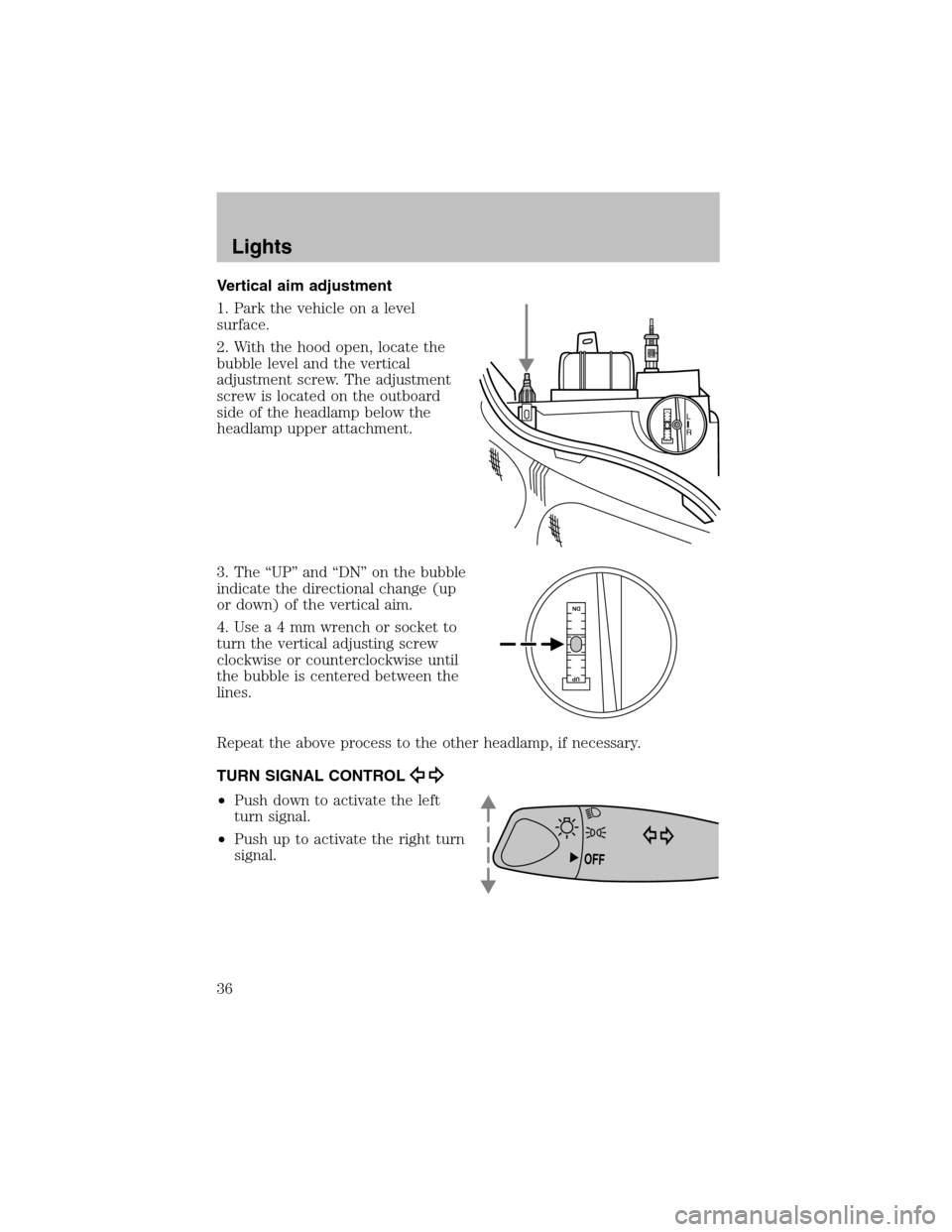
Vertical aim adjustment
1. Park the vehicle on a level
surface.
2. With the hood open, locate the
bubble level and the vertical
adjustment screw. The adjustment
screw is located on the outboard
side of the headlamp below the
headlamp upper attachment.
3. The “UP” and “DN” on the bubble
indicate the directional change (up
or down) of the vertical aim.
4. Use a 4 mm wrench or socket to
turn the vertical adjusting screw
clockwise or counterclockwise until
the bubble is centered between the
lines.
Repeat the above process to the other headlamp, if necessary.
TURN SIGNAL CONTROL
•Push down to activate the left
turn signal.
•Push up to activate the right turn
signal.
L
R
UP
DN
DNUP
OFF
Lights
36
Page 39 of 184
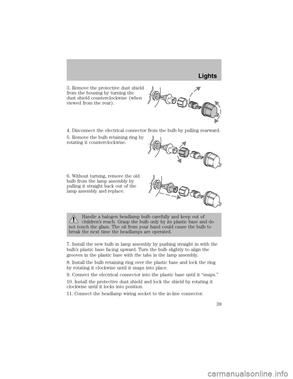
3. Remove the protective dust shield
fromthe housing by turning the
dust shield counterclockwise (when
viewed fromthe rear).
4. Disconnect the electrical connector fromthe bulb by pulling rearward.
5. Remove the bulb retaining ring by
rotating it counterclockwise.
6. Without turning, remove the old
bulb from the lamp assembly by
pulling it straight back out of the
lamp assembly and replace.
Handle a halogen headlamp bulb carefully and keep out of
children’s reach. Grasp the bulb only by its plastic base and do
not touch the glass. The oil fromyour hand could cause the bulb to
break the next time the headlamps are operated.
7. Install the new bulb in lamp assembly by pushing straight in with the
bulb’s plastic base facing upward. Turn the bulb slightly to align the
grooves in the plastic base with the tabs in the lamp assembly.
8. Install the bulb retaining ring over the plastic base and lock the ring
by rotating it clockwise until it snaps into place.
9. Connect the electrical connector into the plastic base until it “snaps.”
10. Install the protective dust shield and lock the shield by rotating it
clockwise until it locks into position.
11. Connect the headlamp wiring socket to the in-line connector.
Lights
39
Page 40 of 184
12. Turn the headlamps on and make sure they work properly. If the
headlamp was correctly aligned before you changed the bulb, you should
not need to align it again.
Replacing front parking lamp/turn signal bulbs
1. Make sure the headlamp switch is in the OFF position.
2. Open the hood and disconnect the headlamp wiring socket from the
in-line connector. This will make it easier to change the bulb.
3. Remove the protective dust shield from the housing by turning the
dust shield counterclockwise (when viewed fromthe rear).
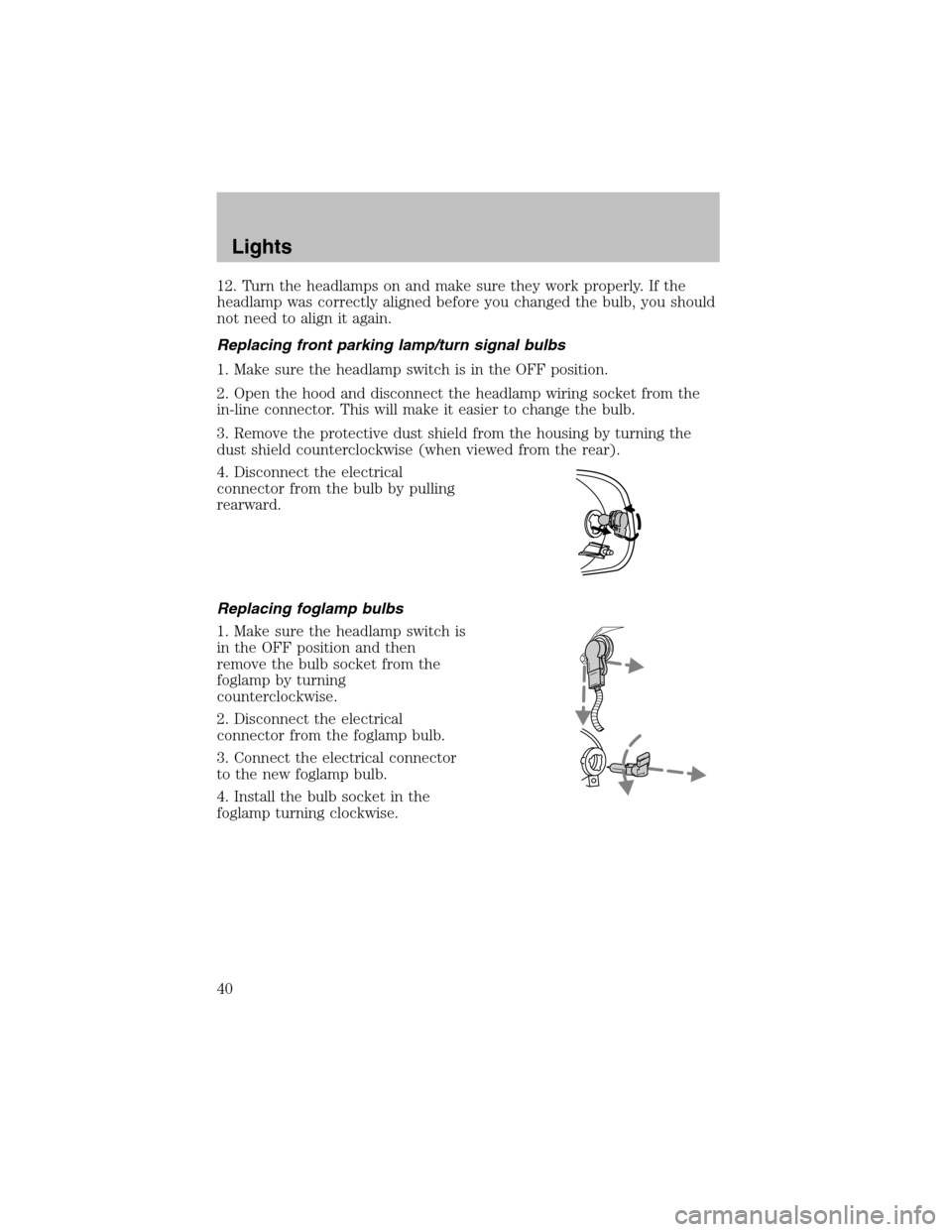
4. Disconnect the electrical
connector fromthe bulb by pulling
rearward.
Replacing foglamp bulbs
1. Make sure the headlamp switch is
in the OFF position and then
remove the bulb socket from the
foglamp by turning
counterclockwise.
2. Disconnect the electrical
connector fromthe foglamp bulb.
3. Connect the electrical connector
to the new foglamp bulb.
4. Install the bulb socket in the
foglamp turning clockwise.
Lights
40
Page 41 of 184
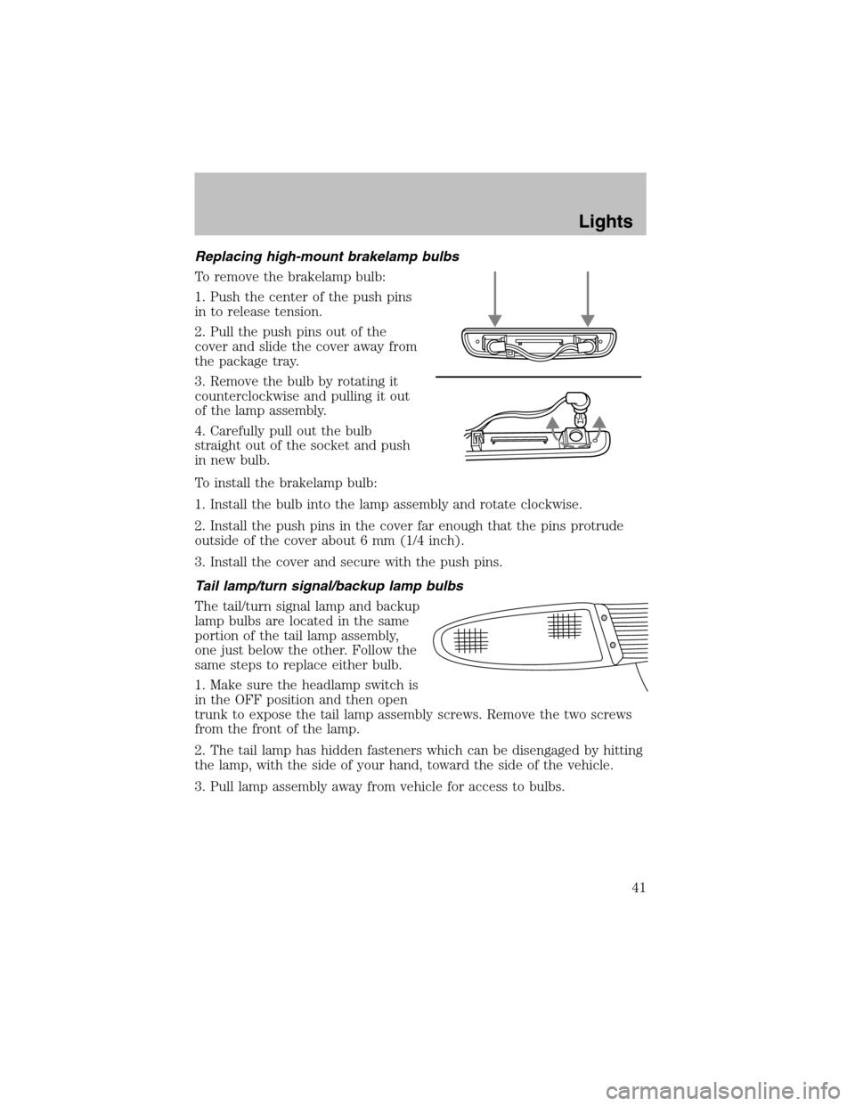
Replacing high-mount brakelamp bulbs
To remove the brakelamp bulb:
1. Push the center of the push pins
in to release tension.
2. Pull the push pins out of the
cover and slide the cover away from
the package tray.
3. Remove the bulb by rotating it
counterclockwise and pulling it out
of the lamp assembly.
4. Carefully pull out the bulb
straight out of the socket and push
in new bulb.
To install the brakelamp bulb:
1. Install the bulb into the lamp assembly and rotate clockwise.
2. Install the push pins in the cover far enough that the pins protrude
outside of the cover about 6 mm (1/4 inch).
3. Install the cover and secure with the push pins.
Tail lamp/turn signal/backup lamp bulbs
The tail/turn signal lamp and backup
lamp bulbs are located in the same
portion of the tail lamp assembly,
one just below the other. Follow the
same steps to replace either bulb.
1. Make sure the headlamp switch is
in the OFF position and then open
trunk to expose the tail lamp assembly screws. Remove the two screws
fromthe front of the lamp.
2. The tail lamp has hidden fasteners which can be disengaged by hitting
the lamp, with the side of your hand, toward the side of the vehicle.
3. Pull lamp assembly away from vehicle for access to bulbs.
Lights
41
Page 42 of 184
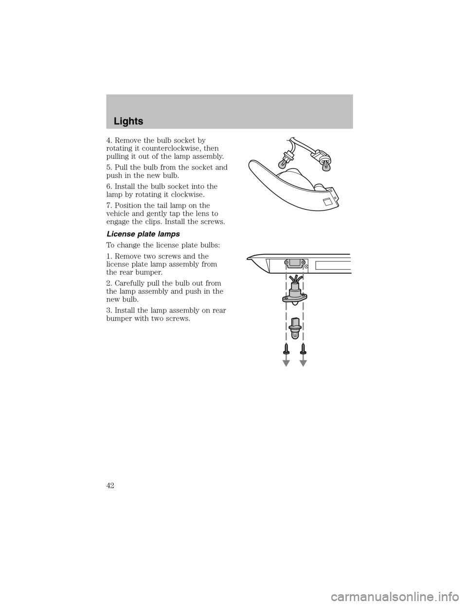
4. Remove the bulb socket by
rotating it counterclockwise, then
pulling it out of the lamp assembly.
5. Pull the bulb fromthe socket and
push in the new bulb.
6. Install the bulb socket into the
lamp by rotating it clockwise.
7. Position the tail lamp on the
vehicle and gently tap the lens to
engage the clips. Install the screws.
License plate lamps
To change the license plate bulbs:
1. Remove two screws and the
license plate lamp assembly from
the rear bumper.
2. Carefully pull the bulb out from
the lamp assembly and push in the
new bulb.
3. Install the lamp assembly on rear
bumper with two screws.
Lights
42
Page 44 of 184
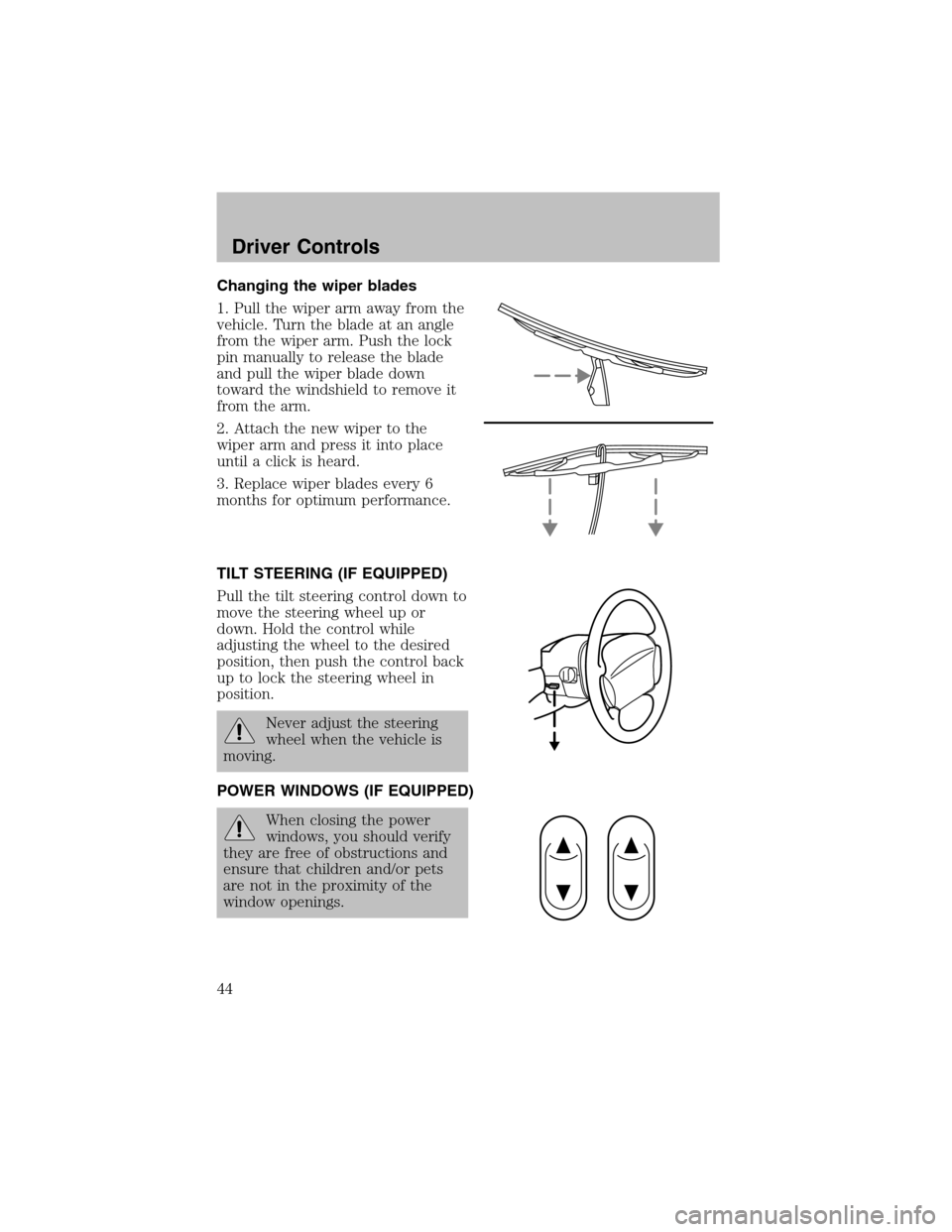
Changing the wiper blades
1. Pull the wiper armaway fromthe
vehicle. Turn the blade at an angle
fromthe wiper arm. Push the lock
pin manually to release the blade
and pull the wiper blade down
toward the windshield to remove it
fromthe arm.
2. Attach the new wiper to the
wiper armand press it into place
until a click is heard.
3. Replace wiper blades every 6
months for optimum performance.
TILT STEERING (IF EQUIPPED)
Pull the tilt steering control down to
move the steering wheel up or
down. Hold the control while
adjusting the wheel to the desired
position, then push the control back
up to lock the steering wheel in
position.
Never adjust the steering
wheel when the vehicle is
moving.
POWER WINDOWS (IF EQUIPPED)
When closing the power
windows, you should verify
they are free of obstructions and
ensure that children and/or pets
are not in the proximity of the
window openings.
Driver Controls
44
Page 50 of 184
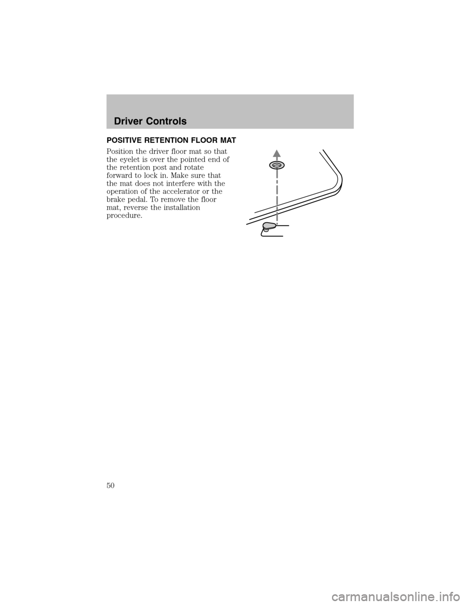
POSITIVE RETENTION FLOOR MAT
Position the driver floor mat so that
the eyelet is over the pointed end of
the retention post and rotate
forward to lock in. Make sure that
the mat does not interfere with the
operation of the accelerator or the
brake pedal. To remove the floor
mat, reverse the installation
procedure.
Driver Controls
50
Page 51 of 184
KEYS
The key operates all locks on your vehicle. In case of loss, replacement
keys are available fromyour dealer.
You should always carry a second key with you in a safe place in case
you require it in an emergency.
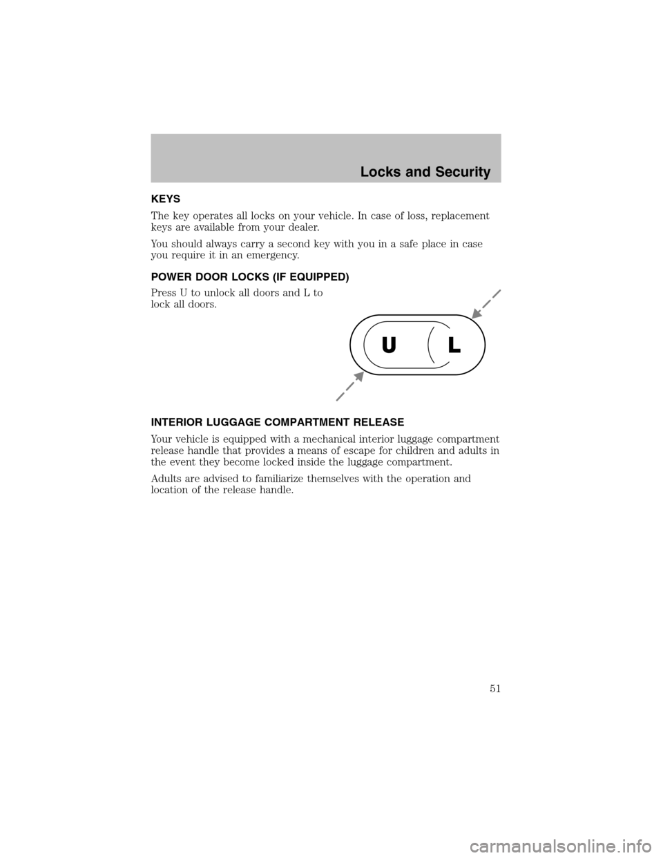
POWER DOOR LOCKS (IF EQUIPPED)
Press U to unlock all doors and L to
lock all doors.
INTERIOR LUGGAGE COMPARTMENT RELEASE
Your vehicle is equipped with a mechanical interior luggage compartment
release handle that provides a means of escape for children and adults in
the event they become locked inside the luggage compartment.
Adults are advised to familiarize themselves with the operation and
location of the release handle.
UL
Locks and Security
51
Page 52 of 184
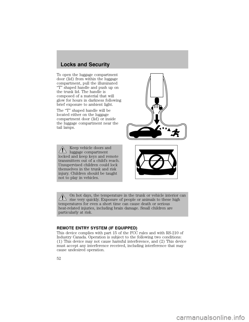
To open the luggage compartment
door (lid) fromwithin the luggage
compartment, pull the illuminated
“T” shaped handle and push up on
the trunk lid. The handle is
composed of a material that will
glow for hours in darkness following
brief exposure to ambient light.
The “T” shaped handle will be
located either on the luggage
compartment door (lid) or inside
the luggage compartment near the
tail lamps.
Keep vehicle doors and
luggage compartment
locked and keep keys and remote
transmitters out of a child’s reach.
Unsupervised children could lock
themselves in the trunk and risk
injury. Children should be taught
not to play in vehicles.
On hot days, the temperature in the trunk or vehicle interior can
rise very quickly. Exposure of people or animals to these high
temperatures for even a short time can cause death or serious
heat-related injuries, including brain damage. Small children are
particularly at risk.
REMOTE ENTRY SYSTEM (IF EQUIPPED)
This device complies with part 15 of the FCC rules and with RS-210 of
Industry Canada. Operation is subject to the following two conditions:
(1) This device may not cause harmful interference, and (2) This device
must accept any interference received, including interference that may
cause undesired operation.
Locks and Security
52
Page 53 of 184

Changes or modifications not expressly approved by the party
responsible for compliance could void the user’s authority to
operate the equipment.
Your vehicle may have an all-door remote entry system or a driver’s door
only remote entry system.
The all-door remote entry system
allows you to:
•lock or unlock all vehicle doors
without a key.
•armand disarmthe anti-theft
system. (For more information on
the anti-theft system, refer to
Anti-theft systemin this
chapter.)
•open the trunk.
•activate the panic alarm.
The driver’s door only entry systemallows you to:
•lock the driver’s door
•unlock the driver’s door only without a key.
•activate the panic alarm.
•open the trunk
The remote entry features only operate with the ignition in the LOCK
position.
If there is any potential remote keyless entry problem with your vehicle,
ensureALL remote entry transmittersare brought to the dealership,
to aid in troubleshooting.
Unlocking the doors
1. Pressand release to unlock the driver’s door.Note:The interior
lamps will illuminate.
2. With the all-door remote entry, press
and release again within
three seconds to unlock all the doors.
The remote entry system activates the illuminated entry feature. This
feature turns on the interior lamps for 20 seconds or until the ignition is
turned to the ON position. The dome lamp control must be set to the
DOORposition in order for the illuminated entry feature to operate.
Locks and Security
53