engine FORD EXCURSION 2004 1.G Owners Manual
[x] Cancel search | Manufacturer: FORD, Model Year: 2004, Model line: EXCURSION, Model: FORD EXCURSION 2004 1.GPages: 272, PDF Size: 1.82 MB
Page 3 of 272
Cleaning 213
Underbody preservation 217
Maintenance and Specifications 219
Hood 220
Engine compartment 221
Engine oil 222
Battery 225
Fuel information 233
Air filter(s) 248
Part numbers 254
Refill capacities 254
Lubricant specifications 257
Engine data 259
Vehicle dimensions 260
Accessories 263
Index 266
All rights reserved. Reproduction by any means, electronic or mechanical
including photocopying, recording or by any information storage and retrieval
system or translation in whole or part is not permitted without written
authorization from Ford Motor Company. Ford may change the contents without
notice and without incurring obligation.
Copyright © 2002 Ford Motor Company
Table of Contents
3
Page 4 of 272
The following warning may be required by California law:
CALIFORNIA Proposition 65 Warning
WARNING:Engine exhaust, some of its constituents, and
certain vehicle components contain or emit chemicals known to
the State of California to cause cancer and birth defects or other
reproductive harm. In addition, certain fluids contained in vehicles and
certain products of component wear contain or emit chemicals known
to the State of California to cause cancer and birth defects or other
reproductive harm.
CONGRATULATIONS
Congratulations on acquiring your new Ford. Please take the time to get
well acquainted with your vehicle by reading this handbook. The more
you know and understand about your vehicle the greater the safety and
pleasure you will derive from driving it.
For more information on Ford Motor Company and its products visit the
following website:
•In the United States: www.ford.com
•In Canada: www.ford.ca
•In Australia: www.ford.com.au
•In Mexico: www.ford.com.mx
Additional owner information is given in separate publications.
This Owner’s Guide describes every option and model variant available
and therefore some of the items covered may not apply to your
particular vehicle. Furthermore, due to printing cycles it may describe
options before they are generally available.
Remember to pass on the Owner’s Guide when reselling the vehicle. It is
an integral part of the vehicle.
Fuel pump shut-off switchIn the event of an accident the
safety switch will automatically cut off the fuel supply to the
engine. The switch can also be activated through sudden vibration (e.g.
collision when parking). To reset the switch, refer to theFuel pump
shut-off switchin theRoadside emergencieschapter.
Introduction
4
Page 6 of 272
SPECIAL NOTICES
Emission warranty
The New Vehicle Limited Warranty includes Bumper-to-Bumper
Coverage, Safety Restraint Coverage, Corrosion Coverage, and 7.3L
Power Stroke Diesel Engine Coverage. In addition, your vehicle is eligible
for Emissions Defect and Emissions Performance Warranties. For a
detailed description of what is covered and what is not covered, refer to
theWarranty Guidethat is provided to you along with your Owner’s
Guide.
Special instructions
For your added safety, your vehicle is fitted with sophisticated electronic
controls.
By operating other electronic equipment (e.g. mobile telephone
without exterior aerial) electromagnetic fields can occur which
can cause malfunctions of the vehicle electronics. Therefore you should
observe the instructions of the equipment manufacturers.
Please read the sectionAir bagin theSeating and safety
restraintschapter. Failure to follow the specific warnings and
instructions could result in personal injury.
Front seat mounted rear-facing child or baby seats should
NEVERbe used in front of a passenger side air bag.
Introduction
6
Page 9 of 272
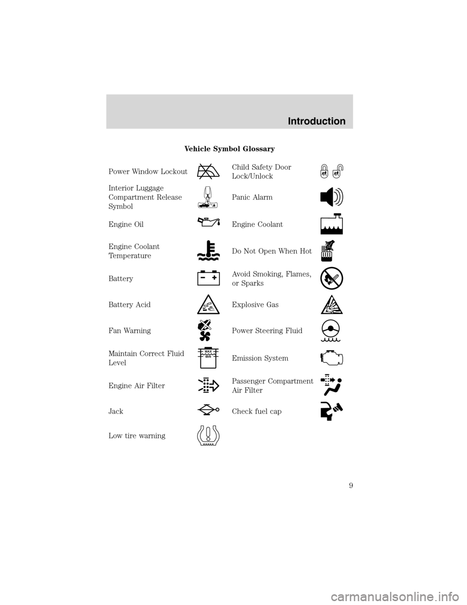
Vehicle Symbol Glossary
Power Window Lockout
Child Safety Door
Lock/Unlock
Interior Luggage
Compartment Release
Symbol
Panic Alarm
Engine OilEngine Coolant
Engine Coolant
TemperatureDo Not Open When Hot
BatteryAvoid Smoking, Flames,
or Sparks
Battery AcidExplosive Gas
Fan WarningPower Steering Fluid
Maintain Correct Fluid
LevelMAX
MIN
Emission System
Engine Air FilterPassenger Compartment
Air Filter
JackCheck fuel cap
Low tire warning
Introduction
9
Page 10 of 272
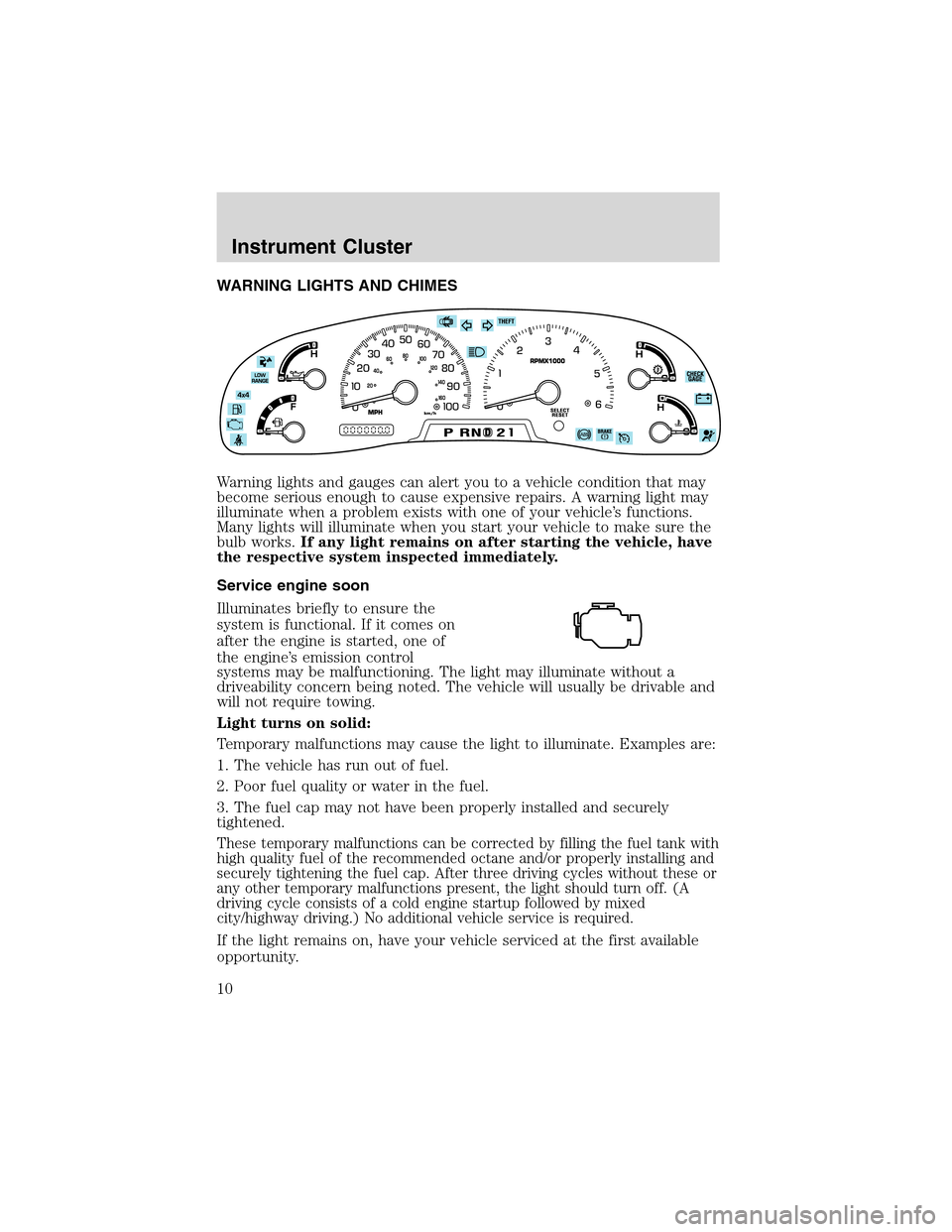
WARNING LIGHTS AND CHIMES
Warning lights and gauges can alert you to a vehicle condition that may
become serious enough to cause expensive repairs. A warning light may
illuminate when a problem exists with one of your vehicle’s functions.
Many lights will illuminate when you start your vehicle to make sure the
bulb works.If any light remains on after starting the vehicle, have
the respective system inspected immediately.
Service engine soon
Illuminates briefly to ensure the
system is functional. If it comes on
after the engine is started, one of
the engine’s emission control
systems may be malfunctioning. The light may illuminate without a
driveability concern being noted. The vehicle will usually be drivable and
will not require towing.
Light turns on solid:
Temporary malfunctions may cause the light to illuminate. Examples are:
1. The vehicle has run out of fuel.
2. Poor fuel quality or water in the fuel.
3. The fuel cap may not have been properly installed and securely
tightened.
These temporary malfunctions can be corrected by filling the fuel tank with
high quality fuel of the recommended octane and/or properly installing and
securely tightening the fuel cap. After three driving cycles without these or
any other temporary malfunctions present, the light should turn off. (A
driving cycle consists of a cold engine startup followed by mixed
city/highway driving.) No additional vehicle service is required.
If the light remains on, have your vehicle serviced at the first available
opportunity.
Instrument Cluster
10
Page 11 of 272
Light is blinking:
Engine misfire is occurring which could damage your catalytic converter.
You should drive in a moderate fashion (avoid heavy acceleration and
deceleration) and have your vehicle serviced at the first available
opportunity.
Under engine misfire conditions, excessive exhaust temperatures
could damage the catalytic converter, the fuel system, interior
floor coverings or other vehicle components, possibly causing a fire.
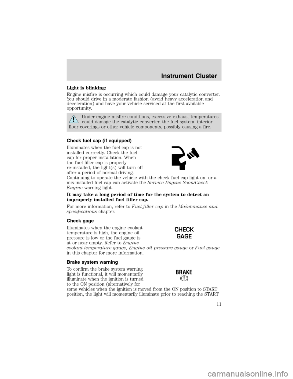
Check fuel cap (if equipped)
Illuminates when the fuel cap is not
installed correctly. Check the fuel
cap for proper installation. When
the fuel filler cap is properly
re-installed, the light(s) will turn off
after a period of normal driving.
Continuing to operate the vehicle with the check fuel cap light on, or a
mis-installed fuel cap can activate theService Engine Soon/Check
Enginewarning light.
It may take a long period of time for the system to detect an
improperly installed fuel filler cap.
For more information, refer toFuel filler capin theMaintenance and
specificationschapter.
Check gage
Illuminates when the engine coolant
temperature is high, the engine oil
pressure is low or the fuel gauge is
at or near empty. Refer toEngine
coolant temperature gauge, Engine oil pressure gaugeorFuel gauge
in this chapter for more information.
Brake system warning
To confirm the brake system warning
light is functional, it will momentarily
illuminate when the ignition is turned
to the ON position (alternatively for
some vehicles when the ignition is moved from the ON position to START
position, the light will momentarily illuminate prior to reaching the START
CHECK
GAGE
Instrument Cluster
11
Page 15 of 272
Key-in-ignition warning chime
Sounds when the key is left in the ignition and the driver’s door is
opened.
Parking brake ON warning chime
Sounds when the parking brake is set, the engine is running and the
vehicle is driven more than 5 Km (3 mph).
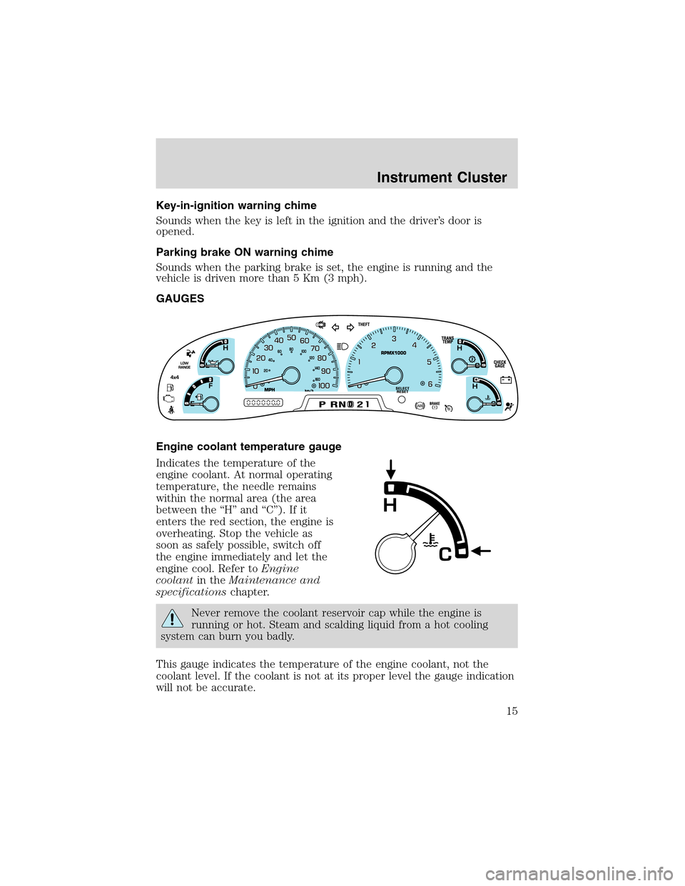
GAUGES
Engine coolant temperature gauge
Indicates the temperature of the
engine coolant. At normal operating
temperature, the needle remains
within the normal area (the area
between the “H” and “C”). If it
enters the red section, the engine is
overheating. Stop the vehicle as
soon as safely possible, switch off
the engine immediately and let the
engine cool. Refer toEngine
coolantin theMaintenance and
specificationschapter.
Never remove the coolant reservoir cap while the engine is
running or hot. Steam and scalding liquid from a hot cooling
system can burn you badly.
This gauge indicates the temperature of the engine coolant, not the
coolant level. If the coolant is not at its proper level the gauge indication
will not be accurate.
Instrument Cluster
15
Page 16 of 272
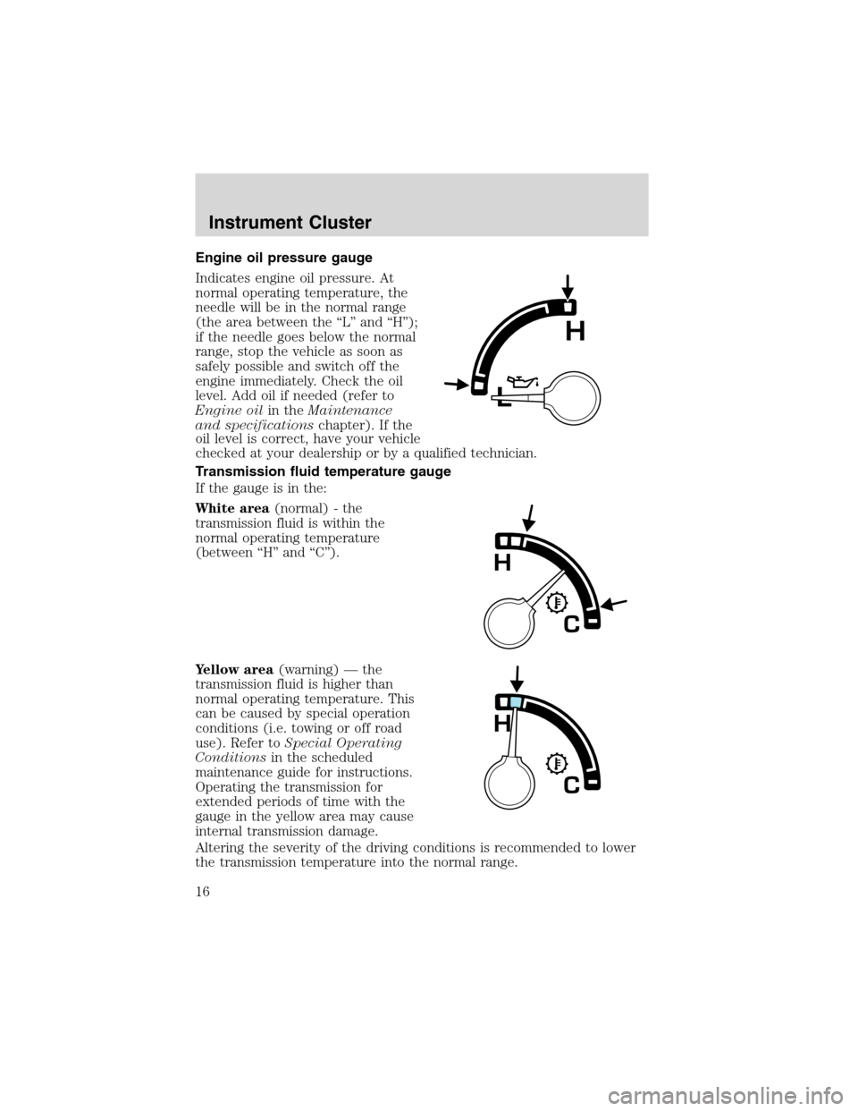
Engine oil pressure gauge
Indicates engine oil pressure. At
normal operating temperature, the
needle will be in the normal range
(the area between the “L” and “H”);
if the needle goes below the normal
range, stop the vehicle as soon as
safely possible and switch off the
engine immediately. Check the oil
level. Add oil if needed (refer to
Engine oilin theMaintenance
and specificationschapter). If the
oil level is correct, have your vehicle
checked at your dealership or by a qualified technician.
Transmission fluid temperature gauge
If the gauge is in the:
White area(normal) - the
transmission fluid is within the
normal operating temperature
(between “H” and “C”).
Yellow area(warning) — the
transmission fluid is higher than
normal operating temperature. This
can be caused by special operation
conditions (i.e. towing or off road
use). Refer toSpecial Operating
Conditionsin the scheduled
maintenance guide for instructions.
Operating the transmission for
extended periods of time with the
gauge in the yellow area may cause
internal transmission damage.
Altering the severity of the driving conditions is recommended to lower
the transmission temperature into the normal range.
Instrument Cluster
16
Page 18 of 272
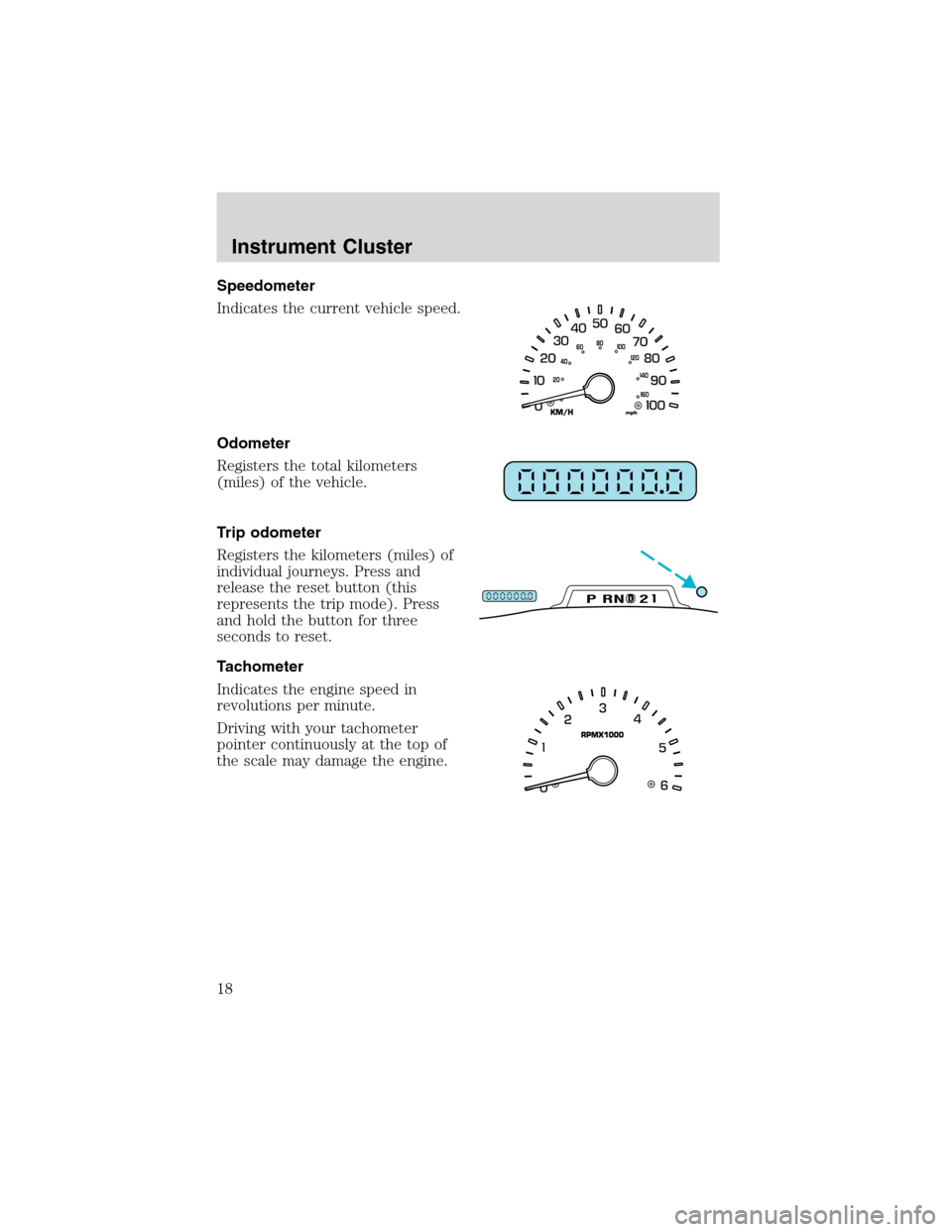
Speedometer
Indicates the current vehicle speed.
Odometer
Registers the total kilometers
(miles) of the vehicle.
Trip odometer
Registers the kilometers (miles) of
individual journeys. Press and
release the reset button (this
represents the trip mode). Press
and hold the button for three
seconds to reset.
Tachometer
Indicates the engine speed in
revolutions per minute.
Driving with your tachometer
pointer continuously at the top of
the scale may damage the engine.
DPRND2
Instrument Cluster
18
Page 51 of 272
General operating tips
•When the engine is not running, use the system sparingly otherwise it
will run the battery down.
•When the ignition is turned to OFF, the Rear Seat Entertainment DVD
System is also turned OFF. When the ignition is turned ON, the
system will begin playback from the last selected media source when
the play control is pressed.
•To disable the DVD player, simultaneously press the 3 and 5 memory
presets on the radio face. To enable the DVD player again, press the 3
and 5 presets simultaneously.
•The DVD player is only capable of reading the bottom side of a disc.
When inserting a single sided disc, the label should be up. For a
multi-sided disc, the desired play side should be down when the disc
is inserted into the player.
•The DVD player is only capable of playback of DVDs and CDs. The
player is not compatible with CDR/RW media.
•DVDs are formatted by regions. This DVD system can only play region
1 DVDs (DVDs manufactured in U.S and Canada).
This unit is designed to play commercially pressed 12 cm (4.75
in) audio compact discs and DVDs only. Due to technical
incompatibility, certain recordable and re-recordable compact
discs may not function correctly when used in Ford DVD/CD
players. Irregular shaped discs, discs with a scratch protection
film attached, and discs with homemade paper (adhesive) labels
should not be inserted into the player. The label may peel and
cause the disc to become jammed. It is recommended that
homemade discs be identified with permanent felt tip marker
rather than adhesive labels. Ball point pens may damage discs.
Please contact your dealer for further information.
Inserting a CD/DVD
Inserting a CD/DVD into the DVD player automatically turns the power
ON and playback should begin.
The counter is automatically reset to 0:00:00.
Ensure that the overhead screen is down for viewing.
Removing a CD/DVD
1. Press the STOP/EJECT control to stop playback.
2. Press the STOP/EJECT control again to eject the CD/DVD.
Entertainment Systems
51