engine FORD EXCURSION 2004 1.G Owner's Guide
[x] Cancel search | Manufacturer: FORD, Model Year: 2004, Model line: EXCURSION, Model: FORD EXCURSION 2004 1.GPages: 272, PDF Size: 1.82 MB
Page 180 of 272
TRAILER TOWING
Your vehicle may tow a
Conventional/Class IV trailer
provided the maximum trailer
weight is less than or equal to the
maximum trailer weight listed for
your engine and rear axle ratio on
the following charts.
Your vehicle’s load capacity is designated by weight, not by volume, so
you cannot necessarily use all available space when loading a vehicle.
Towing a trailer places an additional load on your vehicle’s engine,
transmission, axle, brakes, tires and suspension. Inspect these
components carefully after any towing operation. The following trailer
towing charts apply to vehicles equipped with gasoline engines; for
Diesel engines, refer to the7.3 Liter Power Stroke Direct Injection
Turbo Diesel Supplement.
The hitch receiver was designed not to be removed. Any
modification or removal of the hitch receiver compromises the
safety benefit it was designed to provide.
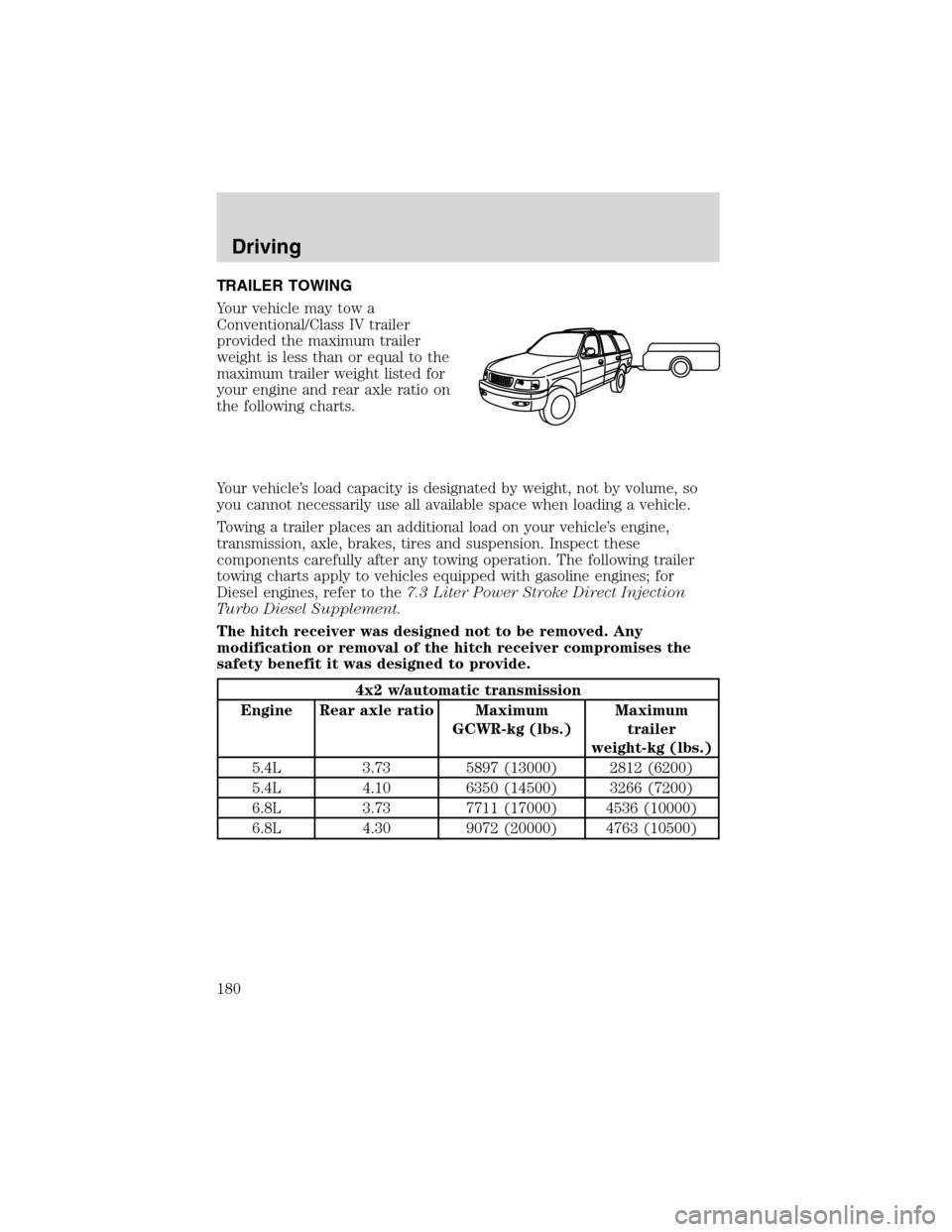
4x2 w/automatic transmission
Engine Rear axle ratio Maximum
GCWR-kg (lbs.)Maximum
trailer
weight-kg (lbs.)
5.4L 3.73 5897 (13000) 2812 (6200)
5.4L 4.10 6350 (14500) 3266 (7200)
6.8L 3.73 7711 (17000) 4536 (10000)
6.8L 4.30 9072 (20000) 4763 (10500)
Driving
180
Page 181 of 272
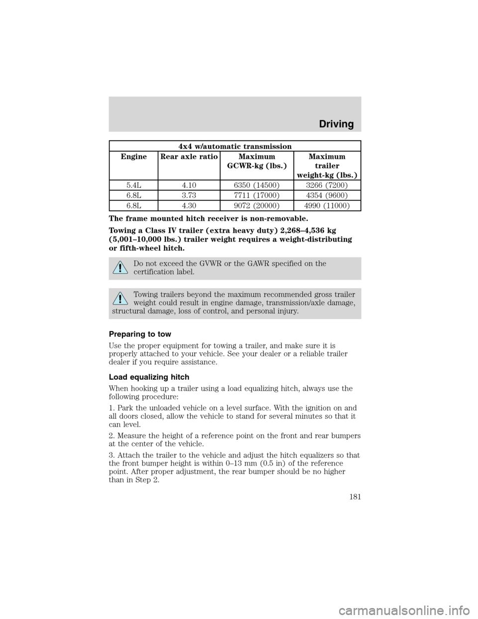
4x4 w/automatic transmission
Engine Rear axle ratio Maximum
GCWR-kg (lbs.)Maximum
trailer
weight-kg (lbs.)
5.4L 4.10 6350 (14500) 3266 (7200)
6.8L 3.73 7711 (17000) 4354 (9600)
6.8L 4.30 9072 (20000) 4990 (11000)
The frame mounted hitch receiver is non-removable.
Towing a Class IV trailer (extra heavy duty) 2,268–4,536 kg
(5,001–10,000 lbs.) trailer weight requires a weight-distributing
or fifth-wheel hitch.
Do not exceed the GVWR or the GAWR specified on the
certification label.
Towing trailers beyond the maximum recommended gross trailer
weight could result in engine damage, transmission/axle damage,
structural damage, loss of control, and personal injury.
Preparing to tow
Use the proper equipment for towing a trailer, and make sure it is
properly attached to your vehicle. See your dealer or a reliable trailer
dealer if you require assistance.
Load equalizing hitch
When hooking up a trailer using a load equalizing hitch, always use the
following procedure:
1. Park the unloaded vehicle on a level surface. With the ignition on and
all doors closed, allow the vehicle to stand for several minutes so that it
can level.
2. Measure the height of a reference point on the front and rear bumpers
at the center of the vehicle.
3. Attach the trailer to the vehicle and adjust the hitch equalizers so that
the front bumper height is within 0–13 mm (0.5 in) of the reference
point. After proper adjustment, the rear bumper should be no higher
than in Step 2.
Driving
181
Page 183 of 272
Driving while you tow
When towing a trailer:
•Ensure that you turn off your speed control. The speed control may
shut off automatically when you are towing on long, steep grades.
•Consult your local motor vehicle speed regulations for towing a trailer.
•To eliminate excessive shifting, use a lower gear. This will also assist
in transmission cooling. (For additional information, refer to the
Driving with a 4–speed automatic transmissionsection in this
chapter.
•Anticipate stops and brake gradually.
•Do not exceed the GCWR rating or transmission damage may occur.
Servicing after towing
If you tow a trailer for long distances, your vehicle will require more
frequent service intervals. Refer to your scheduled maintenance guide for
more information.
Trailer towing tips
•Practice turning, stopping and backing up before starting on a trip to
get the feel of the vehicle trailer combination. When turning, make
wider turns so the trailer wheels will clear curbs and other obstacles.
•Allow more distance for stopping with a trailer attached.
•The trailer tongue weight should be no more than 10–15% of the
loaded trailer weight.
•After you have traveled 80 km (50 miles), thoroughly check your
hitch, electrical connections and trailer wheel lug nuts.
•To aid in engine/transmission cooling and A/C efficiency during hot
weather while stopped in traffic, place the gearshift lever in P (Park)
(automatic transmission) or N (Neutral) (manual transmissions).
•Vehicles with trailers should not be parked on a grade. If you must
park on a grade, place wheel chocks under the trailer’s wheels.
Launching or retrieving a boat
When backing down a ramp during boat launching or retrieval,
•Do not allow the static water level to rise above the bottom edge of
the rear bumper.
•Do not allow waves to break higher than 15 cm (6 inches) above the
bottom edge of the rear bumper.
Driving
183
Page 186 of 272
U.S. Ford or Mercury vehicle customers who require roadside assistance,
call 1–800–241–3673; Lincoln vehicle customers call 1–800–521–4140.
Canadian customers who require roadside assistance, call
1–800–665–2006.
If you need to arrange roadside assistance for yourself, Ford Motor
Company will reimburse a reasonable amount. To obtain reimbursement
information, U.S. Ford or Mercury vehicles customers call
1-800-241-3673; Lincoln vehicle customers call 1–800–521–4140.
Canadian customers who need to obtain reimbursement information, call
1–800–665–2006.
ROADSIDE COVERAGE BEYOND BASIC WARRANTY
In the United States, you may purchase additional roadside assistance
coverage beyond this period through the Ford Auto Club by contacting
your Ford or Lincoln Mercury dealer.
Similarly in Canada, for uninterrupted Roadside Assistance coverage, you
may purchase extended coverage prior to your Basic Warranty’s Roadside
Assistance expiring. For more information and enrollment, contact
1–877–294–2582 or visit our website at www.ford.ca.
HAZARD FLASHER
Use only in an emergency to warn traffic of vehicle breakdown,
approaching danger, etc. The hazard flashers can be operated when the
ignition is off.
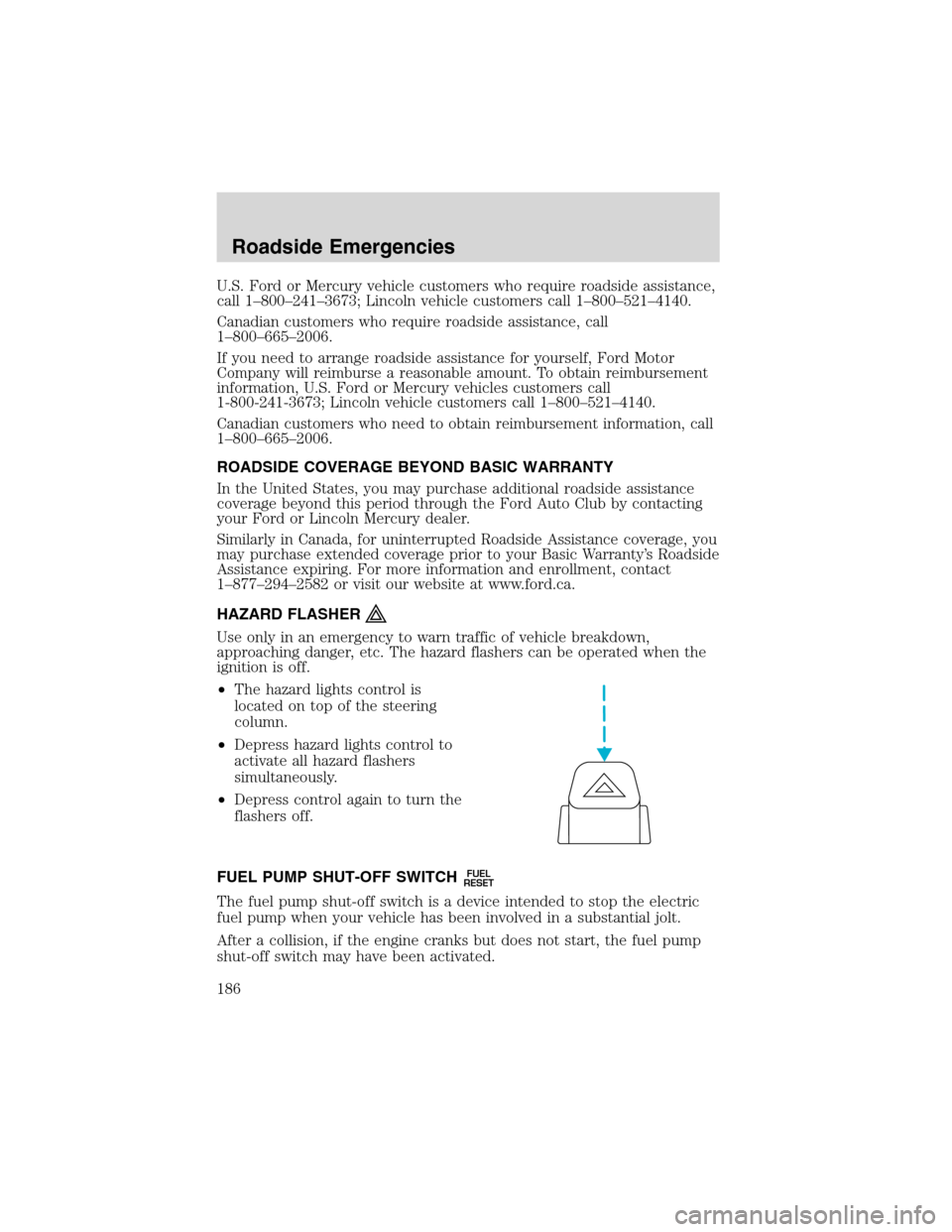
•The hazard lights control is
located on top of the steering
column.
•Depress hazard lights control to
activate all hazard flashers
simultaneously.
•Depress control again to turn the
flashers off.
FUEL PUMP SHUT-OFF SWITCH
FUEL
RESET
The fuel pump shut-off switch is a device intended to stop the electric
fuel pump when your vehicle has been involved in a substantial jolt.
After a collision, if the engine cranks but does not start, the fuel pump
shut-off switch may have been activated.
Roadside Emergencies
186
Page 190 of 272
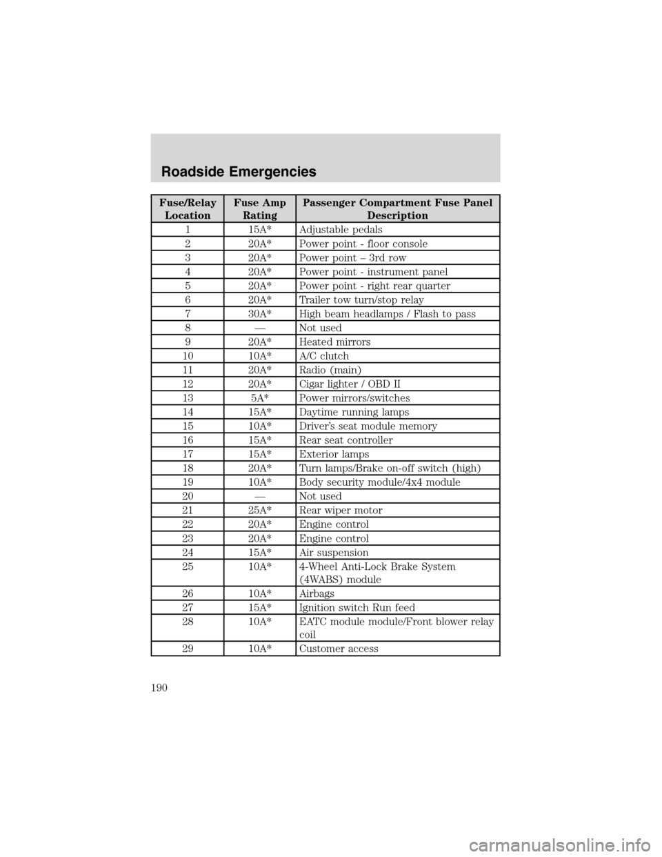
Fuse/Relay
LocationFuse Amp
RatingPassenger Compartment Fuse Panel
Description
1 15A* Adjustable pedals
2 20A* Power point - floor console
3 20A* Power point – 3rd row
4 20A* Power point - instrument panel
5 20A* Power point - right rear quarter
6 20A* Trailer tow turn/stop relay
7 30A* High beam headlamps / Flash to pass
8 — Not used
9 20A* Heated mirrors
10 10A* A/C clutch
11 20A* Radio (main)
12 20A* Cigar lighter / OBD II
13 5A* Power mirrors/switches
14 15A* Daytime running lamps
15 10A* Driver’s seat module memory
16 15A* Rear seat controller
17 15A* Exterior lamps
18 20A* Turn lamps/Brake on-off switch (high)
19 10A* Body security module/4x4 module
20 — Not used
21 25A* Rear wiper motor
22 20A* Engine control
23 20A* Engine control
24 15A* Air suspension
25 10A* 4-Wheel Anti-Lock Brake System
(4WABS) module
26 10A* Airbags
27 15A* Ignition switch Run feed
28 10A* EATC module module/Front blower relay
coil
29 10A* Customer access
Roadside Emergencies
190
Page 193 of 272
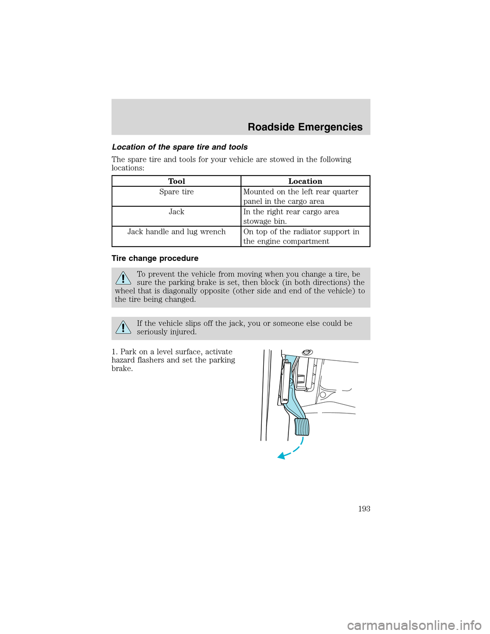
Location of the spare tire and tools
The spare tire and tools for your vehicle are stowed in the following
locations:
Tool Location
Spare tire Mounted on the left rear quarter
panel in the cargo area
Jack In the right rear cargo area
stowage bin.
Jack handle and lug wrench On top of the radiator support in
the engine compartment
Tire change procedure
To prevent the vehicle from moving when you change a tire, be
sure the parking brake is set, then block (in both directions) the
wheel that is diagonally opposite (other side and end of the vehicle) to
the tire being changed.
If the vehicle slips off the jack, you or someone else could be
seriously injured.
1. Park on a level surface, activate
hazard flashers and set the parking
brake.
Roadside Emergencies
193
Page 194 of 272
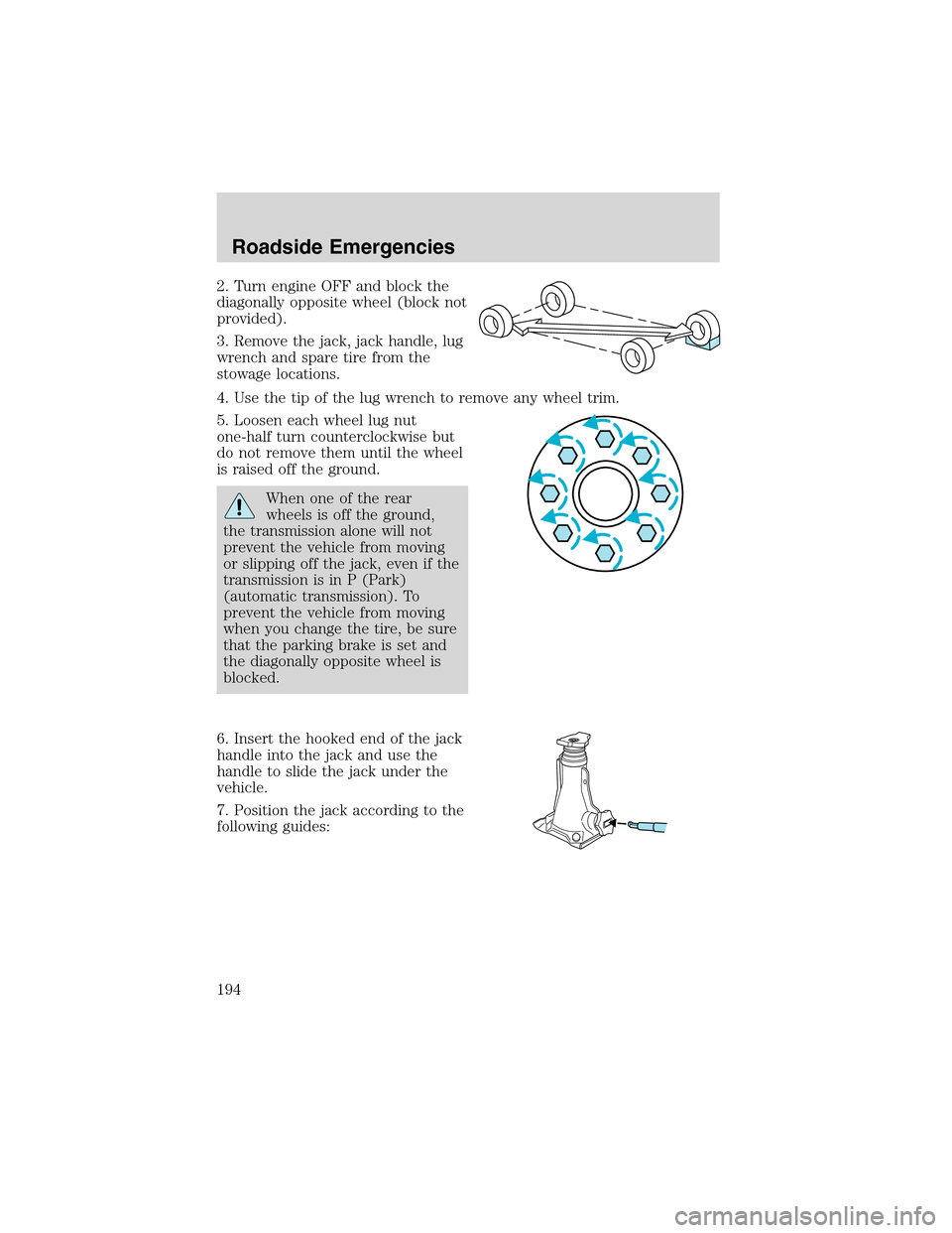
2. Turn engine OFF and block the
diagonally opposite wheel (block not
provided).
3. Remove the jack, jack handle, lug
wrench and spare tire from the
stowage locations.
4. Use the tip of the lug wrench to remove any wheel trim.
5. Loosen each wheel lug nut
one-half turn counterclockwise but
do not remove them until the wheel
is raised off the ground.
When one of the rear
wheels is off the ground,
the transmission alone will not
prevent the vehicle from moving
or slipping off the jack, even if the
transmission is in P (Park)
(automatic transmission). To
prevent the vehicle from moving
when you change the tire, be sure
that the parking brake is set and
the diagonally opposite wheel is
blocked.
6. Insert the hooked end of the jack
handle into the jack and use the
handle to slide the jack under the
vehicle.
7. Position the jack according to the
following guides:
Roadside Emergencies
194
Page 196 of 272
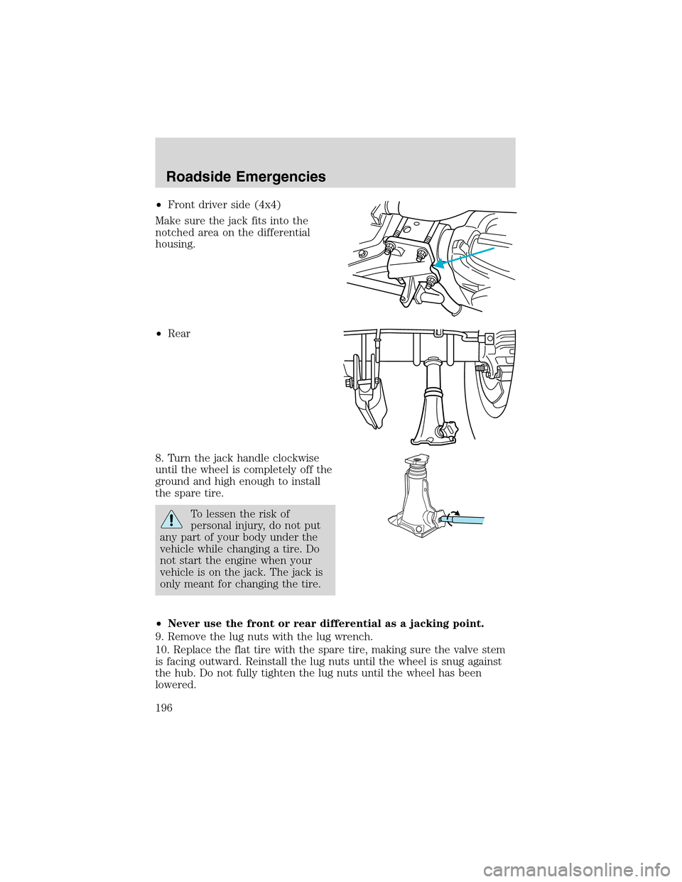
•Front driver side (4x4)
Make sure the jack fits into the
notched area on the differential
housing.
•Rear
8. Turn the jack handle clockwise
until the wheel is completely off the
ground and high enough to install
the spare tire.
To lessen the risk of
personal injury, do not put
any part of your body under the
vehicle while changing a tire. Do
not start the engine when your
vehicle is on the jack. The jack is
only meant for changing the tire.
•Never use the front or rear differential as a jacking point.
9. Remove the lug nuts with the lug wrench.
10. Replace the flat tire with the spare tire, making sure the valve stem
is facing outward. Reinstall the lug nuts until the wheel is snug against
the hub. Do not fully tighten the lug nuts until the wheel has been
lowered.
Roadside Emergencies
196
Page 198 of 272
1.Use only a 12–volt supply to start your vehicle.
2. Do not disconnect the battery of the disabled vehicle as this could
damage the vehicle’s electrical system.
3. Park the booster vehicle close to the hood of the disabled vehicle
making sure the two vehiclesdo nottouch. Set the parking brake on
both vehicles and stay clear of the engine cooling fan and other moving
parts.
4. Check all battery terminals and remove any excessive corrosion before
you attach the battery cables. Ensure that vent caps are tight and level.
5. Turn the heater fan on in both vehicles to protect any electrical
surges. Turn all other accessories off.
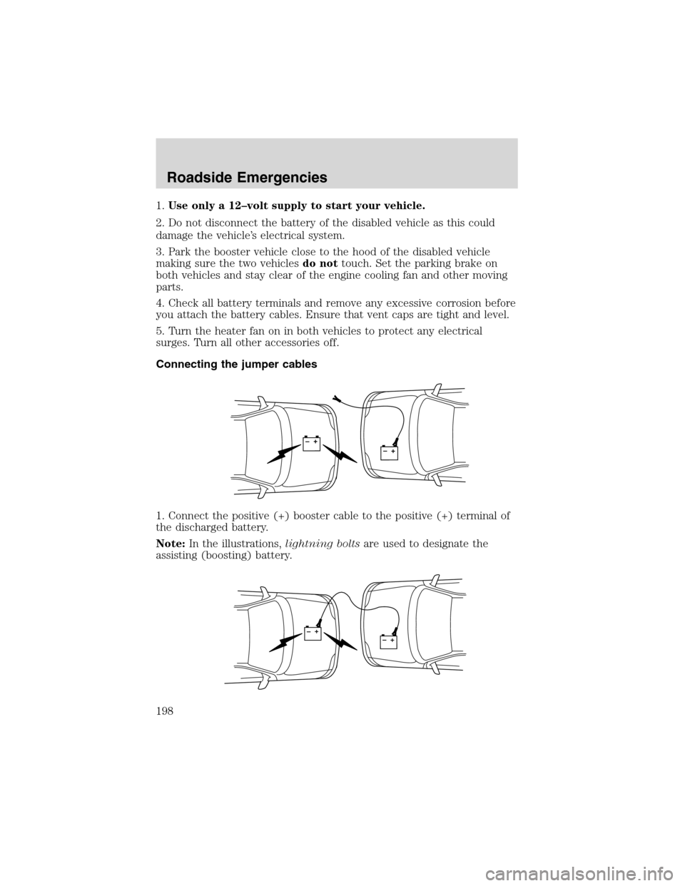
Connecting the jumper cables
1. Connect the positive (+) booster cable to the positive (+) terminal of
the discharged battery.
Note:In the illustrations,lightning boltsare used to designate the
assisting (boosting) battery.
+–+–
+–+–
Roadside Emergencies
198
Page 199 of 272
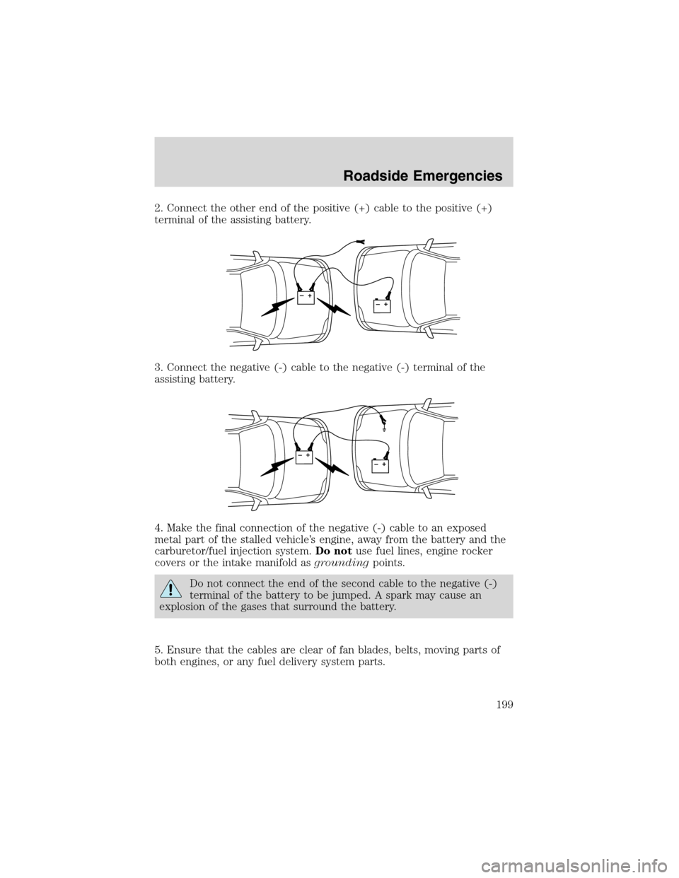
2. Connect the other end of the positive (+) cable to the positive (+)
terminal of the assisting battery.
3. Connect the negative (-) cable to the negative (-) terminal of the
assisting battery.
4. Make the final connection of the negative (-) cable to an exposed
metal part of the stalled vehicle’s engine, away from the battery and the
carburetor/fuel injection system.Do notuse fuel lines, engine rocker
covers or the intake manifold asgroundingpoints.
Do not connect the end of the second cable to the negative (-)
terminal of the battery to be jumped. A spark may cause an
explosion of the gases that surround the battery.
5. Ensure that the cables are clear of fan blades, belts, moving parts of
both engines, or any fuel delivery system parts.
+–+–
+–+–
Roadside Emergencies
199