wiring FORD EXPEDITION 1997 1.G Owners Manual
[x] Cancel search | Manufacturer: FORD, Model Year: 1997, Model line: EXPEDITION, Model: FORD EXPEDITION 1997 1.GPages: 224, PDF Size: 2.2 MB
Page 89 of 224

If the air bag is inflated,
the air bag will not
function again and must be
replaced immediately.Ifthe
air bag is not replaced, the
unrepaired area will increase the
risk of injury in a collision.
The SRS consists of:
²driver and passenger air bag
modules (which include the
inflators and air bags),
²one or more impact and safing
sensors,
²a readiness light and tone
²and the electrical wiring which
connects the components.
The diagnostic module monitors its
own internal circuits and the
supplemental air bag electrical
system readiness (including the
impact sensors), the system wiring,
the air bag system readiness light,
the air bag back up power and the
air bag ignitors.
Determining if the system is
operational
The SRS uses a readiness light in
the instrument cluster or a tone to
indicate the condition of the
system. Refer to theAir bag
readinesssection in the
Instrumentationchapter. Routine
maintenance of the air bag is not
required.
exd_determing_operational
Seating and safety restraints
90
Page 130 of 224

vehicle frame or hook retainers
(not the bumper). Make sure there
is enough slack to allow the vehicle
to turn corners.
For more information, refer to
ªFord Recreational Vehicle and
Trailer Towing Guideº available
from your Ford dealer.
Using trailer lamps
See your local trailer retailer or
rental agency for proper
instructions and equipment for
hooking up trailer lamps.
Do not hook the trailer lights
directly into the vehicle's wiring
system. If the trailer lamps are not
connected properly, the warning
lights in the instrument cluster
may not work properly.
Using a hitch
Do not use hitches that:
²clamp onto the vehicle bumper
²attach to the axle.
Distribute the load so that only 10
to 15% of the total weight of the
trailer is on the tongue. Tie down
the load so that it does not shift
and change the weight on the
hitch. Follow the towing
instructions of a reputable rental
agency.
Using a load-equalizing hitch
Follow the hitch manufactures
guidelines for the installation and
specific use of a load equalizing
hitch on this vehicle. In no cases
exd_lamps_trailer
exd_hitch_using
exd_load_equalizing_hitch
Driving
131
Page 187 of 224

²Install cables securely, verifying
that the cables do not touch any
wiring, brake lines or fuel lines.
²Drive cautiously. If you hear the
cables rub or bang against the
vehicle, stop and retighten
them. If this does not work,
remove the cables to prevent
vehicle damage.
²Avoid overloading your vehicle.
²Remove the tire cables when
they are no longer needed.
²Do not use cables on dry roads.
²The suspension insulation and
bumpers will help prevent
vehicle damage. Do not remove
these components from the
vehicle when using snow tires
and traction devices.
²Do not exceed 48 km/h (30
mph) with tire cables on your
vehicle.
Consult your dealer for information
on other Ford approved methods
of traction control.
FUEL INFORMATION
The ignition key must be turned to
3 (Off) or 1 (Acc) during refueling
to obtain accurate fuel gauge
ratings.
exd_fuel_info
exd_important_precautions
Maintenance and care
188
Page 199 of 224

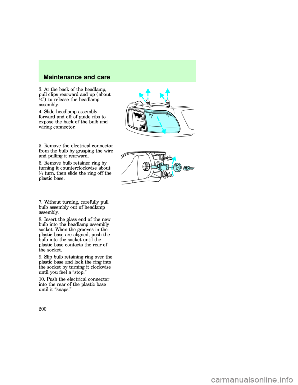
3. At the back of the headlamp,
pull clips rearward and up (about
ôº) to release the headlamp
assembly.
4. Slide headlamp assembly
forward and off of guide ribs to
expose the back of the bulb and
wiring connector.
5. Remove the electrical connector
from the bulb by grasping the wire
and pulling it rearward.
6. Remove bulb retainer ring by
turning it counterclockwise about
1¤4turn, then slide the ring off the
plastic base.
7. Without turning, carefully pull
bulb assembly out of headlamp
assembly.
8. Insert the glass end of the new
bulb into the headlamp assembly
socket. When the grooves in the
plastic base are aligned, push the
bulb into the socket until the
plastic base contacts the rear of
the socket.
9. Slip bulb retaining ring over the
plastic base and lock the ring into
the socket by turning it clockwise
until you feel a ªstop.º
10. Push the electrical connector
into the rear of the plastic base
until it ªsnaps.º
Maintenance and care
200