maintenance FORD EXPEDITION 1998 1.G Owners Manual
[x] Cancel search | Manufacturer: FORD, Model Year: 1998, Model line: EXPEDITION, Model: FORD EXPEDITION 1998 1.GPages: 216, PDF Size: 1.51 MB
Page 1 of 216
Before driving
Introduction 2
Instrumentation 4
Controls and features 20
Seating and safety restraints 60
Starting and driving
Starting 92
Driving 98
Roadside emergencies 127
Servicing
Maintenance and care 150
Capacities and specifications 200
Reporting safety defects 207
Index 208
All rights reserved. Reproduction by any means, electronic or mechanical
including photocopying, recording or by any information storage
and retrieval system or translation in whole or part is not permitted without
written authorization from Ford Motor Company.
Copyright
r1997 Ford Motor Company
Elemental Chlorine Free
Contents
1
Page 9 of 216

Brake system warning
Momentarily illuminates when the
ignition is turned on and the
engine is off. Also illuminates when
the parking brake is engaged.
Illumination after releasing the
parking brake indicates low brake
fluid level.
Anti-lock brake system (ABS)
Momentarily illuminates when the
ignition is turned on and the
engine is off. If the light remains
on, continues to flash or fails to
illuminate, have the system
serviced immediately.
Turn signal
Illuminates when the left or right
turn signal or the hazard lights are
turned on. If one or both of the
indicators stay on continuously or
flash faster, check for a burned-out
turn signal bulb. Refer toExterior
bulbsin theMaintenance and
carechapter.
High beams
Illuminates when the high beam
headlamps are turned on.
!
BRAKE
ABS
Instrumentation
9
Page 14 of 216
than the advertised capacity due to
the reserve fuel.
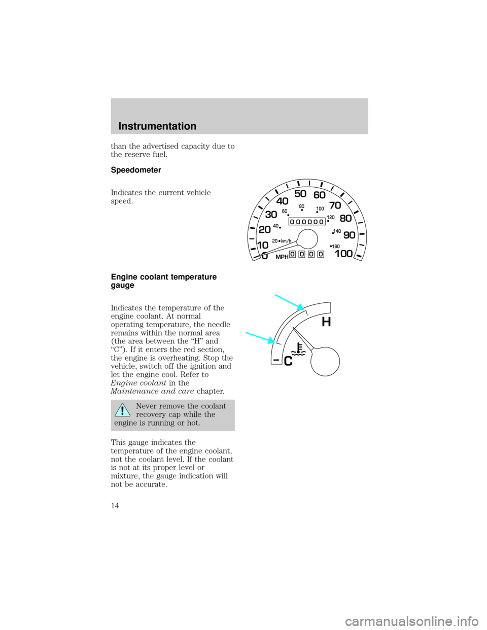
Speedometer
Indicates the current vehicle
speed.
Engine coolant temperature
gauge
Indicates the temperature of the
engine coolant. At normal
operating temperature, the needle
remains within the normal area
(the area between the ªHº and
ªCº). If it enters the red section,
the engine is overheating. Stop the
vehicle, switch off the ignition and
let the engine cool. Refer to
Engine coolantin the
Maintenance and carechapter.
Never remove the coolant
recovery cap while the
engine is running or hot.
This gauge indicates the
temperature of the engine coolant,
not the coolant level. If the coolant
is not at its proper level or
mixture, the gauge indication will
not be accurate.
0
000000000
MPH
20km/h 406080
100
120
140
160
0 1020304050
60
70
80
90
100
H
C
Instrumentation
14
Page 16 of 216
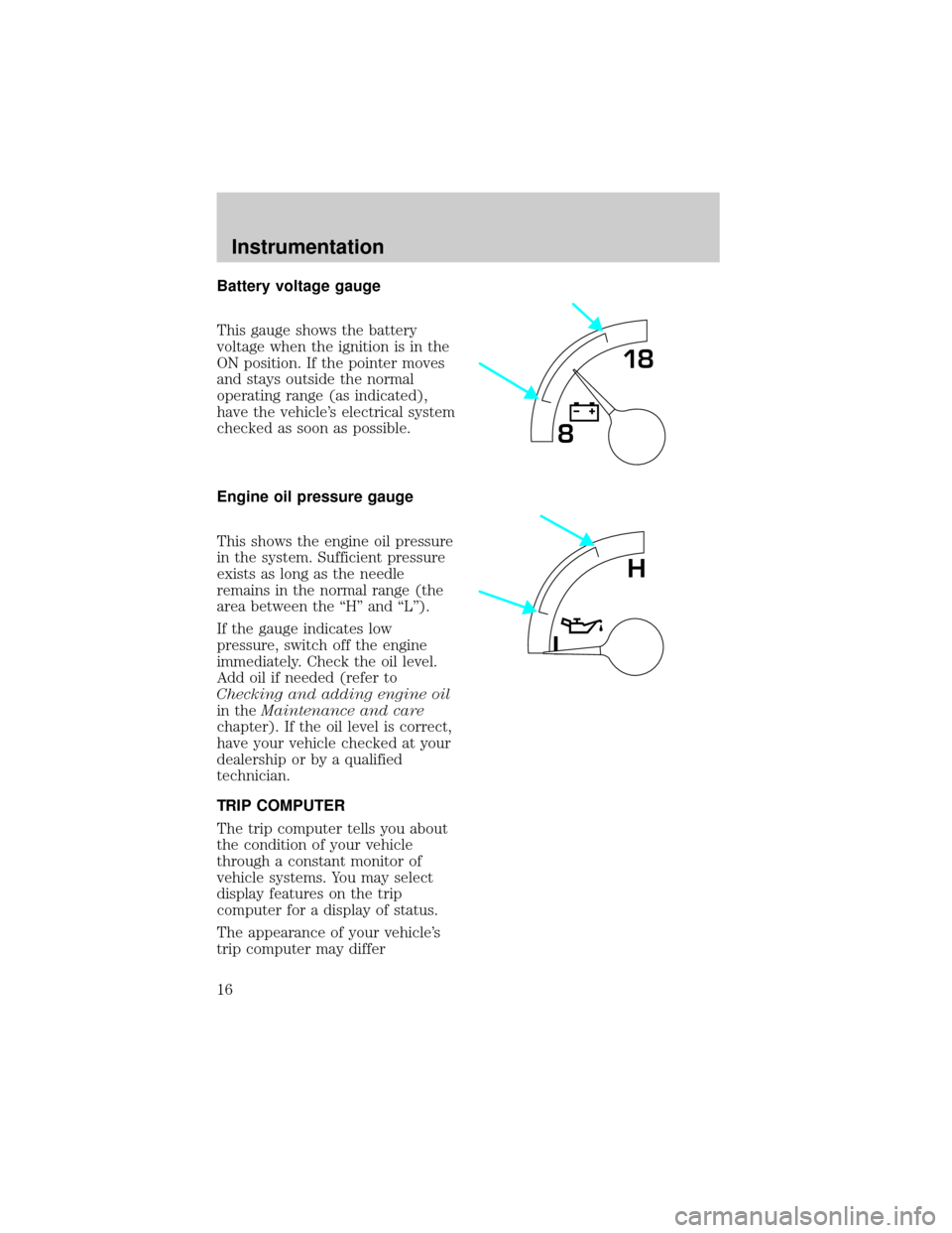
Battery voltage gauge
This gauge shows the battery
voltage when the ignition is in the
ON position. If the pointer moves
and stays outside the normal
operating range (as indicated),
have the vehicle's electrical system
checked as soon as possible.
Engine oil pressure gauge
This shows the engine oil pressure
in the system. Sufficient pressure
exists as long as the needle
remains in the normal range (the
area between the ªHº and ªLº).
If the gauge indicates low
pressure, switch off the engine
immediately. Check the oil level.
Add oil if needed (refer to
Checking and adding engine oil
in theMaintenance and care
chapter). If the oil level is correct,
have your vehicle checked at your
dealership or by a qualified
technician.
TRIP COMPUTER
The trip computer tells you about
the condition of your vehicle
through a constant monitor of
vehicle systems. You may select
display features on the trip
computer for a display of status.
The appearance of your vehicle's
trip computer may differ
818
L
H
Instrumentation
16
Page 77 of 216
Conditions of operation
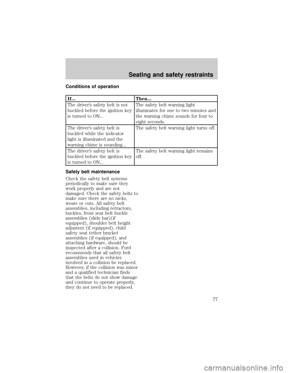
If... Then...
The driver's safety belt is not
buckled before the ignition key
is turned to ON...The safety belt warning light
illuminates for one to two minutes and
the warning chime sounds for four to
eight seconds.
The driver's safety belt is
buckled while the indicator
light is illuminated and the
warning chime is sounding...The safety belt warning light turns off.
The driver's safety belt is
buckled before the ignition key
is turned to ON...The safety belt warning light remains
off.
Safety belt maintenance
Check the safety belt systems
periodically to make sure they
work properly and are not
damaged. Check the safety belts to
make sure there are no nicks,
wears or cuts. All safety belt
assemblies, including retractors,
buckles, front seat belt buckle
assemblies (slide bar)(if
equipped), shoulder belt height
adjusters (if equipped), child
safety seat tether bracket
assemblies (if equipped), and
attaching hardware, should be
inspected after a collision. Ford
recommends that all safety belt
assemblies used in vehicles
involved in a collision be replaced.
However, if the collision was minor
and a qualified technician finds
that the belts do not show damage
and continue to operate properly,
they do not need to be replaced.
Seating and safety restraints
77
Page 78 of 216
Safety belt assemblies not in use
during a collision should also be
inspected and replaced if either
damage or improper operation is
noted.
Failure to replace the
safety belt assembly under
the above conditions could result
in severe personal injuries in the
event of a collision.
Refer toCleaning and
maintaining the safety beltsin
theMaintenance and care
section.
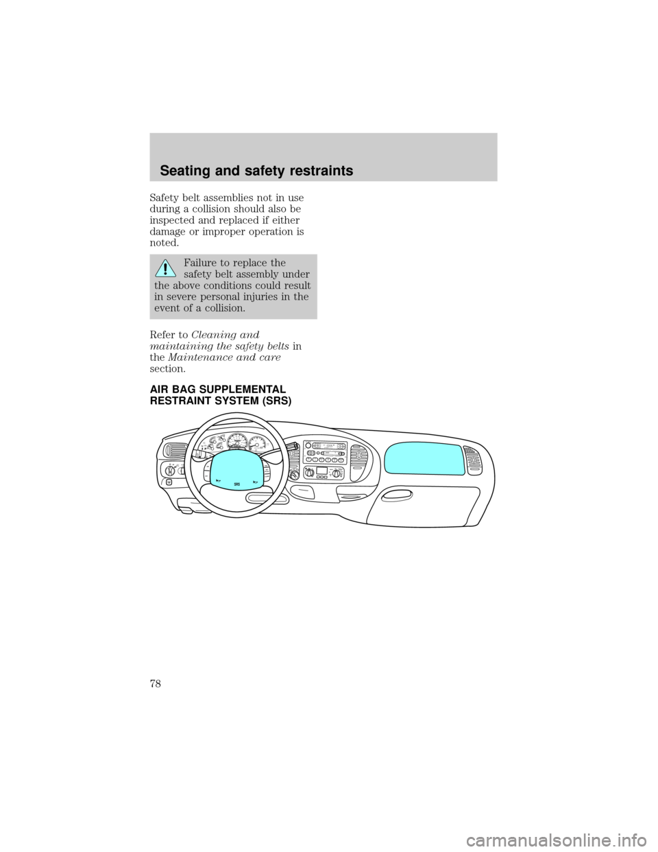
AIR BAG SUPPLEMENTAL
RESTRAINT SYSTEM (SRS)
FOR
SCANEJ
REWFF SIDE 1-2COMPSHUFFLETAPECDDISCSBASS
TREB
BAL
FADEAUTO
SETVOL - PUSH ONS
E
E
KTUNEAM
FM
12 3456fwDOLBY B NRFM1S
TDOOR
AJAR
BRAKEF
E
H H
18
820
10304050
60
70
80
90
10020 406080
100
120
140
160
MPH km/h00000000
012PRN 21RPMx1000CHECK
ENGINE THEFT3
4
5
6CHECK
SUSPLOW
FUEL
ABS
PPULL
FOGPANEL
DIM4H
A4WD4LFLOOR
PANELLO
HICOOLW
ARMDEF FLR&
DEF PANEL &
FLOOR OFFPAN
ELLO
HIFLR&
DEF PAN
EL &
FLOOR OFF
M
AX
AC AC FLOORFAN
OVERDRIVE
SRS
ON
OFFRES
SET
ACCELCOAST
Seating and safety restraints
78
Page 82 of 216
If the air bag is inflated,
the air bag will not
function again and must be
replaced immediately.Ifthe
air bag is not replaced, the
unrepaired area will increase the
risk of injury in a collision.
The SRS consists of:
²driver and passenger air bag
modules (which include the
inflators and air bags),
²one or more impact and safing
sensors,
²a readiness light and tone
²and the electrical wiring which
connects the components.
The diagnostic module monitors its
own internal circuits and the
supplemental air bag electrical
system warning (including the
impact sensors), the system wiring,
the air bag system readiness light,
the air bag back up power and the
air bag ignitors.
Determining if the system is
operational
The SRS uses a readiness light in
the instrument cluster or a tone to
indicate the condition of the
system. Refer to theAir bag
readinesssection in the
Instrumentationchapter. Routine
maintenance of the air bag is not
required.
Seating and safety restraints
82
Page 98 of 216

BRAKES
Your brakes are self-adjusting.
Refer to the ªService Guideº for
scheduled maintenance.
Occasional brake noise is normal
and often does not indicate a
performance concern with the
vehicle's brake system. In normal
operation, automotive brake
systems may emit occasional or
intermittent squeal or groan noises
when the brakes are applied. Such
noises are usually heard during the
first few brake applications in the
morning; however, they may be
heard at any time while braking
and can be aggravated by
environmental conditions such as
cold, heat, moisture, road dust, salt
or mud. If a ªmetal-to-metal,º
ªcontinuous grindingº or
ªcontinuous squealº sound is
present while braking, the brake
linings may be worn-out and
should be inspected by a qualified
service technician.
Anti-lock brake system (ABS)
On vehicles equipped with an
anti-lock braking system (ABS), a
noise from the hydraulic pump
motor and pulsation in the pedal
may be observed during ABS
braking events. Pedal pulsation
coupled with noise while braking
under panic conditions or on loose
gravel, bumps, wet or snowy roads
is normal and indicates proper
functioning of the vehicle's
anti-lock brake system. If the
vehicle has continuous vibration or
Driving
98
Page 126 of 216
LUGGAGE RACK
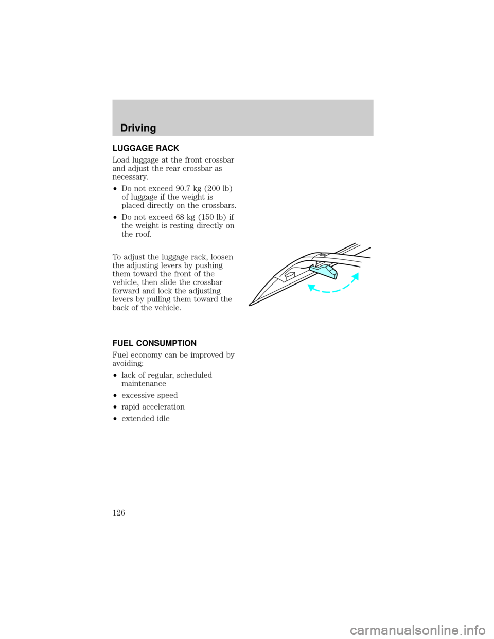
Load luggage at the front crossbar
and adjust the rear crossbar as
necessary.
²Do not exceed 90.7 kg (200 lb)
of luggage if the weight is
placed directly on the crossbars.
²Do not exceed 68 kg (150 lb) if
the weight is resting directly on
the roof.
To adjust the luggage rack, loosen
the adjusting levers by pushing
them toward the front of the
vehicle, then slide the crossbar
forward and lock the adjusting
levers by pulling them toward the
back of the vehicle.
FUEL CONSUMPTION
Fuel economy can be improved by
avoiding:
²lack of regular, scheduled
maintenance
²excessive speed
²rapid acceleration
²extended idle
Driving
126
Page 150 of 216

SERVICE RECOMMENDATIONS
To help you service your vehicle:
²We highlight do-it-yourself items
in the engine compartment for
easy location.
²We provide a ªService Guideº
which makes tracking routine
service easy.
If your vehicle requires
professional service, your
dealership can provide necessary
parts and service. Check your
ªWarranty Guideº to find out which
parts and services are covered.
Use only recommended fuels,
lubricants, fluids and service parts
conforming to specifications.
Motorcraft parts are designed and
built to provide the best
performance in your vehicle.
PRECAUTIONS WHEN
SERVICING YOUR VEHICLE
Be especially careful when
inspecting or servicing your
vehicle.
²Do not work on a hot engine.
²When the engine is running,
make sure that loose clothing,
jewelry or long hair does not get
caught up in moving parts.
²Do not work on a vehicle with
the engine running in an
enclosed space, unless you are
sure you have enough
ventilation.
Maintenance and care
150