fuse FORD EXPEDITION 2002 1.G Owners Manual
[x] Cancel search | Manufacturer: FORD, Model Year: 2002, Model line: EXPEDITION, Model: FORD EXPEDITION 2002 1.GPages: 280, PDF Size: 2.32 MB
Page 2 of 280
Seating and safety restraints 108
Seating 108
Safety restraints 120
Air bags 132
Child restraints 140
Driving 150
Starting 150
Brakes 154
Transmission operation 161
Vehicle loading 177
Trailer towing 180
Recreational towing 185
Roadside emergencies 186
Hazard flasher switch 187
Fuses and relays 189
Changing tires 196
Jump starting 202
Wrecker towing 207
Customer assistance 208
The dispute settlement board 211
Utilizing the mediation/arbitration 214
Getting assistance outside the U.S. and Canada 214
Ordering additional owner's literature 215
Reporting safety defects (U.S. only) 217
Cleaning 218
Cleaning your vehicle 218
Underbody preservation 223
Table of contents
2
Page 8 of 280
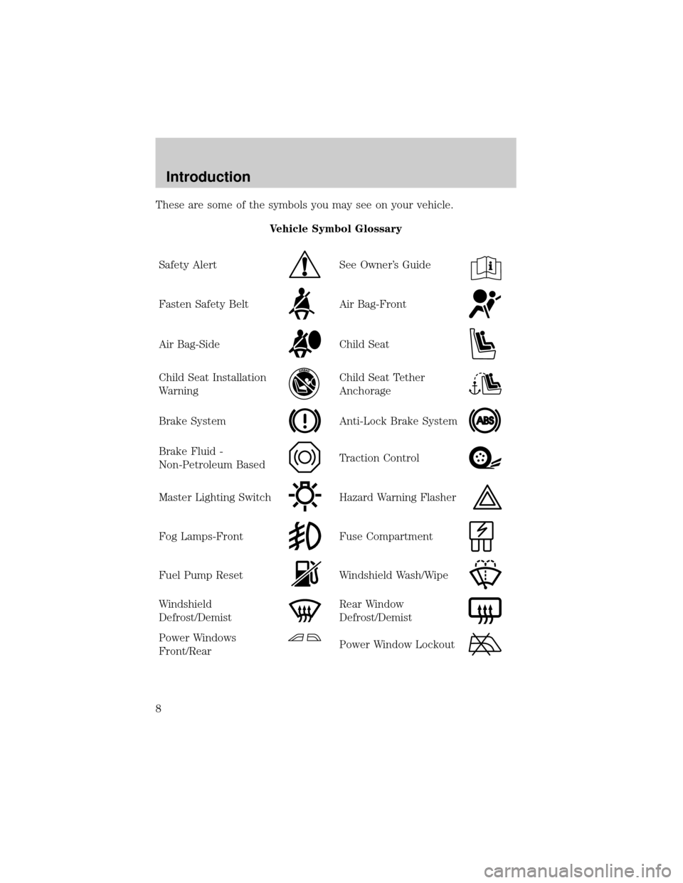
These are some of the symbols you may see on your vehicle.
Vehicle Symbol Glossary
Safety Alert
See Owner's Guide
Fasten Safety BeltAir Bag-Front
Air Bag-SideChild Seat
Child Seat Installation
WarningChild Seat Tether
Anchorage
Brake SystemAnti-Lock Brake System
Brake Fluid -
Non-Petroleum BasedTraction Control
Master Lighting SwitchHazard Warning Flasher
Fog Lamps-FrontFuse Compartment
Fuel Pump ResetWindshield Wash/Wipe
Windshield
Defrost/DemistRear Window
Defrost/Demist
Power Windows
Front/RearPower Window Lockout
Introduction
8
Page 134 of 280
Do not put anything on or over the air bag module. Placing
objects on or over the air bag inflation area may cause those
objects to be propelled by the air bag into your face and torso causing
serious injury.
Do not attempt to service, repair, or modify the air bag
supplemental restraint systems or its fuses. See your Ford or
Lincoln Mercury dealer.
The front passenger air bag is not designed to offer protection to
occupants in the center front seating position.
Modifications to the front end of the vehicle, including frame,
bumper, front end body structure and tow hooks may affect the
performance of the air bag sensors increasing the risk of injury. Do not
modify the front end of the vehicle.
Additional equipment may affect the performance of the air bag
sensors increasing the risk of injury. Please refer to the Body
Builders Layout Book for instructions about the appropriate installation
of additional equipment.
Seating and safety restraints
134
Page 138 of 280
Do not attempt to service, repair, or modify the air bag
supplemental restraint system, its fuses or the seat cover on a
seat containing an air bag. See your Ford or Lincoln Mercury dealer.
All occupants of the vehicle including the driver should always
wear their safety belts even when an air bag SRS is provided.
How does the side air bag system work?
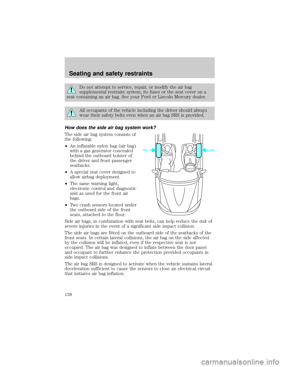
The side air bag system consists of
the following:
²An inflatable nylon bag (air bag)
with a gas generator concealed
behind the outboard bolster of
the driver and front passenger
seatbacks.
²A special seat cover designed to
allow airbag deployment.
²The same warning light,
electronic control and diagnostic
unit as used for the front air
bags.
²Two crash sensors located under
the outboard side of the front
seats, attached to the floor.
Side air bags, in combination with seat belts, can help reduce the risk of
severe injuries in the event of a significant side impact collision.
The side air bags are fitted on the outboard side of the seatbacks of the
front seats. In certain lateral collisions, the air bag on the side affected
by the collision will be inflated, even if the respective seat is not
occupied. The air bag was designed to inflate between the door panel
and occupant to further enhance the protection provided occupants in
side impact collisions.
The air bag SRS is designed to activate when the vehicle sustains lateral
deceleration sufficient to cause the sensors to close an electrical circuit
that initiates air bag inflation.
Seating and safety restraints
138
Page 161 of 280
AUTOMATIC TRANSMISSION OPERATION
Brake-shift interlock
This vehicle is equipped with a brake-shift interlock feature that prevents
the gearshift lever from being moved from P (Park) when the ignition is
in the ON position unless brake pedal is depressed.
If you cannot move the gearshift lever out of P (Park) with ignition in
the ON position and the brake pedal depressed:
1. Apply the parking brake, turn ignition key to LOCK, then remove the
key.
2. Insert the key and turn it to OFF.Apply the brake pedal and shift
to N (Neutral).
3. Start the vehicle.
If it is necessary to use the above procedure to move the gearshift lever,
it is possible that a fuse has blown or the vehicle's brakelamps are not
operating properly. Refer toFuses and relaysin theRoadside
emergencieschapter.
Do not drive your vehicle until you verify that the brakelamps
are working.
If your vehicle gets stuck in mud or snow it may be rocked out by
shifting from forward and reverse gears, stopping between shifts, in a
steady pattern. Press lightly on the accelerator in each gear.
Do not rock the vehicle if the engine is not at normal operating
temperature or damage to the transmission may occur.
Do not rock the vehicle for more than a few minutes or damage
to the transmission and tires may occur or the engine may
overheat.
Always set the parking brake fully and make sure the gearshift is
latched in P (Park). Turn off the ignition whenever you leave
your vehicle.
If the parking brake is fully released, but the brake warning lamp
remains illuminated, the brakes may not be working properly.
See your dealer or a qualified service technician.
Driving
161
Page 189 of 280
FUSES AND RELAYS
Fuses
If electrical components in the
vehicle are not working, a fuse may
have blown. Blown fuses are
identified by a broken wire within
the fuse. Check the appropriate
fuses before replacing any electrical
components.
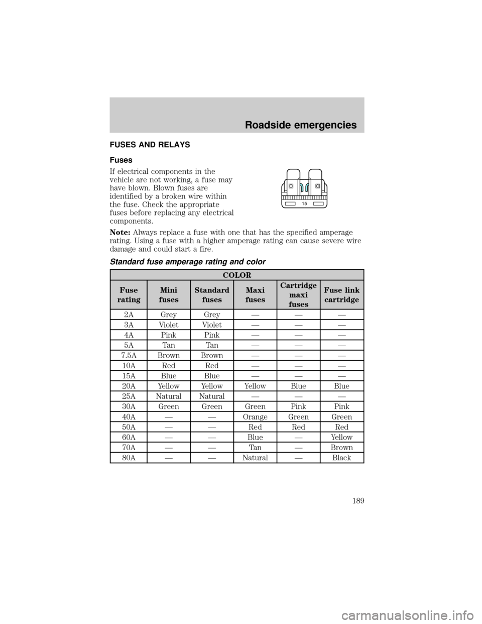
Note:Always replace a fuse with one that has the specified amperage
rating. Using a fuse with a higher amperage rating can cause severe wire
damage and could start a fire.
Standard fuse amperage rating and color
COLOR
Fuse
ratingMini
fusesStandard
fusesMaxi
fusesCartridge
maxi
fusesFuse link
cartridge
2A Grey Grey Ð Ð Ð
3A Violet Violet Ð Ð Ð
4A Pink Pink Ð Ð Ð
5A Tan Tan Ð Ð Ð
7.5A Brown Brown Ð Ð Ð
10A Red Red Ð Ð Ð
15A Blue Blue Ð Ð Ð
20A Yellow Yellow Yellow Blue Blue
25A Natural Natural Ð Ð Ð
30A Green Green Green Pink Pink
40A Ð Ð Orange Green Green
50A Ð Ð Red Red Red
60A Ð Ð Blue Ð Yellow
70A Ð Ð Tan Ð Brown
80A Ð Ð Natural Ð Black
15
Roadside emergencies
189
Page 190 of 280
Passenger compartment fuse panel
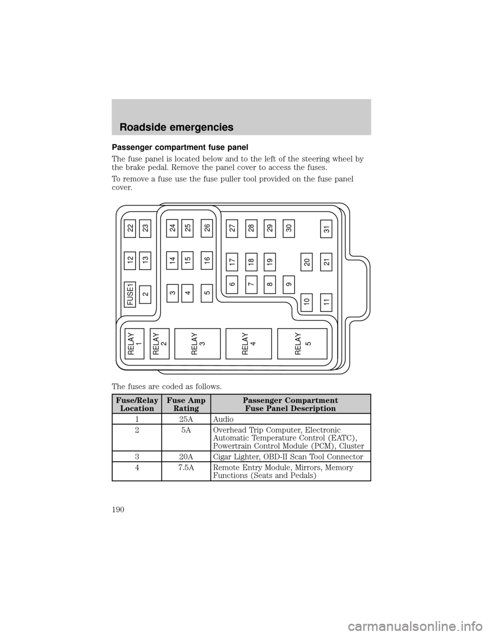
The fuse panel is located below and to the left of the steering wheel by
the brake pedal. Remove the panel cover to access the fuses.
To remove a fuse use the fuse puller tool provided on the fuse panel
cover.
The fuses are coded as follows.
Fuse/Relay
LocationFuse Amp
RatingPassenger Compartment
Fuse Panel Description
1 25A Audio
2 5A Overhead Trip Computer, Electronic
Automatic Temperature Control (EATC),
Powertrain Control Module (PCM), Cluster
3 20A Cigar Lighter, OBD-II Scan Tool Connector
4 7.5A Remote Entry Module, Mirrors, Memory
Functions (Seats and Pedals)
FUSE1 12 22
21323
617 27
718 28
819 29
930
20
31 21 11 10
RELAY
5 RELAY
4 RELAY
3 RELAY
2 RELAY
1
31424
41525
51626
Roadside emergencies
190
Page 191 of 280
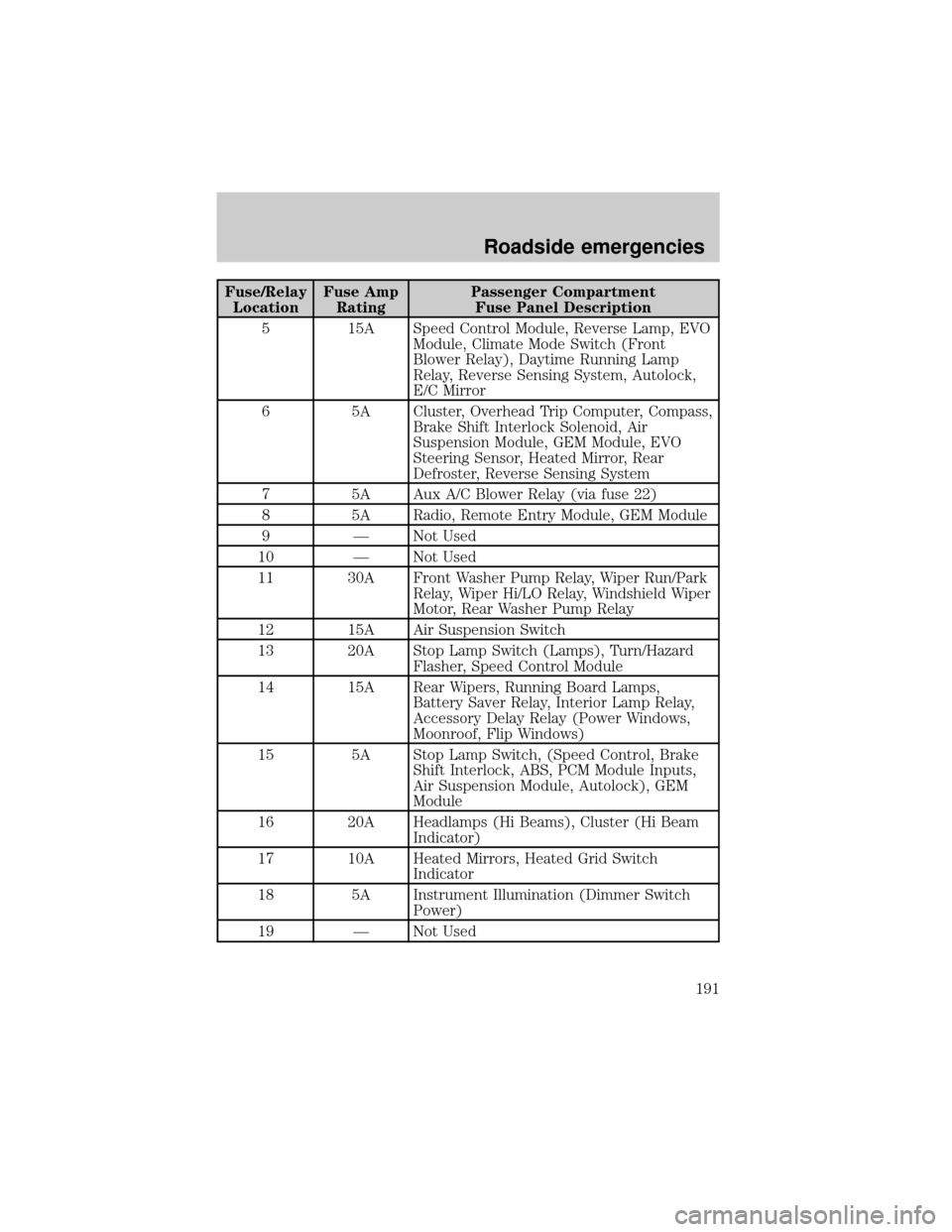
Fuse/Relay
LocationFuse Amp
RatingPassenger Compartment
Fuse Panel Description
5 15A Speed Control Module, Reverse Lamp, EVO
Module, Climate Mode Switch (Front
Blower Relay), Daytime Running Lamp
Relay, Reverse Sensing System, Autolock,
E/C Mirror
6 5A Cluster, Overhead Trip Computer, Compass,
Brake Shift Interlock Solenoid, Air
Suspension Module, GEM Module, EVO
Steering Sensor, Heated Mirror, Rear
Defroster, Reverse Sensing System
7 5A Aux A/C Blower Relay (via fuse 22)
8 5A Radio, Remote Entry Module, GEM Module
9 Ð Not Used
10 Ð Not Used
11 30A Front Washer Pump Relay, Wiper Run/Park
Relay, Wiper Hi/LO Relay, Windshield Wiper
Motor, Rear Washer Pump Relay
12 15A Air Suspension Switch
13 20A Stop Lamp Switch (Lamps), Turn/Hazard
Flasher, Speed Control Module
14 15A Rear Wipers, Running Board Lamps,
Battery Saver Relay, Interior Lamp Relay,
Accessory Delay Relay (Power Windows,
Moonroof, Flip Windows)
15 5A Stop Lamp Switch, (Speed Control, Brake
Shift Interlock, ABS, PCM Module Inputs,
Air Suspension Module, Autolock), GEM
Module
16 20A Headlamps (Hi Beams), Cluster (Hi Beam
Indicator)
17 10A Heated Mirrors, Heated Grid Switch
Indicator
18 5A Instrument Illumination (Dimmer Switch
Power)
19 Ð Not Used
Roadside emergencies
191
Page 192 of 280
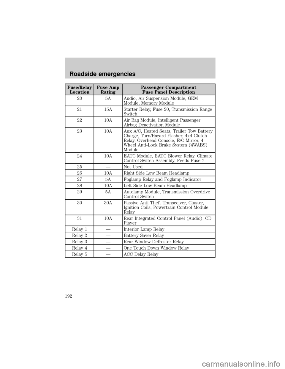
Fuse/Relay
LocationFuse Amp
RatingPassenger Compartment
Fuse Panel Description
20 5A Audio, Air Suspension Module, GEM
Module, Memory Module
21 15A Starter Relay, Fuse 20, Transmission Range
Switch
22 10A Air Bag Module, Intelligent Passenger
Airbag Deactivation Module
23 10A Aux A/C, Heated Seats, Trailer Tow Battery
Charge, Turn/Hazard Flasher, 4x4 Clutch
Relay, Overhead Console, E/C Mirror, 4
Wheel Anti-Lock Brake System (4WABS)
Module
24 10A EATC Module, EATC Blower Relay, Climate
Control Switch Assembly, Feeds Fuse 7
25 Ð Not Used
26 10A Right Side Low Beam Headlamp
27 5A Foglamp Relay and Foglamp Indicator
28 10A Left Side Low Beam Headlamp
29 5A Autolamp Module, Transmission Overdrive
Control Switch
30 30A Passive Anti Theft Transceiver, Cluster,
Ignition Coils, Powertrain Control Module
Relay
31 10A Rear Integrated Control Panel (Audio), CD
Player
Relay 1 Ð Interior Lamp Relay
Relay 2 Ð Battery Saver Relay
Relay 3 Ð Rear Window Defroster Relay
Relay 4 Ð One Touch Down Window Relay
Relay 5 Ð ACC Delay Relay
Roadside emergencies
192
Page 193 of 280
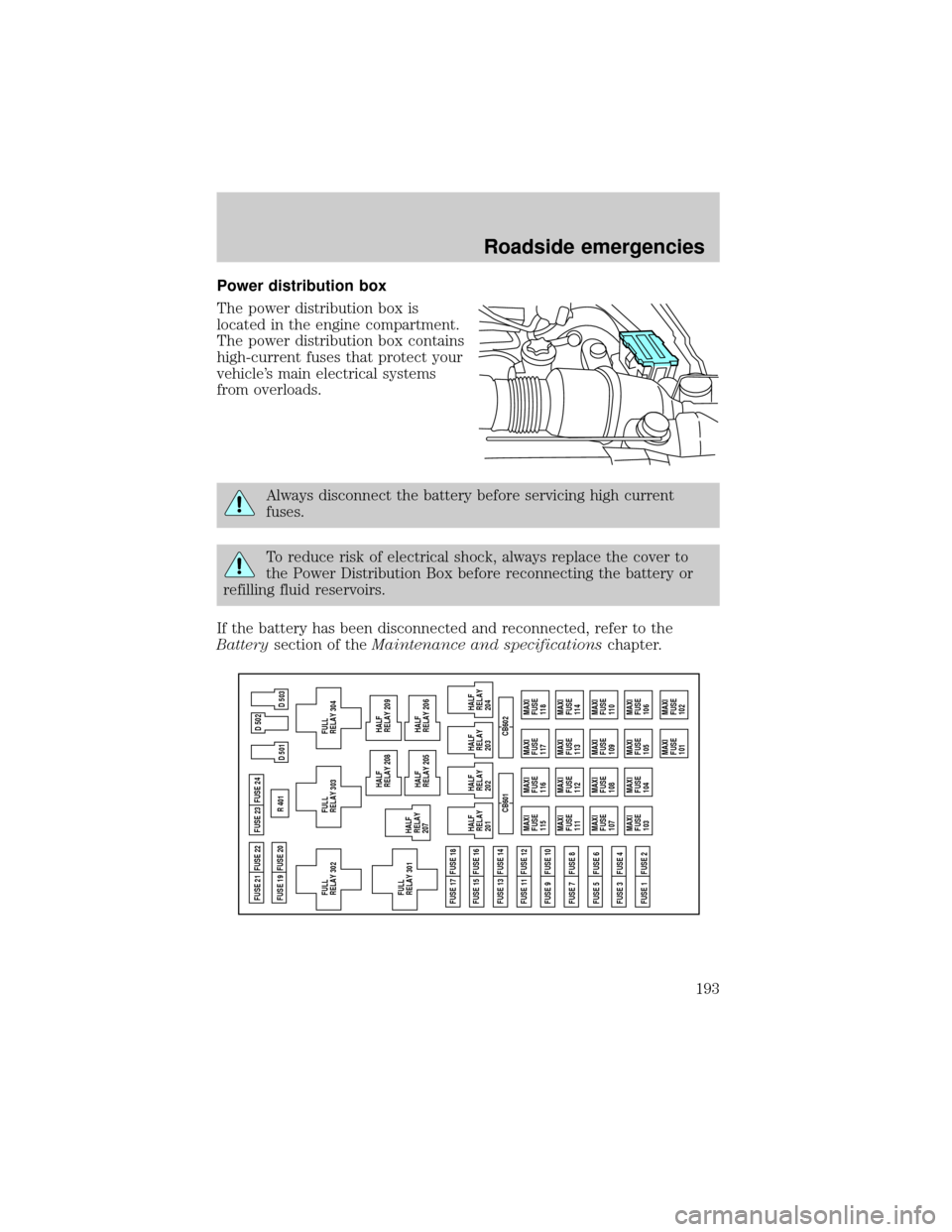
Power distribution box
The power distribution box is
located in the engine compartment.
The power distribution box contains
high-current fuses that protect your
vehicle's main electrical systems
from overloads.
Always disconnect the battery before servicing high current
fuses.
To reduce risk of electrical shock, always replace the cover to
the Power Distribution Box before reconnecting the battery or
refilling fluid reservoirs.
If the battery has been disconnected and reconnected, refer to the
Batterysection of theMaintenance and specificationschapter.
MAXI
FUSE
115MAXI
FUSE
116MAXI
FUSE
117
MAXI
FUSE
118
MAXI
FUSE
111MAXI
FUSE
112MAXI
FUSE
113
MAXI
FUSE
114
MAXI
FUSE
107MAXI
FUSE
108MAXI
FUSE
109
MAXI
FUSE
110
MAXI
FUSE
103MAXI
FUSE
104MAXI
FUSE
105
MAXI
FUSE
106
MAXI
FUSE
101MAXI
FUSE
102 CB601 CB602 FUSE 17 FUSE 18FUSE 21 FUSE 22
FUSE 19 FUSE 20FUSE 23
FULL
RELAY 302R 401
D 501 FUSE 24
FUSE 15 FUSE 16
FUSE 13 FUSE 14
FUSE 11 FUSE 12
FUSE 9 FUSE 10
FUSE 7 FUSE 8
FUSE 5 FUSE 6
FUSE 3 FUSE 4
FUSE 1 FUSE 2
D 503 D 502
FULL
RELAY 301HALF
RELAY
207
FULL
RELAY 303
FULL
RELAY 304
HALF
RELAY
201
HALF
RELAY
202HALF
RELAY 208
HALF
RELAY 209
HALF
RELAY 205
HALF
RELAY 206
HALF
RELAY
203
HALF
RELAY
204
Roadside emergencies
193