heater FORD EXPEDITION 2002 1.G Owners Manual
[x] Cancel search | Manufacturer: FORD, Model Year: 2002, Model line: EXPEDITION, Model: FORD EXPEDITION 2002 1.GPages: 280, PDF Size: 2.32 MB
Page 55 of 280
²Under snowy or dirty weather conditions, your vehicle's climate
control system should be left in the OFF position when the vehicle is
parked. This allows the climate control system to be free from
contamination of outside pollutants.
²If your vehicle has been parked with the windows closed during warm
weather conditions, the air conditioner will perform more efficiently in
cooling the vehicle if driven for two or three minutes with the
windows open. This will force most of the hot, stale air out of the
vehicle. Once the vehicle has been ªaired outº, operate the climate
control system as desired.
²Don't put objects under the front seat that will interfere with the
airflow to the rear seats.
²Remove any snow, ice or leaves from the air intake area at the base of
the windshield.
²Do not place objects over the defroster outlets. These objects can
block airflow and reduce your ability to see through your windshield.
Avoid placing small objects on top of the instrument panel. These
objects may fall down into the defroster outlets and block airflow, in
addition to damaging the climate control system.
To aid in side window defogging/demisting in cold weather conditions:
1. Select PNL²FLR
2. Set the temperature control to full heat
3. Set the fan speed control to HI
4. Direct the outer panel vents towards the side windows.
To increase airflow to the outer panel vents, close the central panel
vents.
Do not place objects on top of the instrument panel, as these
objects may become projectiles in a collision or sudden stop.
AUXILIARY A/C-HEATER CONTROLS (IF EQUIPPED)
Depending on your equipment package, your vehicle may be equipped
with auxiliary A/C-heater controls. The auxiliary A/C-heater feature
provides increased capacity to quickly heat or cool the vehicle. Besides
the driver's control panel for the front seat occupants, the second row
auxiliary A/C-heater controls allow the rear passengers to control the
Climate controls
55
Page 56 of 280
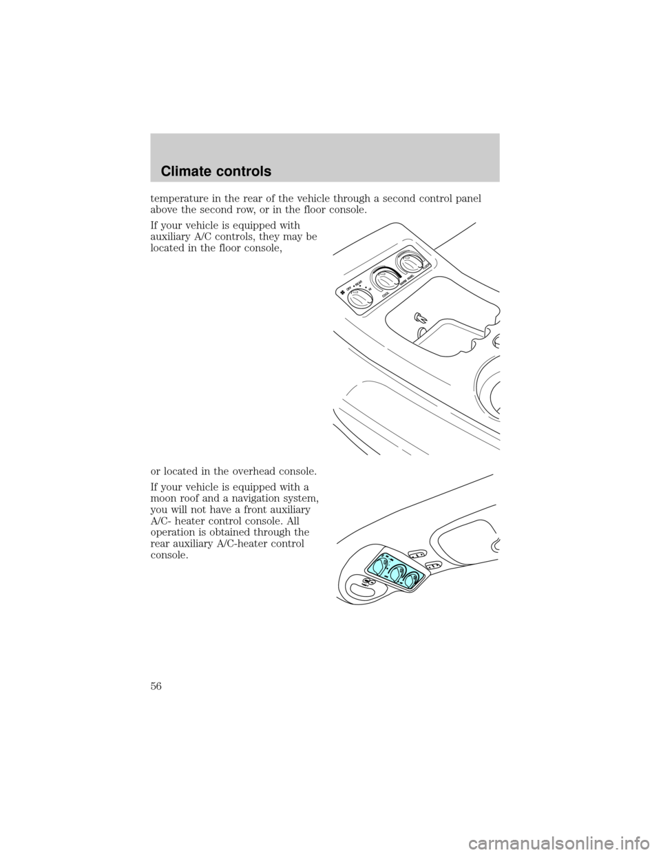
temperature in the rear of the vehicle through a second control panel
above the second row, or in the floor console.
If your vehicle is equipped with
auxiliary A/C controls, they may be
located in the floor console,
or located in the overhead console.
If your vehicle is equipped with a
moon roof and a navigation system,
you will not have a front auxiliary
A/C- heater control console. All
operation is obtained through the
rear auxiliary A/C-heater control
console.
HI OFF
REARWARM
COOL
PANEL
FLOOR
Climate controls
56
Page 57 of 280
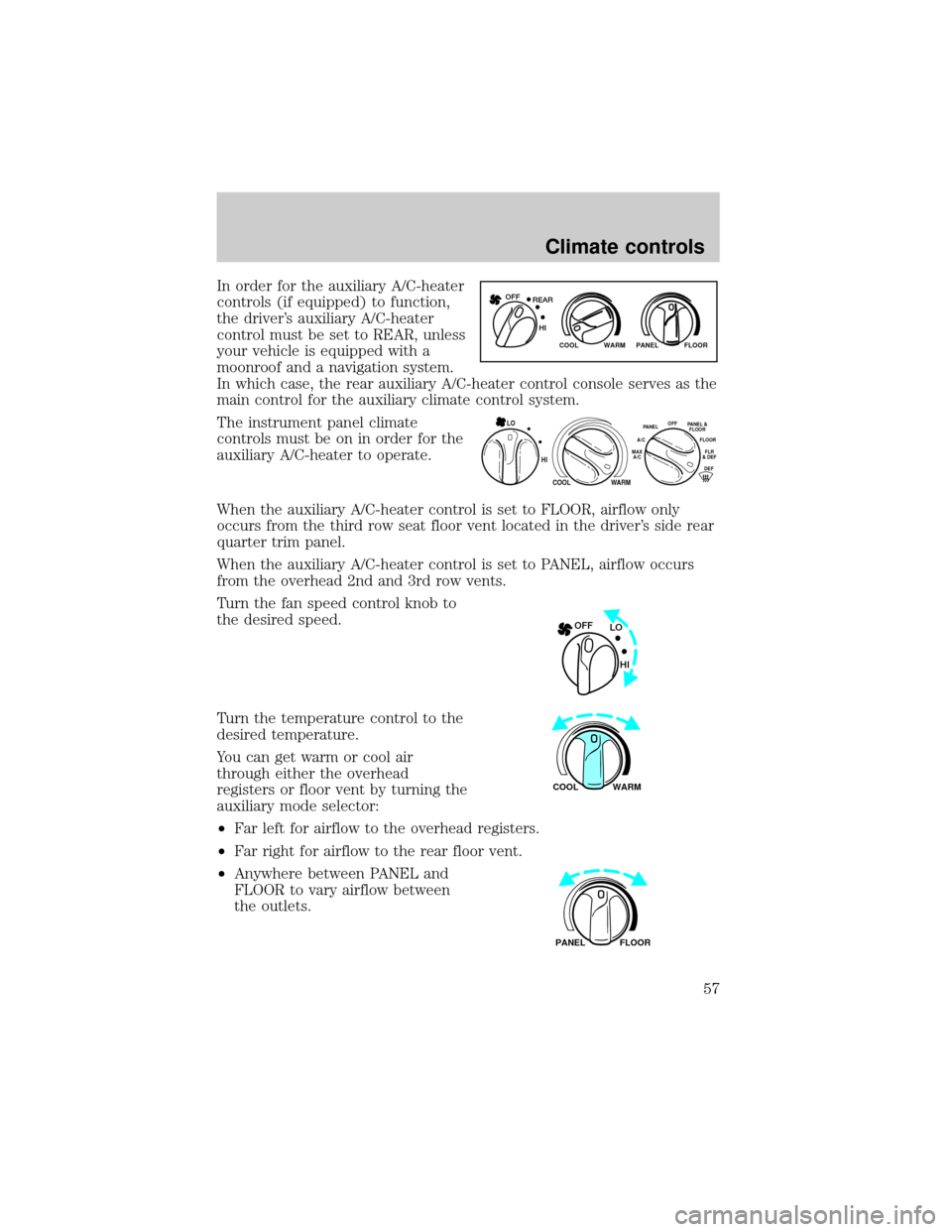
In order for the auxiliary A/C-heater
controls (if equipped) to function,
the driver's auxiliary A/C-heater
control must be set to REAR, unless
your vehicle is equipped with a
moonroof and a navigation system.
In which case, the rear auxiliary A/C-heater control console serves as the
main control for the auxiliary climate control system.
The instrument panel climate
controls must be on in order for the
auxiliary A/C-heater to operate.
When the auxiliary A/C-heater control is set to FLOOR, airflow only
occurs from the third row seat floor vent located in the driver's side rear
quarter trim panel.
When the auxiliary A/C-heater control is set to PANEL, airflow occurs
from the overhead 2nd and 3rd row vents.
Turn the fan speed control knob to
the desired speed.
Turn the temperature control to the
desired temperature.
You can get warm or cool air
through either the overhead
registers or floor vent by turning the
auxiliary mode selector:
²Far left for airflow to the overhead registers.
²Far right for airflow to the rear floor vent.
²Anywhere between PANEL and
FLOOR to vary airflow between
the outlets.
WARM PANEL FLOOR COOL
REAR OFF
HI
HI
COOL WARM
OFFPANELFLOOR
DEFFLR
& DEF A/C
MAX
A/CPANEL &
FLOOR
LO
LO OFF
HI
WARM COOL
FLOOR PANEL
Climate controls
57
Page 76 of 280
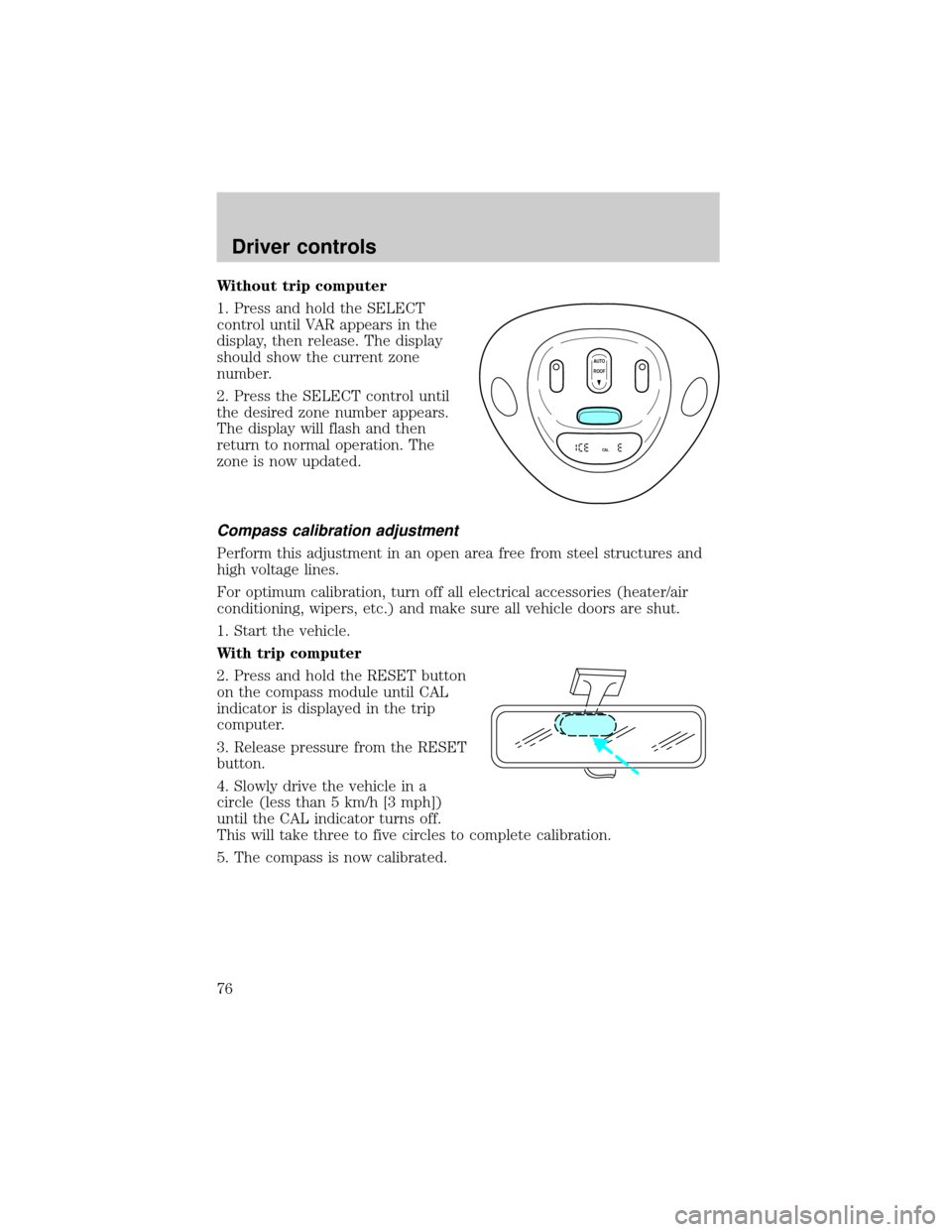
Without trip computer
1. Press and hold the SELECT
control until VAR appears in the
display, then release. The display
should show the current zone
number.
2. Press the SELECT control until
the desired zone number appears.
The display will flash and then
return to normal operation. The
zone is now updated.
Compass calibration adjustment
Perform this adjustment in an open area free from steel structures and
high voltage lines.
For optimum calibration, turn off all electrical accessories (heater/air
conditioning, wipers, etc.) and make sure all vehicle doors are shut.
1. Start the vehicle.
With trip computer
2. Press and hold the RESET button
on the compass module until CAL
indicator is displayed in the trip
computer.
3. Release pressure from the RESET
button.
4. Slowly drive the vehicle in a
circle (less than 5 km/h [3 mph])
until the CAL indicator turns off.
This will take three to five circles to complete calibration.
5. The compass is now calibrated.
AUTO
CAL
ROOF
Driver controls
76
Page 153 of 280
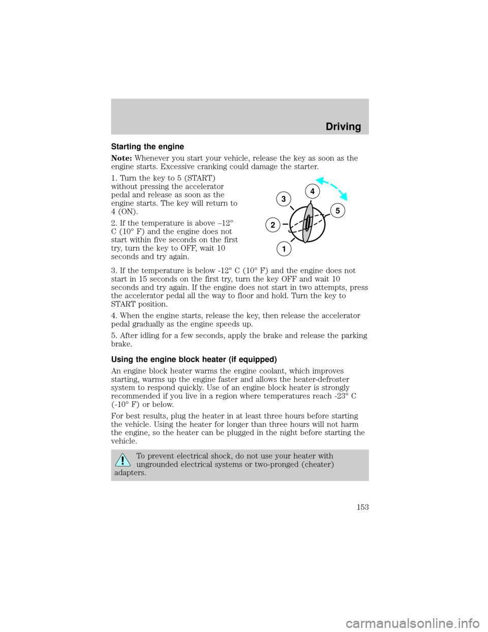
Starting the engine
Note:Whenever you start your vehicle, release the key as soon as the
engine starts. Excessive cranking could damage the starter.
1. Turn the key to 5 (START)
without pressing the accelerator
pedal and release as soon as the
engine starts. The key will return to
4 (ON).
2. If the temperature is above ±12É
C (10É F) and the engine does not
start within five seconds on the first
try, turn the key to OFF, wait 10
seconds and try again.
3. If the temperature is below -12É C (10É F) and the engine does not
start in 15 seconds on the first try, turn the key OFF and wait 10
seconds and try again. If the engine does not start in two attempts, press
the accelerator pedal all the way to floor and hold. Turn the key to
START position.
4. When the engine starts, release the key, then release the accelerator
pedal gradually as the engine speeds up.
5. After idling for a few seconds, apply the brake and release the parking
brake.
Using the engine block heater (if equipped)
An engine block heater warms the engine coolant, which improves
starting, warms up the engine faster and allows the heater-defroster
system to respond quickly. Use of an engine block heater is strongly
recommended if you live in a region where temperatures reach -23É C
(-10É F) or below.
For best results, plug the heater in at least three hours before starting
the vehicle. Using the heater for longer than three hours will not harm
the engine, so the heater can be plugged in the night before starting the
vehicle.
To prevent electrical shock, do not use your heater with
ungrounded electrical systems or two-pronged (cheater)
adapters.
3
2
1
5
4
Driving
153
Page 162 of 280
Driving with a 4±speed automatic transmission
Your vehicle's automatic transmission is equipped with a special shift
strategy that insures maximum heater performance during cold weather
operation.
When ambient temperature is ±5É C (23É F) or below and the engine
coolant temperature is below 38É C (100É F), light throttle upshifts may
be slightly delayed. Once the engine coolant temperature reaches 71É C
(160É F) the normal shift strategy will resume. This is normal operation
and will not affect the function or the durability of the transmission.
If the normal shift strategy does not resume once the engine
coolant temperature reaches the normal operating temperature,
or if the downshifts and other throttle conditions do not function
normally, see your dealer or a qualified service technician as soon
as possible.
Understanding gearshift positions
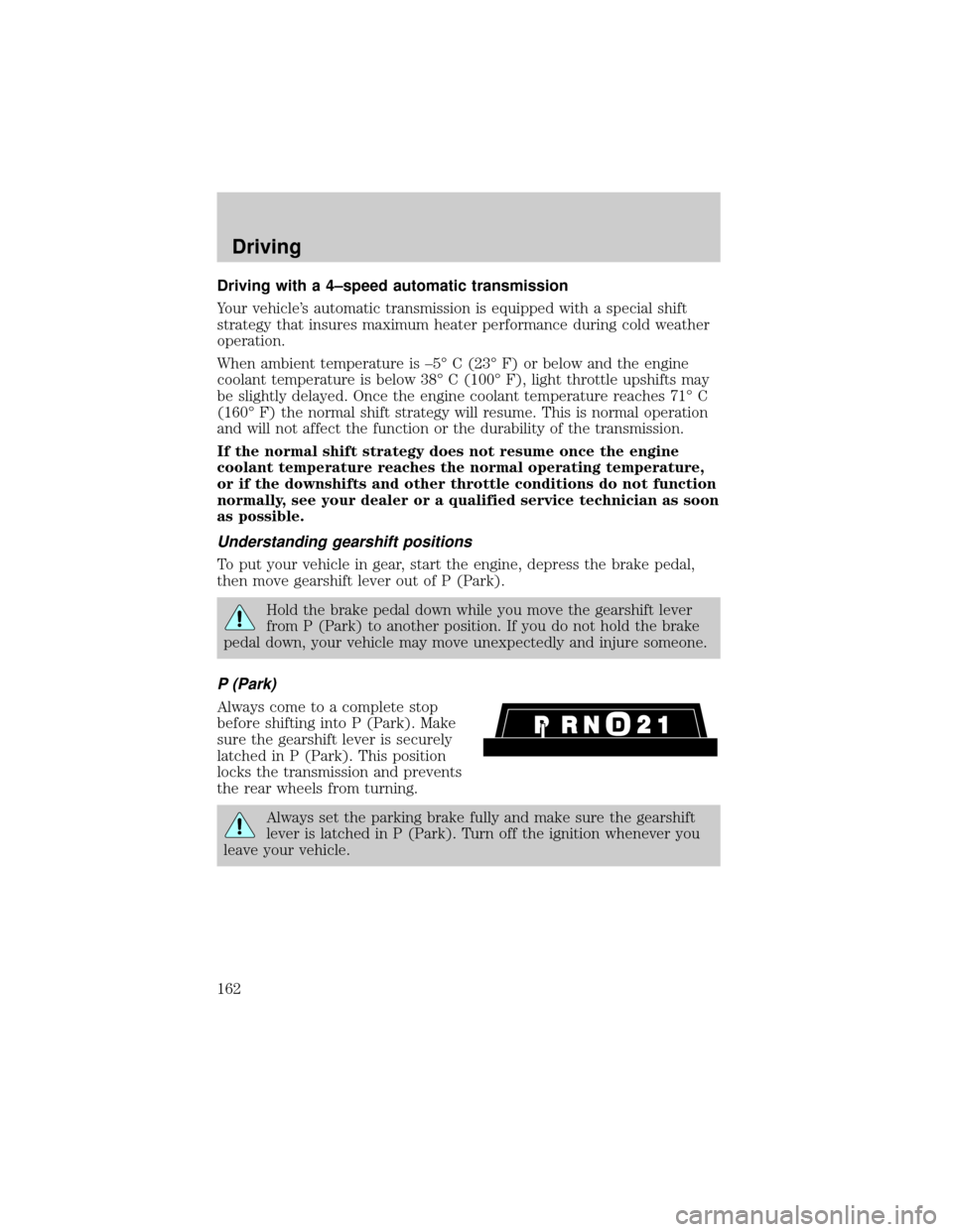
To put your vehicle in gear, start the engine, depress the brake pedal,
then move gearshift lever out of P (Park).
Hold the brake pedal down while you move the gearshift lever
from P (Park) to another position. If you do not hold the brake
pedal down, your vehicle may move unexpectedly and injure someone.
P (Park)
Always come to a complete stop
before shifting into P (Park). Make
sure the gearshift lever is securely
latched in P (Park). This position
locks the transmission and prevents
the rear wheels from turning.
Always set the parking brake fully and make sure the gearshift
lever is latched in P (Park). Turn off the ignition whenever you
leave your vehicle.
Driving
162
Page 203 of 280

4. Check all battery terminals and remove any excessive corrosion before
you attach the battery cables. Ensure that vent caps are tight and level.
5. Turn the heater fan on in both vehicles to protect any electrical
surges. Turn all other accessories off.
Connecting the jumper cables
1. Connect the positive (+) booster cable to the positive (+) terminal of
the discharged battery.
Note:In the illustrations,lightning boltsare used to designate the
assisting (boosting) battery.
2. Connect the other end of the positive (+) cable to the positive (+)
terminal of the assisting battery.
+–+–
+–+–
Roadside emergencies
203
Page 269 of 280

FORD ACCESSORIES FOR YOUR VEHICLE
A wide selection of genuine Ford accessories are available for your vehicle
through your local authorized Ford, Lincoln, Mercury or Ford of Canada
dealer. These quality accessories have been specifically engineered to fulfill
your automotive needs; they are custom designed to complement the style
and aerodynamic appearance of your vehicle. In addition, each accessory is
made from high quality materials and meets or exceeds Ford's rigorous
engineering and safety specifications. Ford Motor Company will repair or
replace any properly dealer-installed Ford accessory found to be defective in
factory-supplied materials or workmanship during the warranty period, as
well as any component damaged by the defective accessory. The accessory
will be warranted for whichever provides you the greatest benefit:
²12 months or 20 000 km (12 000 miles) (whichever occurs first), or
²The remainder of your new vehicle limited warranty.
This means that genuine Ford accessories purchased along with your
new vehicle and installed by the dealer are covered for the full length of
your New Vehicle's Limited Warranty Ð 3 years or 60 000 km (36 000
miles) (whichever occurs first). Contact your dealer for details and a
copy of the warranty.
Not all accessories are available for all models.
Vehicle Security
Styled wheel protector locks
Vehicle security systems
Comfort and convenience
Battery warmer
Cabin air filter
Cargo nets
Cargo organizers
Cargo storage box
Cargo trays
Carpeted cargo mat
Dash trim (wood grain)
Engine block heaters
Tire step
Accessories
269
Page 273 of 280

A
Accessory delay ..........................80
Air bag supplemental
restraint system ........132±133, 137
and child safety seats ............135
description ......................133, 137
disposal ....................................140
driver air bag ..................135, 138
indicator light ...........12, 137, 139
operation .........................135, 138
passenger air bag ...........135, 138
side air bag ..............................137
Air cleaner filter ...............254, 259
Air conditioning ..........................50
auxiliary heater and air
conditioner ................................55
manual heating and air
conditioning system .................47
Air suspension ...........................158
description ..............................158
warning light .............................12
Ambulance packages ....................7
Antifreeze
(see Engine coolant) ................234
Anti-lock brake system
(see Brakes) ..............................155
Anti-theft system
warning light .............................13
Armrests ....................................110
Automatic transmission
driving an automatic
overdrive .................................162
fluid, adding ............................252
fluid, checking ........................252
fluid, refill capacities ..............260
fluid, specification ..................265Auxiliary power point .................78
Axle
lubricant specifications ..263, 265
refill capacities ........................260
traction lok ..............................159
B
Battery .......................................231
acid, treating emergencies .....231
charging system
warning light .............................12
jumping a disabled battery ....202
maintenance-free ....................231
replacement, specifications ...259
servicing ..................................231
voltage gauge ............................16
Belt minder ...............................128
Brakes ........................................154
anti-lock ...................................155
anti-lock brake system (ABS)
warning light .....................11, 156
brake warning light ..................11
fluid, checking and adding ....251
fluid, refill capacities ..............260
fluid, specifications .........263, 265
lubricant specifications ..263, 265
parking ....................................156
pedals (see Power
adjustable foot pedals) ............82
shift interlock ..........................161
Break-in period .............................5
C
Capacities for refilling fluids ....260
Cassette tape player ...................18
CD changer .................................42
Certification Label ....................268
Index
273
Page 275 of 280

E
Emergencies, roadside
jump-starting ..........................202
Emission control system ..........248
Engine ................................265±266
check engine/
service engine soon light .........10
cleaning ...................................219
coolant .....................................234
fail-safe coolant ......................238
idle speed control ...................231
lubrication
specifications ..................263, 265
refill capacities ........................260
service points ..........................227
starting after a collision .........187
Engine block heater .................153
Engine oil ..................................228
change oil soon warning,
message center .......................228
checking and adding ..............228
dipstick ....................................228
filter, specifications ........230, 259
recommendations ...................230
refill capacities ........................260
specifications ..................263, 265
Exhaust fumes ..........................154
F
Fail safe cooling ........................238
Floor mats ...................................93
Fluid capacities .........................260
Foglamps .....................................59
Four-Wheel Drive
vehicles ................................14, 167
control trac .............................167description ..............................167
driving off road .......................169
electronic shift ........................168
indicator light ...........................14
preparing to
drive your vehicle ...................160
Fuel ............................................240
calculating fuel economy .......245
cap ...........................................242
capacity ...................................260
choosing the right fuel ...........243
comparisons with EPA fuel
economy estimates .................248
detergent in fuel .....................244
filling your vehicle
with fuel ..................240, 242, 245
filter, specifications ........244, 259
fuel pump shut-off switch .....187
gauge .........................................16
improving fuel economy ........245
low fuel warning light ..............12
octane rating ...........243, 265±266
quality ......................................243
running out of fuel .................244
safety information relating
to automotive fuels ................240
Fuses ..................................189±190
G
Garage door opener ..............72, 86
Gas cap (see Fuel cap) ............242
Gas mileage
(see Fuel economy) .................245
Gauges .........................................14
battery voltage gauge ...............16
engine coolant
temperature gauge ...................15
engine oil pressure gauge ........15
fuel gauge ..................................16
Index
275