fuel pump FORD EXPEDITION 2003 2.G Owners Manual
[x] Cancel search | Manufacturer: FORD, Model Year: 2003, Model line: EXPEDITION, Model: FORD EXPEDITION 2003 2.GPages: 320, PDF Size: 3.67 MB
Page 2 of 320
Seating and Safety Restraints 141
Seating 141
Safety restraints 155
Air bags 168
Child restraints 176
Driving 191
Starting 191
Brakes 195
Transmission operation 202
Vehicle loading 219
Trailer towing 221
Roadside Emergencies 227
Getting roadside assistance 227
Hazard flasher switch 228
Fuel pump shut-off switch 228
Fuses and relays 230
Changing tires 236
Jump starting 241
Wrecker towing 247
Customer Assistance 249
Reporting safety defects (U.S. only) 258
Table of Contents
2
Page 5 of 320
Fuel pump shut-off switchIn the event of an accident the
safety switch will automatically cut off the fuel supply to the
engine. The switch can also be activated through sudden vibration (e.g.
collision when parking). To reset the switch, refer to theFuel pump
shut-off switchin theRoadside emergencieschapter.
SAFETY AND ENVIRONMENT PROTECTION
Warning symbols in this guide
How can you reduce the risk of personal injury and prevent possible
damage to others, your vehicle and its equipment? In this guide, answers
to such questions are contained in comments highlighted by the warning
triangle symbol. These comments should be read and observed.
Warning symbols on your vehicle
When you see this symbol, it is
imperative that you consult the
relevant section of this guide before
touching or attempting adjustment
of any kind.
Protecting the environment
We must all play our part in
protecting the environment. Correct
vehicle usage and the authorized
disposal of waste cleaning and
lubrication materials are significant
steps towards this aim. Information in this respect is highlighted in this
guide with the tree symbol.
Introduction
5
Page 8 of 320
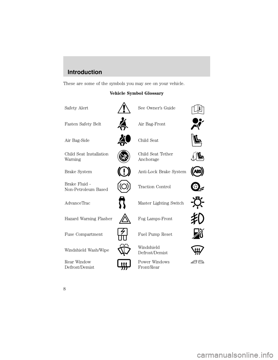
These are some of the symbols you may see on your vehicle.
Vehicle Symbol Glossary
Safety Alert
See Owner’s Guide
Fasten Safety BeltAir Bag-Front
Air Bag-SideChild Seat
Child Seat Installation
WarningChild Seat Tether
Anchorage
Brake SystemAnti-Lock Brake System
Brake Fluid -
Non-Petroleum BasedTraction Control
AdvanceTracMaster Lighting Switch
Hazard Warning FlasherFog Lamps-Front
Fuse CompartmentFuel Pump Reset
Windshield Wash/WipeWindshield
Defrost/Demist
Rear Window
Defrost/DemistPower Windows
Front/Rear
Introduction
8
Page 116 of 320
![FORD EXPEDITION 2003 2.G Owners Manual 8. Press the RESET control to start
the compass calibration function.
9. Slowly drive the vehicle in a
circle (less than 5 km/h [3 mph])
until the CIRCLE SLOWLY TO
CALIBRATE display changes to CALIBRA FORD EXPEDITION 2003 2.G Owners Manual 8. Press the RESET control to start
the compass calibration function.
9. Slowly drive the vehicle in a
circle (less than 5 km/h [3 mph])
until the CIRCLE SLOWLY TO
CALIBRATE display changes to CALIBRA](/img/11/4912/w960_4912-115.png)
8. Press the RESET control to start
the compass calibration function.
9. Slowly drive the vehicle in a
circle (less than 5 km/h [3 mph])
until the CIRCLE SLOWLY TO
CALIBRATE display changes to CALIBRATION COMPLETED. It will take
up to five circles to complete calibration.
10. The compass is now calibrated.
Average fuel economy (AFE)
Select this function from the INFO
menu to display your average fuel
economy in liters/100 km or
miles/gallon.
If you calculate your average fuel
economy by dividing liters of fuel used by 100 kilometers traveled (miles
traveled by gallons used), your figure may be different than displayed for
the following reasons:
•Your vehicle was not perfectly level during fill-up
•Differences in the automatic shut-off points on the fuel pumps at
service stations
•Variations in top-off procedure from one fill-up to another
•Rounding of the displayed values to the nearest 0.1 liter (gallon)
1. Drive the vehicle at least 8 km (5 miles) with the speed control
system engaged to display a stabilized average.
2. Record the highway fuel economy for future reference.
It is important to press the RESET control after setting the speed
control to get accurate highway fuel economy readings.
Driver Controls
116
Page 197 of 320
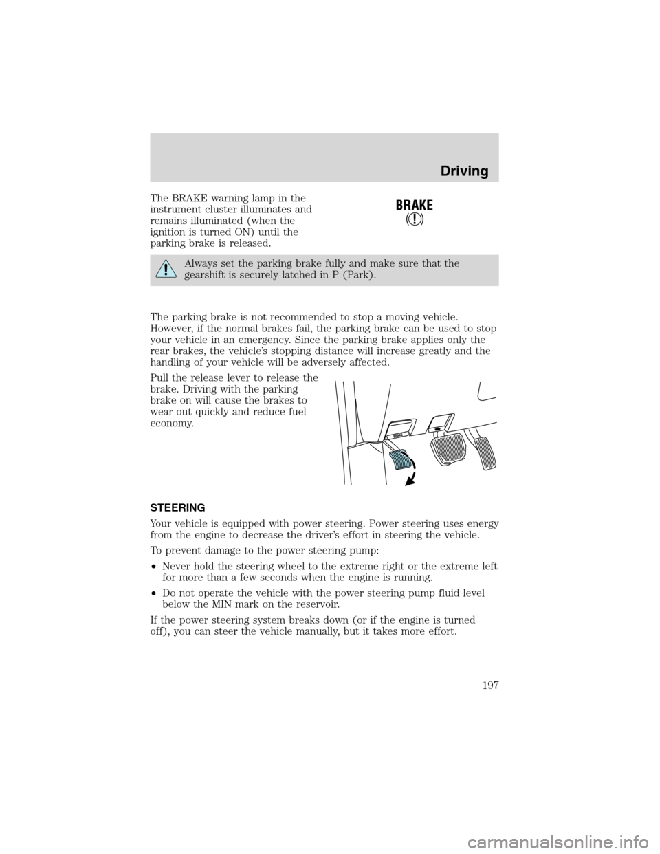
The BRAKE warning lamp in the
instrument cluster illuminates and
remains illuminated (when the
ignition is turned ON) until the
parking brake is released.
Always set the parking brake fully and make sure that the
gearshift is securely latched in P (Park).
The parking brake is not recommended to stop a moving vehicle.
However, if the normal brakes fail, the parking brake can be used to stop
your vehicle in an emergency. Since the parking brake applies only the
rear brakes, the vehicle’s stopping distance will increase greatly and the
handling of your vehicle will be adversely affected.
Pull the release lever to release the
brake. Driving with the parking
brake on will cause the brakes to
wear out quickly and reduce fuel
economy.
STEERING
Your vehicle is equipped with power steering. Power steering uses energy
from the engine to decrease the driver’s effort in steering the vehicle.
To prevent damage to the power steering pump:
•Never hold the steering wheel to the extreme right or the extreme left
for more than a few seconds when the engine is running.
•Do not operate the vehicle with the power steering pump fluid level
below the MIN mark on the reservoir.
If the power steering system breaks down (or if the engine is turned
off), you can steer the vehicle manually, but it takes more effort.
Driving
197
Page 228 of 320
Canadian customers who require roadside assistance, call
1–800–665–2006.
If you need to arrange roadside assistance for yourself, Ford Motor
Company will reimburse a reasonable amount. To obtain reimbursement
information, U.S. Ford or Mercury vehicles customers call
1-800-241-3673; Lincoln vehicle customers call 1–800–521–4140.
Canadian customers who need to obtain reimbursement information, call
1–800–665–2006.
ROADSIDE COVERAGE BEYOND BASIC WARRANTY
In the United States, you may purchase additional roadside assistance
coverage beyond this period through the Ford Auto Club by contacting
your Ford or Lincoln Mercury dealer.
Similarly in Canada, for uninterrupted Roadside Assistance coverage, you
may purchase extended coverage prior to your Basic Warranty’s Roadside
Assistance expiring. For more information and enrollment, contact
1–877–294–2582 or visit our website at www.ford.ca.
HAZARD FLASHER
Use only in an emergency to warn traffic of vehicle breakdown,
approaching danger, etc. The hazard flashers can be operated when the
ignition is off.
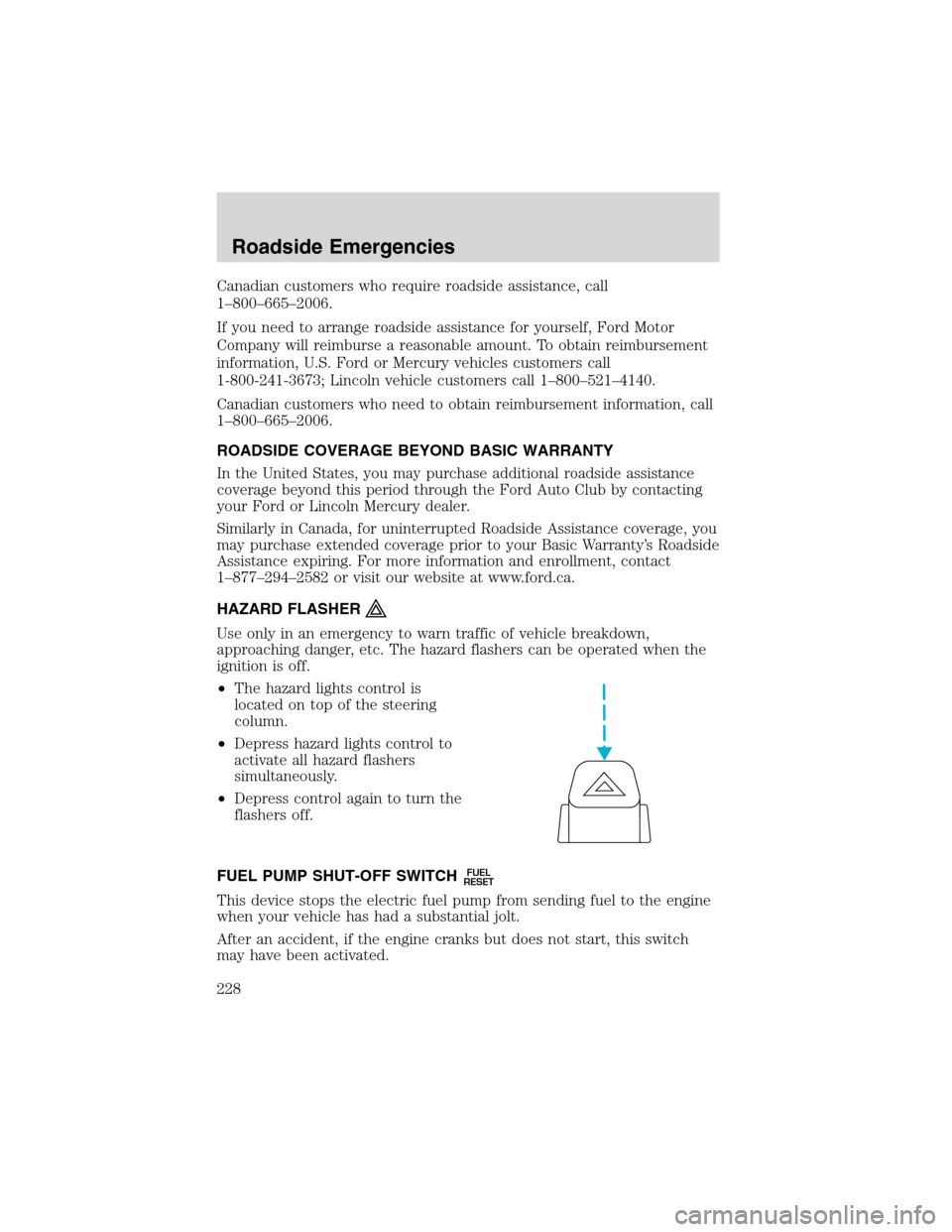
•The hazard lights control is
located on top of the steering
column.
•Depress hazard lights control to
activate all hazard flashers
simultaneously.
•Depress control again to turn the
flashers off.
FUEL PUMP SHUT-OFF SWITCH
FUEL
RESET
This device stops the electric fuel pump from sending fuel to the engine
when your vehicle has had a substantial jolt.
After an accident, if the engine cranks but does not start, this switch
may have been activated.
Roadside Emergencies
228
Page 229 of 320
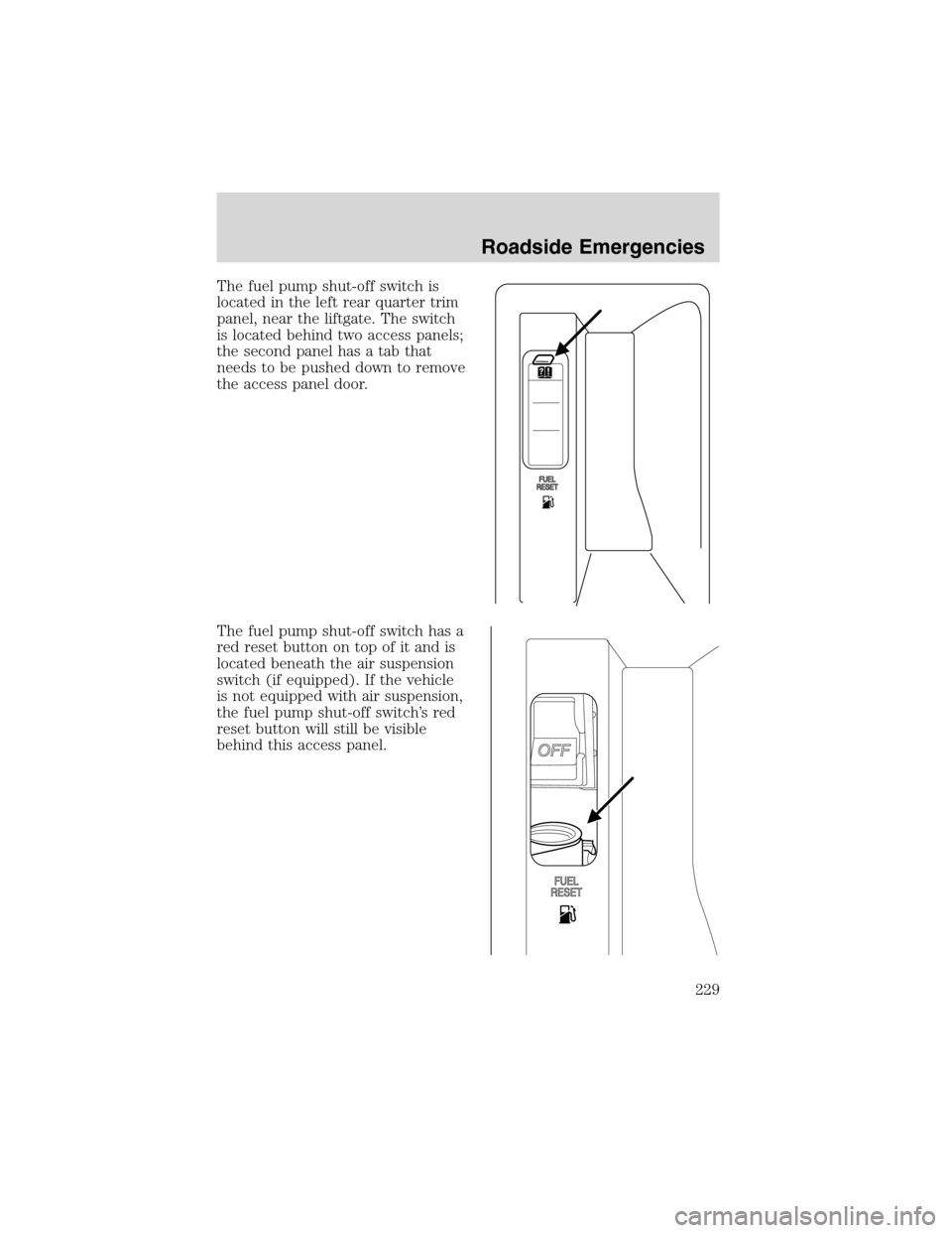
The fuel pump shut-off switch is
located in the left rear quarter trim
panel, near the liftgate. The switch
is located behind two access panels;
the second panel has a tab that
needs to be pushed down to remove
the access panel door.
The fuel pump shut-off switch has a
red reset button on top of it and is
located beneath the air suspension
switch (if equipped). If the vehicle
is not equipped with air suspension,
the fuel pump shut-off switch’s red
reset button will still be visible
behind this access panel.
Roadside Emergencies
229
Page 230 of 320
Use the following procedure to reset the fuel pump shut-off switch.
1. Turn the ignition to the OFF position.
2. Check the fuel system for leaks.
3. If no fuel leak is apparent, reset the fuel pump shut-off switch by
pushing in on the reset button.
4. Turn the ignition to the ON position. Pause for a few seconds and
return the key to the OFF position.
5. Make a further check for leaks in the fuel system.
FUSES AND RELAYS
Fuses
If electrical components in the
vehicle are not working, a fuse may
have blown. Blown fuses are
identified by a broken wire within
the fuse. Check the appropriate
fuses before replacing any electrical
components.
Note:Always replace a fuse with one that has the specified amperage
rating. Using a fuse with a higher amperage rating can cause severe wire
damage and could start a fire.
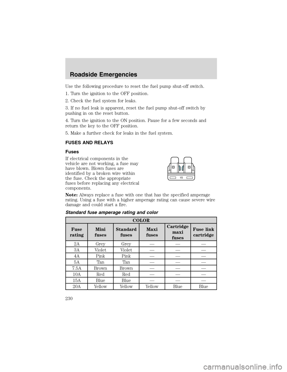
Standard fuse amperage rating and color
COLOR
Fuse
ratingMini
fusesStandard
fusesMaxi
fusesCartridge
maxi
fusesFuse link
cartridge
2A Grey Grey———
3A Violet Violet———
4A Pink Pink———
5A Tan Tan———
7.5A Brown Brown———
10A Red Red———
15A Blue Blue———
20A Yellow Yellow Yellow Blue Blue
15
Roadside Emergencies
230
Page 234 of 320
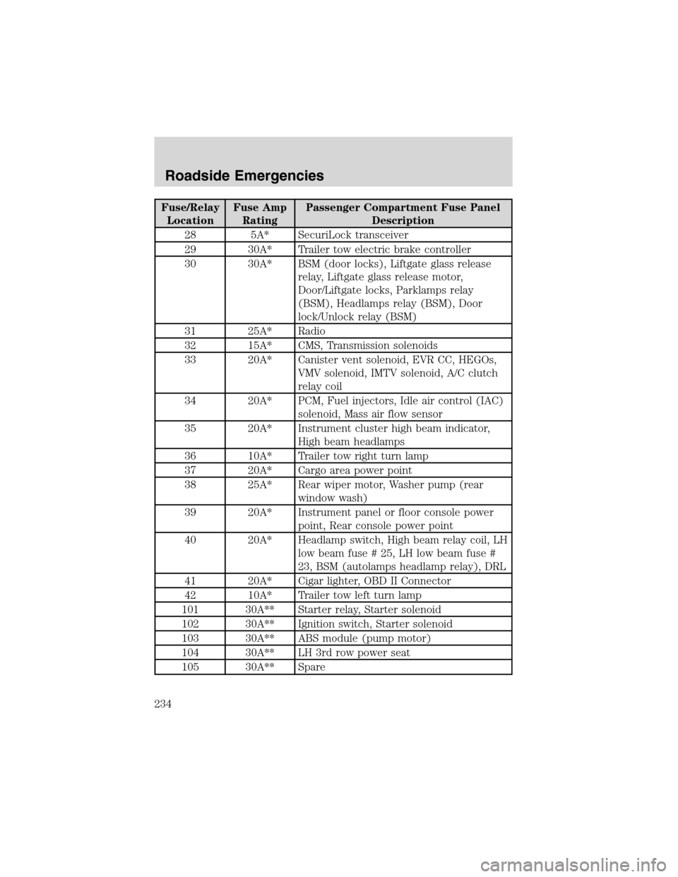
Fuse/Relay
LocationFuse Amp
RatingPassenger Compartment Fuse Panel
Description
28 5A* SecuriLock transceiver
29 30A* Trailer tow electric brake controller
30 30A* BSM (door locks), Liftgate glass release
relay, Liftgate glass release motor,
Door/Liftgate locks, Parklamps relay
(BSM), Headlamps relay (BSM), Door
lock/Unlock relay (BSM)
31 25A* Radio
32 15A* CMS, Transmission solenoids
33 20A* Canister vent solenoid, EVR CC, HEGOs,
VMV solenoid, IMTV solenoid, A/C clutch
relay coil
34 20A* PCM, Fuel injectors, Idle air control (IAC)
solenoid, Mass air flow sensor
35 20A* Instrument cluster high beam indicator,
High beam headlamps
36 10A* Trailer tow right turn lamp
37 20A* Cargo area power point
38 25A* Rear wiper motor, Washer pump (rear
window wash)
39 20A* Instrument panel or floor console power
point, Rear console power point
40 20A* Headlamp switch, High beam relay coil, LH
low beam fuse # 25, LH low beam fuse #
23, BSM (autolamps headlamp relay), DRL
41 20A* Cigar lighter, OBD II Connector
42 10A* Trailer tow left turn lamp
101 30A** Starter relay, Starter solenoid
102 30A** Ignition switch, Starter solenoid
103 30A** ABS module (pump motor)
104 30A** LH 3rd row power seat
105 30A** Spare
Roadside Emergencies
234
Page 236 of 320
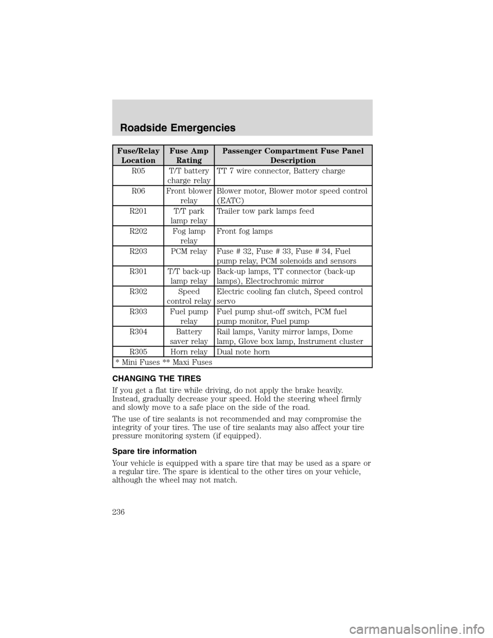
Fuse/Relay
LocationFuse Amp
RatingPassenger Compartment Fuse Panel
Description
R05 T/T battery
charge relayTT 7 wire connector, Battery charge
R06 Front blower
relayBlower motor, Blower motor speed control
(EATC)
R201 T/T park
lamp relayTrailer tow park lamps feed
R202 Fog lamp
relayFront fog lamps
R203 PCM relay Fuse # 32, Fuse # 33, Fuse # 34, Fuel
pump relay, PCM solenoids and sensors
R301 T/T back-up
lamp relayBack-up lamps, TT connector (back-up
lamps), Electrochromic mirror
R302 Speed
control relayElectric cooling fan clutch, Speed control
servo
R303 Fuel pump
relayFuel pump shut-off switch, PCM fuel
pump monitor, Fuel pump
R304 Battery
saver relayRail lamps, Vanity mirror lamps, Dome
lamp, Glove box lamp, Instrument cluster
R305 Horn relay Dual note horn
* Mini Fuses ** Maxi Fuses
CHANGING THE TIRES
If you get a flat tire while driving, do not apply the brake heavily.
Instead, gradually decrease your speed. Hold the steering wheel firmly
and slowly move to a safe place on the side of the road.
The use of tire sealants is not recommended and may compromise the
integrity of your tires. The use of tire sealants may also affect your tire
pressure monitoring system (if equipped).
Spare tire information
Your vehicle is equipped with a spare tire that may be used as a spare or
a regular tire. The spare is identical to the other tires on your vehicle,
although the wheel may not match.
Roadside Emergencies
236