sensor FORD EXPEDITION 2014 3.G User Guide
[x] Cancel search | Manufacturer: FORD, Model Year: 2014, Model line: EXPEDITION, Model: FORD EXPEDITION 2014 3.GPages: 519, PDF Size: 6.9 MB
Page 97 of 519
INTERIOR MIRROR
WARNING:Do not adjust the mirror when your vehicle is
moving.
Note:Do not clean the housing or glass of any mirror with harsh
abrasives, fuel or other petroleum or ammonia based cleaning products.
You can adjust the interior mirror to your preference. Some mirrors also
have a second pivot point. This lets you move the mirror head up or
down and from side to side.
Auto-Dimming Mirror
Note:Do not block the sensors on the front and back of the mirror.
Mirror performance may be affected. A rear center passenger or raised
rear center head restraint may also block light from reaching the sensor.
The mirror will dim automatically to reduce glare when bright lights are
detected from behind your vehicle. It will automatically return to normal
reflection when you select reverse gear to make sure you have a clear
view when backing up.
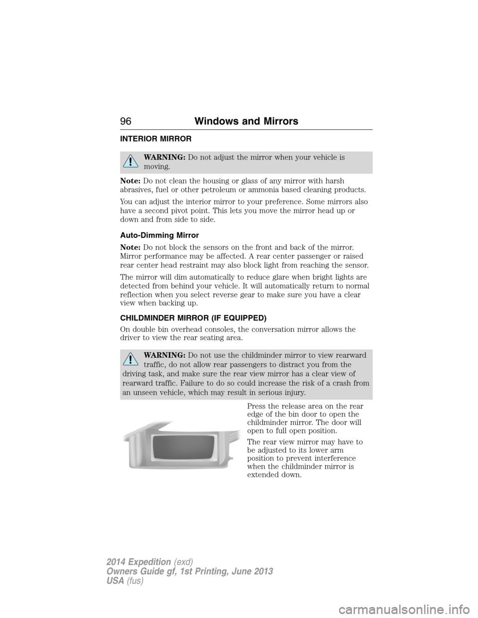
CHILDMINDER MIRROR (IF EQUIPPED)
On double bin overhead consoles, the conversation mirror allows the
driver to view the rear seating area.
WARNING:Do not use the childminder mirror to view rearward
traffic, do not allow rear passengers to distract you from the
driving task, and make sure the rear view mirror has a clear view of
rearward traffic. Failure to do so could increase the risk of a crash from
an unseen vehicle, which may result in serious injury.
Press the release area on the rear
edge of the bin door to open the
childminder mirror. The door will
open to full open position.
The rear view mirror may have to
be adjusted to its lower arm
position to prevent interference
when the childminder mirror is
extended down.
96Windows and Mirrors
2014 Expedition(exd)
Owners Guide gf, 1st Printing, June 2013
USA(fus)
Page 120 of 519
MyKey® Messages Action / Description
ADVTRAC ON
MYKEY SETTINGDisplayed when a MyKey® is in use when
trying to disable the AdvanceTrac® system
and the optional setting is on.
Park Aid Messages Action / Description
CHECK PARK AIDDisplayed when the transmission is in R
(Reverse).
Tire Messages Action / Description
LOW TIRE
PRESSUREDisplays when one or more tires on your
vehicle have low tire pressure.
TIRE PRESSURE
MONITOR FAULTDisplays when the tire pressure monitoring
system is malfunctioning. If the warning stays
on or continues to come on, contact your
authorized dealer.
TIRE PRESSURE
SENSOR FAULTDisplayed when a tire pressure sensor is
malfunctioning, or your spare tire is in use.
For more information on how the system
operates under these conditions refer to the
Tire Pressure Monitoring Systemin the
Wheels and Tireschapter for more
information. If the warning stays on or
continues to come on, contact your authorized
dealer as soon as possible.
Trailer Messages Action / Description
TRAILER SWAY
REDUCE SPEEDDisplayed when the trailer sway control has
detected trailer sway.
4WD Messages Action / Description
4X4 SHIFT IN
PROGRESSDisplayed when the 4X4 system is making a
shift.
FOR 4X4 LOW
SHIFT TO NDisplayed when 4X4 LOW is selected and the
vehicle is stopped.
FOR 4X4 LOW
SLOW TO 3 MPHDisplayed when 4X4 LOW is selected while the
vehicle is moving.
Information Displays11 9
2014 Expedition(exd)
Owners Guide gf, 1st Printing, June 2013
USA(fus)
Page 166 of 519
110 Volt AC Power Point (If Equipped)
WARNING:Do not keep electrical devices plugged in the power
point whenever the device is not in use. Do not use any
extension cord with the 110 volt AC power point, since it will defeat
the safety protection design. Doing so may cause the power point to
overload due to powering multiple devices that can reach beyond the
150–watt load limit and could result in fire or serious injury.
Note:The cap should always be closed whenever the power point outlet
is not in use.
Note:The power point will turn off after 13 minutes if the ignition is on
without the engine running. Keep the engine running to use the power
point.
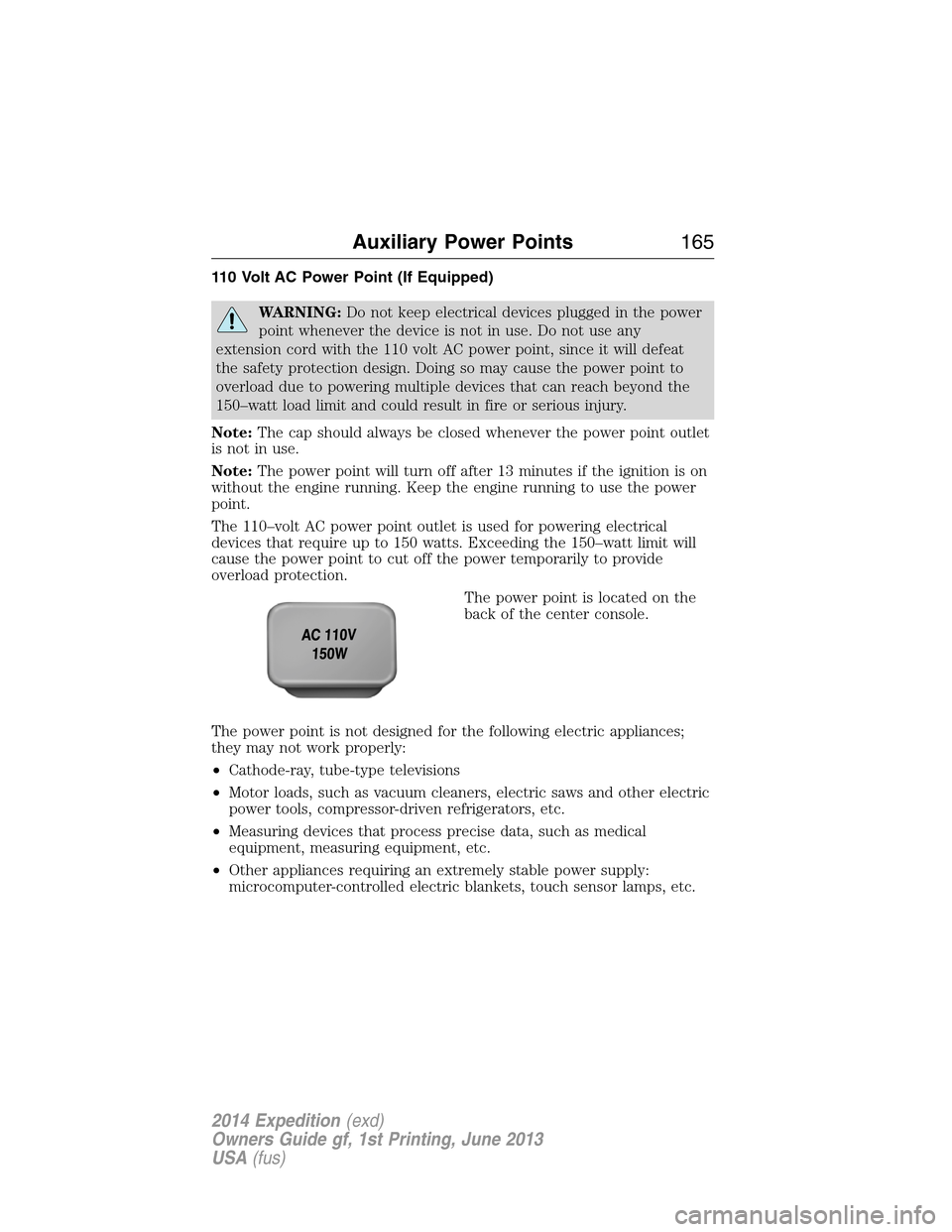
The 110–volt AC power point outlet is used for powering electrical
devices that require up to 150 watts. Exceeding the 150–watt limit will
cause the power point to cut off the power temporarily to provide
overload protection.
The power point is located on the
back of the center console.
The power point is not designed for the following electric appliances;
they may not work properly:
•Cathode-ray, tube-type televisions
•Motor loads, such as vacuum cleaners, electric saws and other electric
power tools, compressor-driven refrigerators, etc.
•Measuring devices that process precise data, such as medical
equipment, measuring equipment, etc.
•Other appliances requiring an extremely stable power supply:
microcomputer-controlled electric blankets, touch sensor lamps, etc.
Auxiliary Power Points165
2014 Expedition(exd)
Owners Guide gf, 1st Printing, June 2013
USA(fus)
Page 204 of 519
PRINCIPLES OF OPERATION
WARNING:Vehicle modifications involving braking system,
aftermarket roof racks, suspension, steering system, tire
construction or wheel and tire size may change the handling
characteristics of the vehicle and may adversely affect the performance
of the AdvanceTrac® system. In addition, installing any stereo
loudspeakers may interfere with and adversely affect the AdvanceTrac®
system. Install any aftermarket stereo loudspeaker as far as possible
from the front center console, the tunnel, and the front seats in order
to minimize the risk of interfering with the AdvanceTrac® sensors.
Reducing the effectiveness of the AdvanceTrac® system could lead to
an increased risk of loss of vehicle control, vehicle rollover, personal
injury and death.
WARNING:Remember that even advanced technology cannot
defy the laws of physics. It’s always possible to lose control of a
vehicle due to inappropriate driver input for the conditions. Aggressive
driving on any road condition can cause you to lose control of your
vehicle increasing the risk of personal injury or property damage.
Activation of the AdvanceTrac® system is an indication that at least
some of the tires have exceeded their ability to grip the road; this could
reduce the operator’s ability to control the vehicle potentially resulting
in a loss of vehicle control, vehicle rollover, personal injury and death.
If your AdvanceTrac® system activates, SLOW DOWN.
The AdvanceTrac® with Roll Stability Control™ system helps you keep
control of your vehicle when on a slippery surface. The electronic
stability control portion of the system helps avoid skids and lateral slides
and roll stability control helps avoid a vehicle rollover. The traction
control system helps avoid drive wheel spin and loss of traction. See the
Traction Controlchapter for details on traction control system
operation.
Stability Control203
2014 Expedition(exd)
Owners Guide gf, 1st Printing, June 2013
USA(fus)
Page 206 of 519

SENSING SYSTEM (IF EQUIPPED)
WARNING:To help avoid personal injury, please read and
understand the limitations of the system as contained in this
section. Sensing is only an aid for some (generally large and fixed)
objects when moving in reverse on a flat surface at parking speeds.
Traffic control systems, inclement weather, air brakes, and external
motors and fans may also affect the function of the sensing system; this
may include reduced performance or a false activation.
WARNING:To help avoid personal injury, always use caution
when in R (Reverse) and when using the sensing system.
WARNING:This system is not designed to prevent contact with
small or moving objects. The system is designed to provide a
warning to assist the driver in detecting large stationary objects to
avoid damaging the vehicle. The system may not detect smaller objects,
particularly those close to the ground.
WARNING:Certain add-on devices such as large trailer hitches,
bike or surfboard racks and any device that may block the normal
detection zone of the system, may create false beeps.
Note:Keep the sensors (located on the bumper/fascia) free from snow,
ice and large accumulations of dirt. If the sensors are covered, the
system’s accuracy can be affected. Do not clean the sensors with sharp
objects.
Note:If your vehicle sustains damage to the bumper/fascia, leaving it
misaligned or bent, the sensing zone may be altered causing inaccurate
measurement of obstacles or false alarms.
Note:If your vehicle is equipped with MyKey®, it is possible to prevent
turning the sensing system off. Refer to theMyKey®chapter.
The sensing system warns the driver of obstacles within a certain range
of the bumper area. The system turns on automatically whenever the
ignition is switched on.
When receiving a detection warning, the radio volume is reduced to a
predetermined level. After the warning goes away, the radio volume
returns to the previous level.
Parking Aids205
2014 Expedition(exd)
Owners Guide gf, 1st Printing, June 2013
USA(fus)
Page 207 of 519
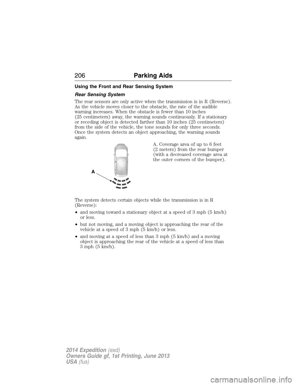
Using the Front and Rear Sensing System
Rear Sensing System
The rear sensors are only active when the transmission is in R (Reverse).
As the vehicle moves closer to the obstacle, the rate of the audible
warning increases. When the obstacle is fewer than 10 inches
(25 centimeters) away, the warning sounds continuously. If a stationary
or receding object is detected farther than 10 inches (25 centimeters)
from the side of the vehicle, the tone sounds for only three seconds.
Once the system detects an object approaching, the warning sounds
again.
A. Coverage area of up to 6 feet
(2 meters) from the rear bumper
(with a decreased coverage area at
the outer corners of the bumper).
The system detects certain objects while the transmission is in R
(Reverse):
•and moving toward a stationary object at a speed of 3 mph (5 km/h)
or less.
•but not moving, and a moving object is approaching the rear of the
vehicle at a speed of 3 mph (5 km/h) or less.
•and moving at a speed of less than 3 mph (5 km/h) and a moving
object is approaching the rear of the vehicle at a speed of less than
3 mph (5 km/h).
A
206Parking Aids
2014 Expedition(exd)
Owners Guide gf, 1st Printing, June 2013
USA(fus)
Page 208 of 519
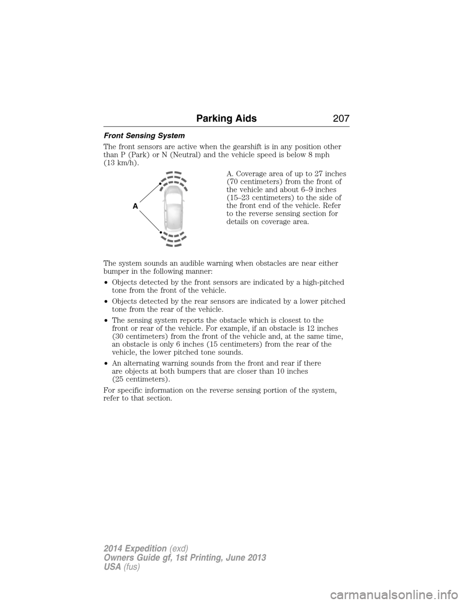
Front Sensing System
The front sensors are active when the gearshift is in any position other
than P (Park) or N (Neutral) and the vehicle speed is below 8 mph
(13 km/h).
A. Coverage area of up to 27 inches
(70 centimeters) from the front of
the vehicle and about 6–9 inches
(15–23 centimeters) to the side of
the front end of the vehicle. Refer
to the reverse sensing section for
details on coverage area.
The system sounds an audible warning when obstacles are near either
bumper in the following manner:
•Objects detected by the front sensors are indicated by a high-pitched
tone from the front of the vehicle.
•Objects detected by the rear sensors are indicated by a lower pitched
tone from the rear of the vehicle.
•The sensing system reports the obstacle which is closest to the
front or rear of the vehicle. For example, if an obstacle is 12 inches
(30 centimeters) from the front of the vehicle and, at the same time,
an obstacle is only 6 inches (15 centimeters) from the rear of the
vehicle, the lower pitched tone sounds.
•An alternating warning sounds from the front and rear if there
are objects at both bumpers that are closer than 10 inches
(25 centimeters).
For specific information on the reverse sensing portion of the system,
refer to that section.
A
Parking Aids207
2014 Expedition(exd)
Owners Guide gf, 1st Printing, June 2013
USA(fus)
Page 269 of 519
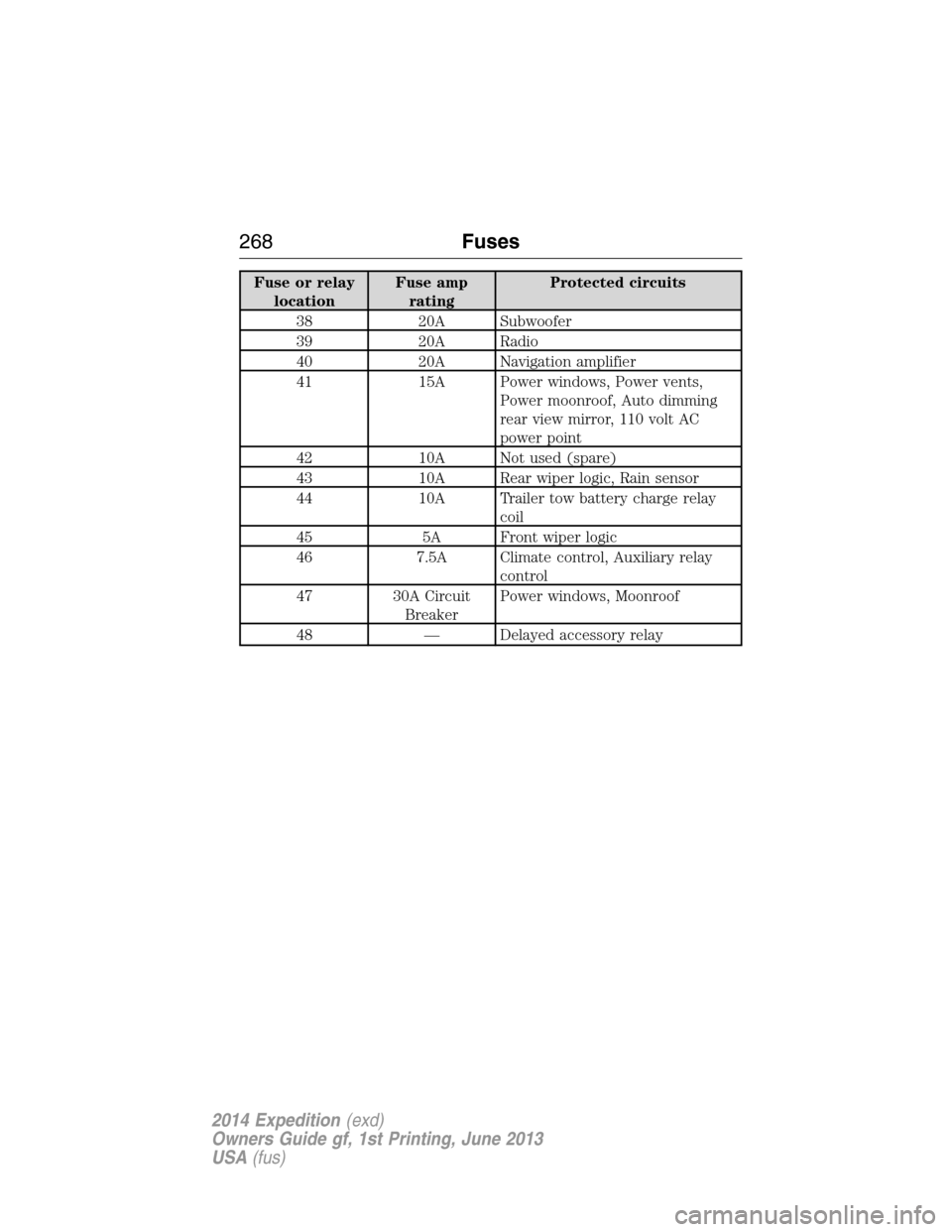
Fuse or relay
locationFuse amp
ratingProtected circuits
38 20A Subwoofer
39 20A Radio
40 20A Navigation amplifier
41 15A Power windows, Power vents,
Power moonroof, Auto dimming
rear view mirror, 110 volt AC
power point
42 10A Not used (spare)
43 10A Rear wiper logic, Rain sensor
44 10A Trailer tow battery charge relay
coil
45 5A Front wiper logic
46 7.5A Climate control, Auxiliary relay
control
47 30A Circuit
BreakerPower windows, Moonroof
48 — Delayed accessory relay
268Fuses
2014 Expedition(exd)
Owners Guide gf, 1st Printing, June 2013
USA(fus)
Page 285 of 519
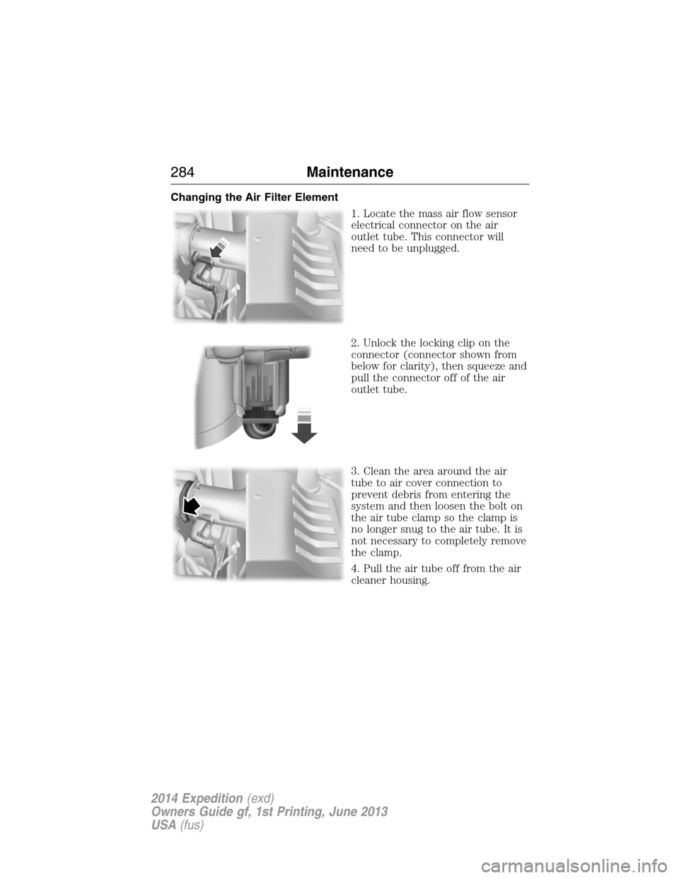
Changing the Air Filter Element
1. Locate the mass air flow sensor
electrical connector on the air
outlet tube. This connector will
need to be unplugged.
2. Unlock the locking clip on the
connector (connector shown from
below for clarity), then squeeze and
pull the connector off of the air
outlet tube.
3. Clean the area around the air
tube to air cover connection to
prevent debris from entering the
system and then loosen the bolt on
the air tube clamp so the clamp is
no longer snug to the air tube. It is
not necessary to completely remove
the clamp.
4. Pull the air tube off from the air
cleaner housing.
284Maintenance
2014 Expedition(exd)
Owners Guide gf, 1st Printing, June 2013
USA(fus)
Page 286 of 519
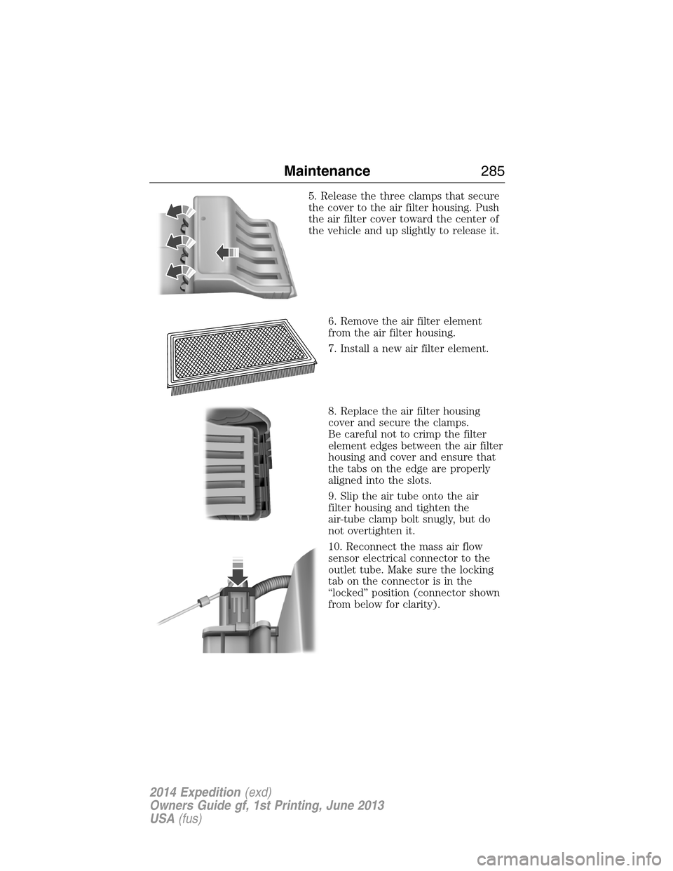
5. Release the three clamps that secure
the cover to the air filter housing. Push
the air filter cover toward the center of
the vehicle and up slightly to release it.
6. Remove the air filter element
from the air filter housing.
7. Install a new air filter element.
8. Replace the air filter housing
cover and secure the clamps.
Be careful not to crimp the filter
element edges between the air filter
housing and cover and ensure that
the tabs on the edge are properly
aligned into the slots.
9. Slip the air tube onto the air
filter housing and tighten the
air-tube clamp bolt snugly, but do
not overtighten it.
10. Reconnect the mass air flow
sensor electrical connector to the
outlet tube. Make sure the locking
tab on the connector is in the
“locked” position (connector shown
from below for clarity).
Maintenance285
2014 Expedition(exd)
Owners Guide gf, 1st Printing, June 2013
USA(fus)