fuse FORD EXPEDITION 2017 3.G Owners Manual
[x] Cancel search | Manufacturer: FORD, Model Year: 2017, Model line: EXPEDITION, Model: FORD EXPEDITION 2017 3.GPages: 500, PDF Size: 4.83 MB
Page 7 of 500
Economical Driving......................................218
Driving Through Water................................219
Floor Mats........................................................219
Roadside Emergencies
Roadside Assistance
...................................221
Hazard Warning Flashers..........................222
Fuel Shutoff
...................................................222
Jump Starting the Vehicle.........................223
Customer Assistance
Getting the Services You Need...............226
In California (U.S. Only).............................227
The Better Business Bureau (BBB) Auto Line Program (U.S. Only)
......................228
Utilizing the Mediation/Arbitration Program (Canada Only).......................229
Getting Assistance Outside the U.S. and Canada........................................................229
Ordering Additional Owner's Literature....................................................230
Reporting Safety Defects (U.S. Only)..............................................................231
Reporting Safety Defects (Canada Only)..............................................................231
Fuses
Fuse Specification Chart...........................233
Changing a Fuse
............................................241
Maintenance
General Information
...................................243
Opening and Closing the Hood..............243
Under Hood Overview...............................244
Engine Oil Dipstick......................................245
Engine Oil Check
..........................................245
Oil Change Indicator Reset......................246
Engine Coolant Check................................247
Automatic Transmission Fluid Check............................................................251
Transfer Case Fluid Check.........................251 Brake Fluid Check........................................252
Washer Fluid Check
....................................252
Fuel Filter
........................................................253
Changing the 12V Battery.........................253
Checking the Wiper Blades......................255
Changing the Wiper Blades.....................255
Adjusting the Headlamps........................256
Removing a Headlamp
..............................257
Changing a Bulb...........................................257
Bulb Specification Chart..........................260
Changing the Engine Air Filter.................262
Vehicle Care
General Information
...................................264
Cleaning Products
.......................................264
Cleaning the Exterior
..................................265
Waxing
.............................................................266
Cleaning the Engine
...................................266
Cleaning the Windows and Wiper Blades..........................................................267
Cleaning the Interior...................................267
Cleaning the Instrument Panel and Instrument Cluster Lens.......................268
Cleaning Leather Seats.............................268
Repairing Minor Paint Damage
...............270
Cleaning the Alloy Wheels.......................270
Vehicle Storage.............................................270
Wheels and Tires
General Information....................................273
Tire Care..........................................................276
Using Snow Chains
......................................291
Tire Pressure Monitoring System...........292
Changing a Road Wheel
............................297
Technical Specifications
...........................302
Capacities and Specific- ations
Engine Specifications
................................304
Motorcraft Parts
..........................................304
4
Expedition (TB7) Canada/United States of America, enUSA, Edition date: 03/2016, First Printing Table of Contents
Page 11 of 500
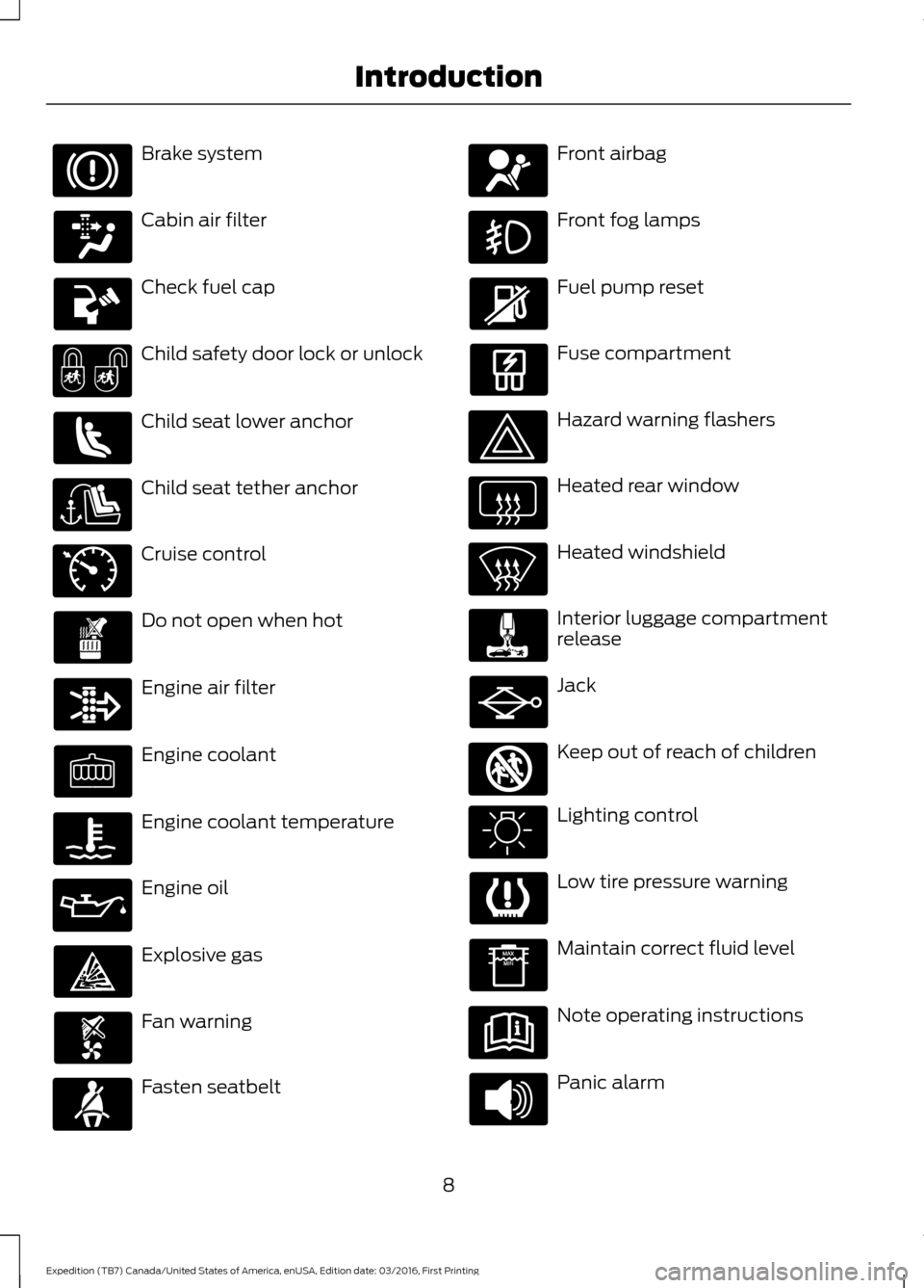
Brake system
Cabin air filter
Check fuel cap
Child safety door lock or unlock
Child seat lower anchor
Child seat tether anchor
Cruise control
Do not open when hot
Engine air filter
Engine coolant
Engine coolant temperature
Engine oil
Explosive gas
Fan warning
Fasten seatbelt Front airbag
Front fog lamps
Fuel pump reset
Fuse compartment
Hazard warning flashers
Heated rear window
Heated windshield
Interior luggage compartment
release
Jack
Keep out of reach of children
Lighting control
Low tire pressure warning
Maintain correct fluid level
Note operating instructions
Panic alarm
8
Expedition (TB7) Canada/United States of America, enUSA, Edition date: 03/2016, First Printing Introduction E71340 E161353
Page 39 of 500
PRINCIPLE OF OPERATION
WARNINGS
Airbags do not inflate slowly or
gently, and the risk of injury from a
deploying airbag is the greatest close
to the trim covering the airbag module. All occupants of your vehicle,
including the driver, should always
properly wear their safety belts, even
when an airbag supplemental restraint
system is provided. Failure to properly wear
your safety belt could seriously increase
the risk of injury or death. Always transport children 12 years
old and under in the back seat and
always properly use appropriate
child restraints. Failure to follow this could
seriously increase the risk of injury or death. Never place your arm over the airbag
module as a deploying airbag can
result in serious arm fractures or
other injuries. Airbags can kill or injure a child in a
child seat. Never place a rear-facing
child seat in front of an active airbag.
If you must use a forward-facing child seat
in the front seat, move the seat upon which
the child seat is installed all the way back. Do not attempt to service, repair, or
modify the airbag supplemental
restraint systems or its fuses as you
could be seriously injured or killed. Contact
your authorized dealer as soon as possible. Several airbag system components
get hot after inflation. To avoid risk
of injury, do not touch them after
inflation. If the airbag has deployed, the airbag
will not function again and must be
replaced immediately. If the airbag
is not replaced, the unrepaired area will
increase the risk of injury in a crash. The airbags are a supplemental restraint
system and are designed to work with the
safety belts to help protect the driver and
right front passenger from certain upper
body injuries. Airbags do not inflate slowly;
there is a risk of injury from a deploying
airbag.
Note:
You will hear a loud bang and see a
cloud of harmless powdery residue if an
airbag deploys. This is normal.
The airbags inflate and deflate rapidly
upon activation. After airbag deployment,
it is normal to notice a smoke-like, powdery
residue or smell the burnt propellant. This
may consist of cornstarch, talcum powder
(to lubricate the bag) or sodium
compounds (for example, baking soda)
that result from the combustion process
that inflates the airbag. Small amounts of
sodium hydroxide may be present which
may irritate the skin and eyes, but none of
the residue is toxic.
While the system is designed to help
reduce serious injuries, contact with a
deploying airbag may also cause abrasions
or swelling. Temporary hearing loss is also
a possibility as a result of the noise
associated with a deploying airbag.
Because airbags must inflate rapidly and
with considerable force, there is the risk of
death or serious injuries such as fractures,
facial and eye injuries or internal injuries,
particularly to occupants who are not
properly restrained or are otherwise out of
position at the time of airbag deployment.
Thus, it is extremely important that
occupants be properly restrained as far
away from the airbag module as possible
while maintaining vehicle control.
Routine maintenance of the airbags is not
required.
36
Expedition (TB7) Canada/United States of America, enUSA, Edition date: 03/2016, First Printing Supplementary Restraints System
Page 42 of 500
WARNINGS
Do not attempt to service, repair, or
modify the airbag, its fuses or the
seat cover on a seat containing an
airbag as you could be seriously injured or
killed. Contact your authorized dealer as
soon as possible. If the side airbag has deployed, the
airbag will not function again. The
side airbag system (including the
seat) must be inspected and serviced by
an authorized dealer. If the airbag is not
replaced, the unrepaired area will increase
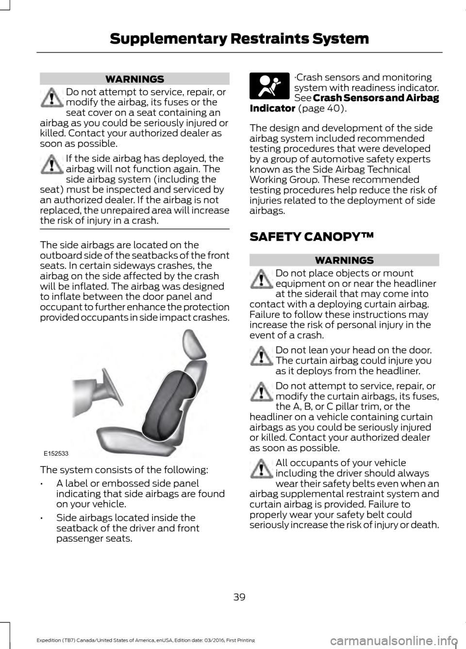
the risk of injury in a crash. The side airbags are located on the
outboard side of the seatbacks of the front
seats. In certain sideways crashes, the
airbag on the side affected by the crash
will be inflated. The airbag was designed
to inflate between the door panel and
occupant to further enhance the protection
provided occupants in side impact crashes.
The system consists of the following:
•
A label or embossed side panel
indicating that side airbags are found
on your vehicle.
• Side airbags located inside the
seatback of the driver and front
passenger seats. ·Crash sensors and monitoring
system with readiness indicator.
See Crash Sensors and Airbag
Indicator (page 40).
The design and development of the side
airbag system included recommended
testing procedures that were developed
by a group of automotive safety experts
known as the Side Airbag Technical
Working Group. These recommended
testing procedures help reduce the risk of
injuries related to the deployment of side
airbags.
SAFETY CANOPY™ WARNINGS
Do not place objects or mount
equipment on or near the headliner
at the siderail that may come into
contact with a deploying curtain airbag.
Failure to follow these instructions may
increase the risk of personal injury in the
event of a crash. Do not lean your head on the door.
The curtain airbag could injure you
as it deploys from the headliner.
Do not attempt to service, repair, or
modify the curtain airbags, its fuses,
the A, B, or C pillar trim, or the
headliner on a vehicle containing curtain
airbags as you could be seriously injured
or killed. Contact your authorized dealer
as soon as possible. All occupants of your vehicle
including the driver should always
wear their safety belts even when an
airbag supplemental restraint system and
curtain airbag is provided. Failure to
properly wear your safety belt could
seriously increase the risk of injury or death.
39
Expedition (TB7) Canada/United States of America, enUSA, Edition date: 03/2016, First Printing Supplementary Restraints SystemE152533
Page 144 of 500
12 Volt DC Power Point
WARNINGS
Do not plug optional electrical
accessories into the cigar lighter
socket. Incorrect use of the cigar
lighter can cause damage not covered by
the vehicle warranty, and can result in fire
or serious injury. Do not use a power point for
operating a cigar lighter. Incorrect
use of the power points can cause
damage not covered by the vehicle
warranty, and can result in fire or serious
injury. Note:
When you switch the ignition on, you
can use the socket to power 12 volt
appliances with a maximum current rating
of 15 amps.
If the power supply does not work after you
switch the ignition off, switch the ignition
on.
Note: Do not hang any accessory from the
accessory plug.
Note: Do not use the power point over the
vehicle capacity of 12 volt DC 180 watts or
a fuse may blow.
Note: Always keep the power point caps
closed when not in use.
Do not insert objects other than an
accessory plug into the power point. This
will damage the power point and blow the
fuse.
Run the vehicle for full capacity use of the
power point.
To prevent the battery from running out of
charge:
• Do not use the power point longer than
necessary when the vehicle is not
running.
• Do not leave devices plugged in
overnight or when you park your vehicle
for extended periods. Locations
Power points may be in the following
locations:
•
On the lower instrument panel.
• Inside the center console.
• On the rear of the center console.
• In the rear cargo area.
110 Volt AC Power Point (If Equipped) WARNING
Do not keep electrical devices
plugged in the power point whenever
the device is not in use. Do not use
any extension cord with the 110 volt AC
power point, since it will defeat the safety
protection design. Doing so may cause the
power point to overload due to powering
multiple devices that can reach beyond
the 150 watt load limit and could result in
fire or serious injury. Note:
The power point will turn off when
the ignition is switched off or the battery
voltage drops below 11 volts.
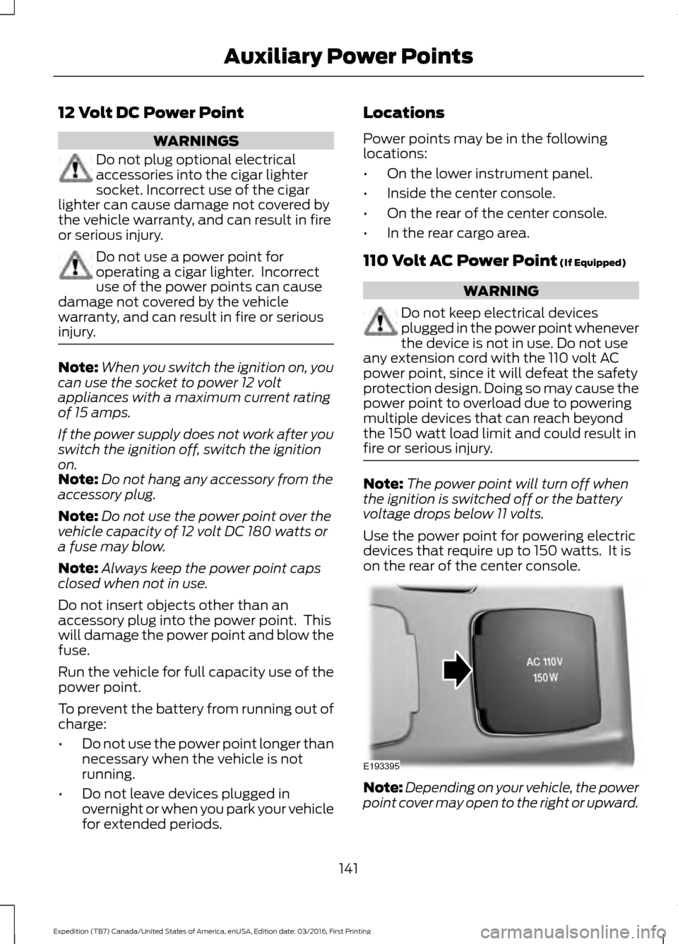
Use the power point for powering electric
devices that require up to 150 watts. It is
on the rear of the center console. Note:
Depending on your vehicle, the power
point cover may open to the right or upward.
141
Expedition (TB7) Canada/United States of America, enUSA, Edition date: 03/2016, First Printing Auxiliary Power PointsE193395
Page 155 of 500
Filling a Portable Fuel Container
Use the following guidelines to avoid
electrostatic charge build-up, which can
produce a spark, when filling an
ungrounded fuel container:
•
Only use an approved fuel container to
transfer fuel to your vehicle. Place the
container on the ground when filling it.
• Do not fill a fuel container when it is
inside your vehicle (including the cargo
area).
• Keep the fuel pump nozzle in contact
with the fuel container when filling it.
• Do not use a device that holds the fuel
pump nozzle lever in the fill position.
Adding Fuel From a Portable Fuel
Container WARNINGS
Do not insert the nozzle of a fuel
container or an aftermarket funnel
into the fuel system filler neck. This
may damage the fuel system filler neck or
its seal and cause fuel to run onto the
ground. Do not try to pry open or push open
the capless fuel system with foreign
objects. This could damage the fuel
system and its seal and cause injury to you
or others. Do not dispose of fuel in the
household refuse or the public
sewage system. Use an authorized
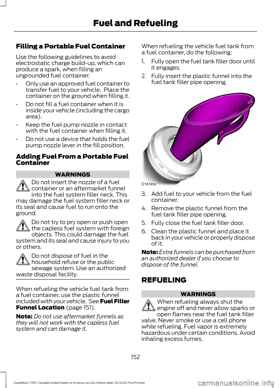
waste disposal facility. When refueling the vehicle fuel tank from
a fuel container, use the plastic funnel
included with your vehicle. See Fuel Filler
Funnel Location (page 151).
Note: Do not use aftermarket funnels as
they will not work with the capless fuel
system and can damage it. When refueling the vehicle fuel tank from
a fuel container, do the following:
1.
Fully open the fuel tank filler door until
it engages.
2. Fully insert the plastic funnel into the fuel tank filler pipe opening. 3. Add fuel to your vehicle from the fuel
container.
4. Remove the plastic funnel from the fuel tank filler pipe opening.
5. Fully close the fuel tank filler door.
6. Clean the plastic funnel and place it back in your vehicle or properly dispose
of it.
Note: Extra funnels can be purchased from
an authorized dealer if you choose to
dispose of the funnel.
REFUELING WARNINGS
When refueling always shut the
engine off and never allow sparks or
open flames near the fuel tank filler
valve. Never smoke or use a cell phone
while refueling. Fuel vapor is extremely
hazardous under certain conditions. Avoid
inhaling excess fumes.
152
Expedition (TB7) Canada/United States of America, enUSA, Edition date: 03/2016, First Printing Fuel and RefuelingE157452
Page 165 of 500
Manual (M)
Moving the gearshift lever to the manual
(M) position will allow you to manually
select the gear you desire. Only the current
gear will display. Use the buttons on the
gearshift lever to manually select gears.
Press the + button to upshift or the –
button to downshift. Return the
transmission to a different gearshift
position to deactivate manual control.
Upshift to the recommended shift speeds
according to the following chart:Upshifts when accelerating (recommended for best fuel economy)
Shift from:15 mph (24 km/h)
1 – 2
25 mph (40 km/h)
2 – 3
40 mph (64 km/h)
3 – 4
45 mph (72 km/h)
4 – 5
50 mph (80 km/h)
5 – 6
Brake-Shift Interlock WARNINGS
Do not drive your vehicle until you
verify that the brake lamps are
working.
When doing this procedure, you need
to take the transmission out of park
(P) which means your vehicle can
roll freely. To avoid unwanted vehicle
movement, always fully set the parking
brake prior to doing this procedure. Use
wheels chocks if appropriate. If the parking brake is fully released,
but the brake warning lamp remains
illuminated, the brakes may not be
working properly. Have your vehicle
checked as soon as possible. Your vehicle is equipped with a brake-shift
interlock feature that prevents moving the
gearshift lever from park (P) when the
ignition is in the on position and the brake
pedal is not pressed. If you cannot move the gearshift lever out
of park (P) position with the ignition in the
on position and the brake pedal pressed,
a malfunction may have occurred. It is
possible that a fuse has blown or your
vehicle
’s brake lamps are not operating
properly. See Fuse Specification Chart
(page 233).
If the fuse is not blown and the brake
lamps are working properly, the following
procedure will allow you to move the
gearshift lever from park (P):
Column-shifter
1. Apply the parking brake. Turn the ignition key to the off position, then
remove the key.
2. Move the steering column to the full down and full rearward position
(toward the driver ’s seat).
3. Remove the gearshift lever boot.
162
Expedition (TB7) Canada/United States of America, enUSA, Edition date: 03/2016, First Printing Transmission
Page 206 of 500
TOWING A TRAILER
WARNING
Towing trailers beyond the
maximum recommended
gross trailer weight exceeds the
limit of your vehicle and could
result in engine damage,
transmission damage, structural
damage, loss of vehicle control,
vehicle rollover and personal
injury. Note:
Do not exceed the GVWR or
the GAWR specified on the
certification label. See
Recommended Towing Weights
(page
204).
Your vehicle may have electrical
items, such as fuses or relays,
related to towing. See
Fuses
(page 233).
Your vehicle's load capacity
designation is by weight, not by
volume, so you cannot necessarily
use all available space when
loading a vehicle or trailer.
Towing a trailer places an extra
load on your vehicle's engine,
transmission, axle, brakes, tires
and suspension. Inspect these
components periodically during,
and after, any towing operation. Load Placement
To help minimize how trailer
movement affects your vehicle
when driving:
•
Load the heaviest items closest
to the trailer floor.
• Load the heaviest items
centered between the left and
right side trailer tires.
• Load the heaviest items above
the trailer axles or just slightly
forward toward the trailer
tongue. Do not allow the final
trailer tongue weight to go
above or below 10-15% of the
loaded trailer weight.
• Select a ball mount with the
correct rise or drop. When both
the loaded vehicle and trailer
are connected, the trailer frame
should be level, or slightly
angled down toward your
vehicle, when viewed from the
side.
When driving with a trailer or
payload, a slight takeoff vibration
or shudder may be present due to
the increased payload weight.
Additional information regarding
proper trailer loading and setting
your vehicle up for towing is
located in another chapter of this
manual. See
Load Limit (page
198).
You can also find information in
the
RV & Trailer Towing Guide
available at your authorized
dealer, or online.
203
Expedition (TB7) Canada/United States of America, enUSA, Edition date: 03/2016, First Printing Towing
Page 226 of 500
Note:
When you try to restart your vehicle
after a fuel shutoff, the vehicle makes sure
that various systems are safe to restart.
Once your vehicle determines that the
systems are safe, then the vehicle will allow
you to restart.
Note: In the event that your vehicle does
not restart after your third attempt, contact
an authorized dealer.
JUMP STARTING THE VEHICLE WARNINGS
Batteries normally produce explosive
gases which can cause personal
injury. Therefore, do not allow
flames, sparks or lighted substances to
come near the battery. When working near
the battery, always shield your face and
protect your eyes. Always provide correct
ventilation. Keep batteries out of reach of
children. Batteries contain sulfuric
acid. Avoid contact with skin, eyes or
clothing. Shield your eyes when working
near the battery to protect against possible
splashing of acid solution. In case of acid
contact with skin or eyes, flush
immediately with water for a minimum of
15 minutes and get prompt medical
attention. If acid is swallowed, call a
physician immediately. Use only adequately sized cables
with insulated clamps.
Preparing Your Vehicle
Do not attempt to push-start your
automatic transmission vehicle.
Note:
Attempting to push-start a vehicle
with an automatic transmission may cause
transmission damage.
Note: Use only a 12-volt supply to start your
vehicle. Note:
Do not disconnect the battery of the
disabled vehicle as this could damage the
vehicle electrical system.
Park the booster vehicle close to the hood
of the disabled vehicle, making sure the
two vehicles do not touch.
Connecting the Jumper Cables WARNINGS
Do not attach the cables to fuel lines,
engine rocker covers, the intake
manifold or electrical components
as grounding points. Stay clear of moving
parts. To avoid reverse polarity
connections, make sure that you correctly
identify the positive (+) and negative (-)
terminals on both the disabled and booster
vehicles before connecting the cables. Do not attach the end of the positive
cable to the studs or L-shaped eyelet
located above the positive (+)
terminal of your vehicle ’s battery. High
current may flow through and cause
damage to the fuses. Do not connect the end of the
second cable to the negative (-)
terminal of the battery to be jumped.
A spark may cause an explosion of the
gases that surround the battery. Note:
In the illustration, the bottom vehicle
represents the booster vehicle.
223
Expedition (TB7) Canada/United States of America, enUSA, Edition date: 03/2016, First Printing Roadside Emergencies
Page 236 of 500
FUSE SPECIFICATION CHART
Power Distribution Box
WARNINGS
Always disconnect the battery before
servicing high current fuses.
To reduce risk of electrical shock,
always replace the cover to the
power distribution box before
reconnecting the battery or refilling fluid
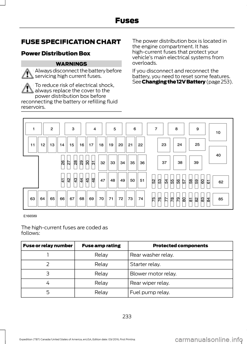
reservoirs. The power distribution box is located in
the engine compartment. It has
high-current fuses that protect your
vehicle
’s main electrical systems from
overloads.
If you disconnect and reconnect the
battery, you need to reset some features.
See Changing the 12V Battery (page 253). The high-current fuses are coded as
follows:
Protected components
Fuse amp rating
Fuse or relay number
Rear washer relay.
Relay
1
Starter relay.
Relay
2
Blower motor relay.
Relay
3
Rear wiper relay.
Relay
4
Fuel pump relay.
Relay
5
233
Expedition (TB7) Canada/United States of America, enUSA, Edition date: 03/2016, First Printing FusesE166589