ABS FORD EXPEDITION EL 2016 Owners Manual
[x] Cancel search | Manufacturer: FORD, Model Year: 2016, Model line: EXPEDITION EL, Model: FORD EXPEDITION EL 2016Pages: 421, PDF Size: 7.39 MB
Page 91 of 421
WARNING LAMPS AND
INDICATORS
The following warning lamps andindicators alert you to a vehicle conditionthat may become serious. Some lampsilluminate when you start your vehicle tomake sure they work. If any lamps remainon after starting your vehicle, refer to therespective system warning lamp for furtherinformation.
Note:Some warning indicators appear inthe information display and function thesame as a warning lamp but do not displaywhen you start your vehicle.
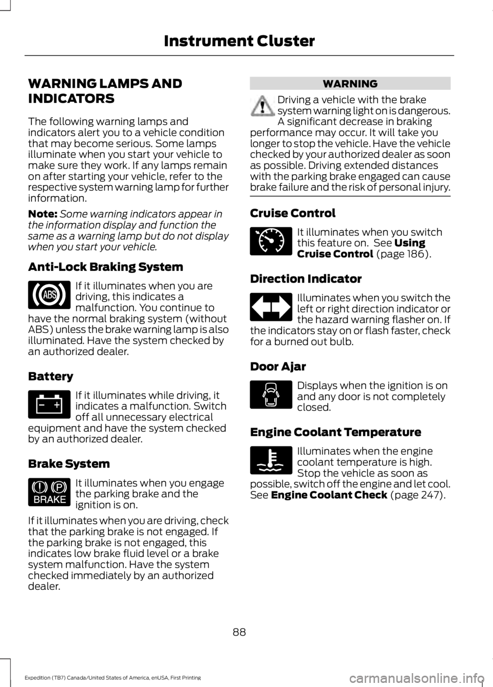
Anti-Lock Braking System
If it illuminates when you aredriving, this indicates amalfunction. You continue tohave the normal braking system (withoutABS) unless the brake warning lamp is alsoilluminated. Have the system checked byan authorized dealer.
Battery
If it illuminates while driving, itindicates a malfunction. Switchoff all unnecessary electricalequipment and have the system checkedby an authorized dealer.
Brake System
It illuminates when you engagethe parking brake and theignition is on.
If it illuminates when you are driving, checkthat the parking brake is not engaged. Ifthe parking brake is not engaged, thisindicates low brake fluid level or a brakesystem malfunction. Have the systemchecked immediately by an authorizeddealer.
WARNING
Driving a vehicle with the brakesystem warning light on is dangerous.A significant decrease in brakingperformance may occur. It will take youlonger to stop the vehicle. Have the vehiclechecked by your authorized dealer as soonas possible. Driving extended distanceswith the parking brake engaged can causebrake failure and the risk of personal injury.
Cruise Control
It illuminates when you switchthis feature on. See UsingCruise Control (page 186).
Direction Indicator
Illuminates when you switch theleft or right direction indicator orthe hazard warning flasher on. Ifthe indicators stay on or flash faster, checkfor a burned out bulb.
Door Ajar
Displays when the ignition is onand any door is not completelyclosed.
Engine Coolant Temperature
Illuminates when the enginecoolant temperature is high.Stop the vehicle as soon aspossible, switch off the engine and let cool.See Engine Coolant Check (page 247).
88
Expedition (TB7) Canada/United States of America, enUSA, First Printing
Instrument Cluster E144522 E71340
Page 126 of 421
WARNINGS
Install the head restraint properly tohelp minimize the risk of neck injuryin the event of a crash.
Note:Adjust the seatback to an uprightdriving position before adjusting the headrestraint. Adjust the head restraint so thatthe top of it is level with the top of your headand as far forward as possible. Make surethat you remain comfortable. If you areextremely tall, adjust the head restraint toits highest position.
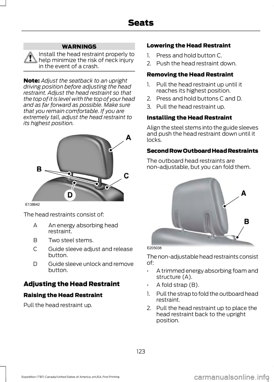
The head restraints consist of:
An energy absorbing headrestraint.A
Two steel stems.B
Guide sleeve adjust and releasebutton.C
Guide sleeve unlock and removebutton.D
Adjusting the Head Restraint
Raising the Head Restraint
Pull the head restraint up.
Lowering the Head Restraint
1. Press and hold button C.
2. Push the head restraint down.
Removing the Head Restraint
1. Pull the head restraint up until itreaches its highest position.
2. Press and hold buttons C and D.
3. Pull the head restraint up.
Installing the Head Restraint
Align the steel stems into the guide sleevesand push the head restraint down until itlocks.
Second Row Outboard Head Restraints
The outboard head restraints arenon-adjustable, but you can fold them.
The non-adjustable head restraints consistof:
•A trimmed energy absorbing foam andstructure (A).
•A fold strap (B).
1.Pull the strap to fold the outboard headrestraint.
2. Pull the head restraint up to place thehead restraint back to the uprightposition.
123
Expedition (TB7) Canada/United States of America, enUSA, First Printing
SeatsE138642 E205038
Page 127 of 421
Second Row Center Seat HeadRestraint
The center rear head restraint is fixed andnon-adjustable. The head restraintconsists of a trimmed foam covering overthe upper structure of the seatback.
Third Row Head Restraints
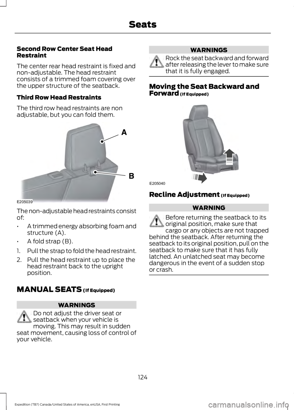
The third row head restraints are nonadjustable, but you can fold them.
The non-adjustable head restraints consistof:
•A trimmed energy absorbing foam andstructure (A).
•A fold strap (B).
1.Pull the strap to fold the head restraint.
2. Pull the head restraint up to place thehead restraint back to the uprightposition.
MANUAL SEATS (If Equipped)
WARNINGS
Do not adjust the driver seat orseatback when your vehicle ismoving. This may result in suddenseat movement, causing loss of control ofyour vehicle.
WARNINGS
Rock the seat backward and forwardafter releasing the lever to make surethat it is fully engaged.
Moving the Seat Backward andForward (If Equipped)
Recline Adjustment (If Equipped)
WARNING
Before returning the seatback to itsoriginal position, make sure thatcargo or any objects are not trappedbehind the seatback. After returning theseatback to its original position, pull on theseatback to make sure that it has fullylatched. An unlatched seat may becomedangerous in the event of a sudden stopor crash.
124
Expedition (TB7) Canada/United States of America, enUSA, First Printing
SeatsE205039 E205040
Page 139 of 421
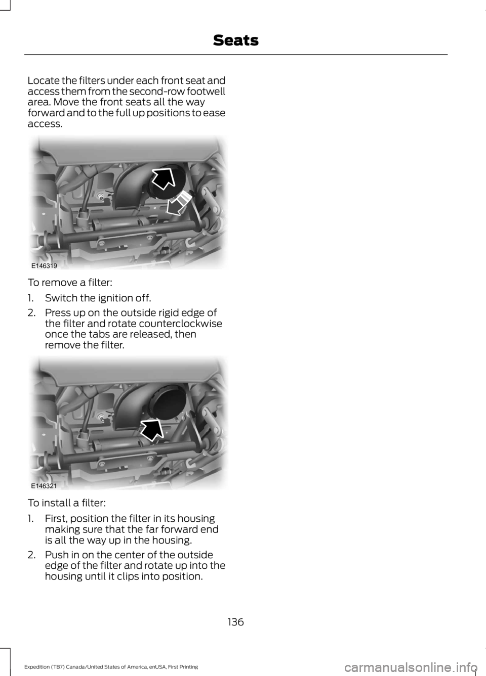
Locate the filters under each front seat andaccess them from the second-row footwellarea. Move the front seats all the wayforward and to the full up positions to easeaccess.
To remove a filter:
1. Switch the ignition off.
2. Press up on the outside rigid edge ofthe filter and rotate counterclockwiseonce the tabs are released, thenremove the filter.
To install a filter:
1. First, position the filter in its housingmaking sure that the far forward endis all the way up in the housing.
2. Push in on the center of the outsideedge of the filter and rotate up into thehousing until it clips into position.
136
Expedition (TB7) Canada/United States of America, enUSA, First Printing
SeatsE146319 E146321
Page 154 of 421
SAFETY PRECAUTIONS
WARNINGS
Do not overfill the fuel tank. Thepressure in an overfilled tank maycause leakage and lead to fuel sprayand fire.
The fuel system may be underpressure. If you hear a hissing soundnear the fuel filler door (Easy Fuelcapless fuel system), do not refuel untilthe sound stops. Otherwise, fuel may sprayout, which could cause serious personalinjury.
Automotive fuels can cause seriousinjury or death if misused ormishandled.
Flow of fuel through a fuel pumpnozzle can produce static electricity.This can cause a fire if you are fillingan ungrounded fuel container.
Fuel ethanol and gasoline maycontain benzene, which is acancer-causing agent.
When refueling always shut theengine off and never allow sparks oropen flames near the filler neck.Never smoke or use a cell phone whilerefueling. Fuel vapor is extremelyhazardous under certain conditions. Avoidinhaling excess fumes.
Observe the following guidelines whenhandling automotive fuel:
•Extinguish all smoking materials andany open flames before refueling yourvehicle.
•Always turn off the vehicle beforerefueling.
•Automotive fuels can be harmful orfatal if swallowed. Fuel such asgasoline is highly toxic and ifswallowed can cause death orpermanent injury. If fuel is swallowed,call a physician immediately, even if nosymptoms are immediately apparent.The toxic effects of fuel may not bevisible for hours.
•Avoid inhaling fuel vapors. Inhaling toomuch fuel vapor of any kind can leadto eye and respiratory tract irritation.In severe cases, excessive or prolongedbreathing of fuel vapor can causeserious illness and permanent injury.
•Avoid getting fuel liquid in your eyes. Iffuel is splashed in the eyes, removecontact lenses (if worn), flush withwater for 15 minutes and seek medicalattention. Failure to seek propermedical attention could lead topermanent injury.
•Fuels can also be harmful if absorbedthrough the skin. If fuel is splashed onthe skin, clothing or both, promptlyremove contaminated clothing andwash skin thoroughly with soap andwater. Repeated or prolonged skincontact with fuel liquid or vapor causesskin irritation.
•Be particularly careful if you are taking“Antabuse” or other forms of disulfiramfor the treatment of alcoholism.Breathing gasoline vapors, or skincontact could cause an adversereaction. In sensitive individuals, seriouspersonal injury or sickness may result.If fuel is splashed on the skin, promptlywash skin thoroughly with soap andwater. Consult a physician immediatelyif you experience an adverse reaction.
151
Expedition (TB7) Canada/United States of America, enUSA, First Printing
Fuel and Refueling
Page 182 of 421
USING HILL DESCENT
CONTROL
Principle of Operation
WARNINGS
Hill descent control cannot controldescent in all surface conditions andcircumstances, such as ice orextremely steep grades. Hill descentcontrol is a driver assist system and cannotsubstitute for good judgment by the driver.Failure to do so may result in loss of vehiclecontrol, crash or serious injury.
Hill descent control does not providehill hold at 0 mph (0 km/h). Whenstopped, the parking brake must beapplied or the vehicle must be placed inpark (P) or it may roll away.
Hill descent control allows the driver to setand maintain vehicle speed whiledescending steep grades in various surfaceconditions.
Hill descent control can maintain vehiclespeeds on downhill grades between 3 mph(5 km/h) and 20 mph (32 km/h). Above20 mph (32 km/h), the system remainsarmed, but descent speed cannot be setor maintained.
Hill descent control requires a coolingdown interval after sustained use. Theamount of time that the feature canremain active before cooling varies withconditions. The system provides a warningin the message center and a chime soundswhen the system is about to disengage forcooling. At this time, manually apply thebrakes to maintain descent speed.
Using Hill Descent Control
Press and release the hilldescent button in the center ofthe terrain management control.The button illuminates and a chime soundswhen you switch this feature on.
To increase descent speed, press theaccelerator pedal until you reach thedesired speed. To decrease descentspeed, press the brake pedal until youreach the desired speed.
Whether accelerating or decelerating, onceyou reach the desired descent speed,remove your feet from the pedals and hilldescent control maintains the chosenvehicle speed.
Note:You may observe noise from the ABSpump motor during hill descent controloperation. This is a normal characteristic ofthe ABS and should be no reason forconcern.
179
Expedition (TB7) Canada/United States of America, enUSA, First Printing
Terrain Response (If Equipped)
Page 184 of 421
PRINCIPLE OF OPERATION
WARNINGS
To help avoid personal injury, pleaseread and understand the limitationsof the system as contained in thissection. Sensing is only an aid for some(generally large and fixed) objects whenmoving on a flat surface at parking speeds.Certain objects with surfaces that absorbultrasonic waves, surrounding vehicle'sparking aid systems, traffic controlsystems, fluorescent lamps, inclementweather, air brakes, and external motorsand fans may also affect the function ofthe sensing system; this may includereduced performance or a false activation.
To help avoid personal injury, alwaysuse caution when in reverse (R) andwhen using the sensing system.
This system is not designed toprevent contact with small or movingobjects. The system is designed toprovide a warning to assist the driver indetecting large stationary objects to avoiddamaging your vehicle. The system maynot detect smaller objects, particularlythose close to the ground.
Certain add-on devices such as largetrailer hitches, bike or surfboard racksand any device that may block thenormal detection zone of the system, maycreate false beeps.
Note:Keep the sensors, located on thebumper or fascia, free from snow, ice andlarge accumulations of dirt. If the sensorsare covered, the system’s accuracy can beaffected. Do not clean the sensors withsharp objects.
Note:If your vehicle sustains damage tothe bumper or fascia, leaving it misalignedor bent, the sensing zone may be alteredcausing inaccurate measurement ofobstacles or false alarms.
Note:The sensing system cannot be turnedoff when a MyKey is present. See Principleof Operation (page 46).
Note:If you attach certain add-on devicessuch as a trailer or bike rack, the rear sensingsystem may detect that add-on device andtherefore provide warnings. It is suggestedthat you disable the rear sensing systemwhen you attach an add-on device to yourvehicle to prevent these warnings.
The sensing system warns the driver ofobstacles within a certain range of yourvehicle. The system turns on automaticallywhenever you switch the ignition on.
The system can be switched off throughthe information display menu or from thepop-up message that appears once youshift the transmission into reverse (R). SeeGeneral Information (page 92).
Note:On vehicles with front parking aid youcan use the parking aid switch to switch thesystem off.
If a fault is present in the system, a warningmessage appears in the informationdisplay. See Information Messages(page 103).
REAR PARKING AID
The rear sensors are only active when thetransmission is in reverse (R). As yourvehicle moves closer to the obstacle, therate of the audible warning increases.When the obstacle is less than 10 in(25 cm) away, the warning soundscontinuously. If the system detects astationary or receding object farther than10 in (25 cm) from the corners of thebumper, the tone sounds for only threeseconds. Once the system detects anobject approaching, the warning soundsagain.
181
Expedition (TB7) Canada/United States of America, enUSA, First Printing
Parking Aids
Page 197 of 421
Extreme continuous steering may increasethe effort required for you to steer yourvehicle. This increased effort preventsoverheating and permanent damage tothe steering system. You do not lose theability to steer your vehicle manually.Typical steering and driving maneuversallow the system to cool and return tonormal operation.
Steering Tips
If the steering wanders or pulls, check for:
•Correct tire pressures.
•Uneven tire wear.
•Loose or worn suspensioncomponents.
•Loose or worn steering components.
•Improper vehicle alignment.
Note:A high crown in the road or highcrosswinds may also make the steeringseem to wander or pull.
Adaptive Learning
The electronic power steering systemadaptive learning helps correct roadirregularities and improves overall handlingand steering feel. It communicates withthe brake system to help operateadvanced stability control and accidentavoidance systems. Additionally, wheneverthe battery is disconnected or a newbattery installed, you must drive yourvehicle a short distance before the systemrelearns the strategy and reactivates allsystems.
DRIVE CONTROL
Driver Select Suspension
Driver select suspension delivers a uniquedriving experience through a suite ofsophisticated electronic vehicle systems.These systems continuously monitor yourdriving inputs and the road conditions tooptimize ride comfort, steering andhandling.
Driver select suspension consists of thefollowing systems:
•Continuously controlled dampingdynamically adjusts the shockabsorbers stiffness in real time tomatch the road surface and driverinputs. This system continuouslymonitors your vehicle’s motion (roll,pitch, bounce), suspension position,load, speed, road conditions, andsteering to adjust the suspensiondamping for optimal vehicle control.
•Electronically power-assisted steeringadjusts steering effort and feel basedon your vehicle speed and your inputs.
The configuration remains active untilmodified from the main menu on theinformation display. See GeneralInformation (page 92).
194
Expedition (TB7) Canada/United States of America, enUSA, First Printing
Driving Aids
Page 219 of 421
Before using recovery hooks:
•Make sure all attaching points aresecure and capable of withstandingthe applied load.
•Never use chains, cables or tow strapswith metal hook ends.
•Only use recovery straps that have aminimum breaking strength two tothree times the gross vehicle weight ofthe stuck vehicle.
•Make sure the recovery strap is in goodcondition and free of visible cuts, tearsor damage.
•Use a damper device such as a tarp,heavy blanket or piece of carpetdraped over the recovery strap to helpabsorb the energy in the event thestrap breaks.
•Make sure the stuck vehicle is notloaded heavier than its gross vehicleweight rating specified on thecertification label.
•Always align the tow vehicle and stuckvehicle in a straight line (within 10degrees).
•Keep bystanders to the sides of thevehicle, at a distance of at least twicethe length of the recovery strap. Thishelps avoid injury from the hazard of arecovery hook or strap breaking, or avehicle lurching into their path.
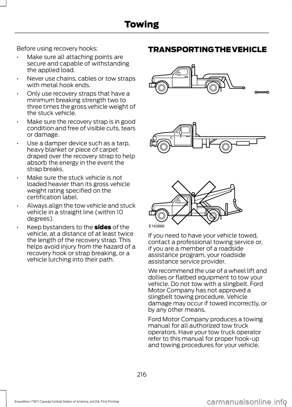
TRANSPORTING THE VEHICLE
If you need to have your vehicle towed,contact a professional towing service or,if you are a member of a roadsideassistance program, your roadsideassistance service provider.
We recommend the use of a wheel lift anddollies or flatbed equipment to tow yourvehicle. Do not tow with a slingbelt. FordMotor Company has not approved aslingbelt towing procedure. Vehicledamage may occur if towed incorrectly, orby any other means.
Ford Motor Company produces a towingmanual for all authorized tow truckoperators. Have your tow truck operatorrefer to this manual for proper hook-upand towing procedures for your vehicle.
216
Expedition (TB7) Canada/United States of America, enUSA, First Printing
TowingE143886
Page 241 of 421
Protected componentsFuse amp ratingFuse or relay number
Not used.—81
Rain sensor.5A**82
Not used.—83
Not used.—84
Wiper motor relay.Relay85
*Cartridge fuses.
**Mini fuses.
Passenger Compartment FusePanel
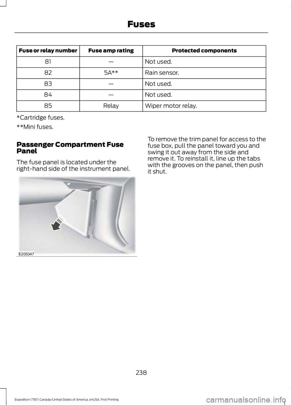
The fuse panel is located under theright-hand side of the instrument panel.
To remove the trim panel for access to thefuse box, pull the panel toward you andswing it out away from the side andremove it. To reinstall it, line up the tabswith the grooves on the panel, then pushit shut.
238
Expedition (TB7) Canada/United States of America, enUSA, First Printing
FusesE205347