fuses FORD EXPEDITION EL 2016 Owners Manual
[x] Cancel search | Manufacturer: FORD, Model Year: 2016, Model line: EXPEDITION EL, Model: FORD EXPEDITION EL 2016Pages: 421, PDF Size: 7.39 MB
Page 7 of 421
Economical Driving.....................................220
Driving Through Water................................221
Floor Mats........................................................221
Roadside Emergencies
Roadside Assistance..................................223
Hazard Warning Flashers..........................224
Fuel Shutoff...................................................224
Jump Starting the Vehicle........................225
Customer Assistance
Getting the Services You Need...............228
In California (U.S. Only).............................229
The Better Business Bureau (BBB) AutoLine Program (U.S. Only).....................230
Utilizing the Mediation/ArbitrationProgram (Canada Only).......................230
Getting Assistance Outside the U.S. andCanada.........................................................231
Ordering Additional Owner'sLiterature.....................................................232
Reporting Safety Defects (U.S.Only).............................................................232
Reporting Safety Defects (CanadaOnly).............................................................233
Fuses
Fuse Specification Chart..........................234
Changing a Fuse...........................................242
Maintenance
General Information...................................243
Opening and Closing the Hood..............243
Under Hood Overview - 3.5LEcoboost™................................................244
Engine Oil Dipstick......................................245
Engine Oil Check..........................................245
Oil Change Indicator Reset......................246
Engine Coolant Check................................247
Automatic Transmission FluidCheck...........................................................250
Transfer Case Fluid Check.........................251
Brake Fluid Check.........................................251
Washer Fluid Check....................................252
Fuel Filter........................................................252
Changing the 12V Battery.........................252
Checking the Wiper Blades.....................254
Changing the Wiper Blades.....................255
Adjusting the Headlamps.........................255
Removing a Headlamp..............................256
Changing a Bulb...........................................257
Bulb Specification Chart..........................260
Changing the Engine Air Filter.................262
Vehicle Care
General Information...................................264
Cleaning Products.......................................264
Cleaning the Exterior..................................264
Waxing.............................................................265
Cleaning the Engine....................................265
Cleaning the Windows and WiperBlades..........................................................266
Cleaning the Interior...................................266
Cleaning the Instrument Panel andInstrument Cluster Lens........................267
Cleaning Leather Seats.............................267
Repairing Minor Paint Damage..............269
Cleaning the Alloy Wheels.......................269
Vehicle Storage............................................269
Wheels and Tires
General Information....................................272
Tire Care..........................................................275
Using Snow Chains....................................290
Tire Pressure Monitoring System..........290
Changing a Road Wheel...........................296
Technical Specifications............................301
Capacities and Specific-ations
Engine Specifications................................303
4
Expedition (TB7) Canada/United States of America, enUSA, First Printing
Table of Contents
Page 38 of 421
PRINCIPLE OF OPERATION
WARNINGS
Airbags do not inflate slowly orgently, and the risk of injury from adeploying airbag is the greatest closeto the trim covering the airbag module.
All occupants of your vehicle,including the driver, should alwaysproperly wear their safety belts, evenwhen an airbag supplemental restraintsystem is provided. Failure to properly wearyour safety belt could seriously increasethe risk of injury or death.
Always transport children 12 yearsold and under in the back seat andalways properly use appropriatechild restraints. Failure to follow this couldseriously increase the risk of injury or death.
Never place your arm over the airbagmodule as a deploying airbag canresult in serious arm fractures orother injuries.
Airbags can kill or injure a child in achild seat. Never place a rear-facingchild seat in front of an active airbag.If you must use a forward-facing child seatin the front seat, move the seat upon whichthe child seat is installed all the way back.
Do not attempt to service, repair, ormodify the airbag supplementalrestraint systems or its fuses as youcould be seriously injured or killed. Contactyour authorized dealer as soon as possible.
Several airbag system componentsget hot after inflation. To avoid riskof injury, do not touch them afterinflation.
If the airbag has deployed, the airbagwill not function again and must bereplaced immediately. If the airbagis not replaced, the unrepaired area willincrease the risk of injury in a crash.
The airbags are a supplemental restraintsystem and are designed to work with thesafety belts to help protect the driver andright front passenger from certain upperbody injuries. Airbags do not inflate slowly;there is a risk of injury from a deployingairbag.
Note:You will hear a loud bang and see acloud of harmless powdery residue if anairbag deploys. This is normal.
The airbags inflate and deflate rapidlyupon activation. After airbag deployment,it is normal to notice a smoke-like, powderyresidue or smell the burnt propellant. Thismay consist of cornstarch, talcum powder(to lubricate the bag) or sodiumcompounds (for example, baking soda)that result from the combustion processthat inflates the airbag. Small amounts ofsodium hydroxide may be present whichmay irritate the skin and eyes, but none ofthe residue is toxic.
While the system is designed to helpreduce serious injuries, contact with adeploying airbag may also cause abrasionsor swelling. Temporary hearing loss is alsoa possibility as a result of the noiseassociated with a deploying airbag.Because airbags must inflate rapidly andwith considerable force, there is the risk ofdeath or serious injuries such as fractures,facial and eye injuries or internal injuries,particularly to occupants who are notproperly restrained or are otherwise out ofposition at the time of airbag deployment.Thus, it is extremely important thatoccupants be properly restrained as faraway from the airbag module as possiblewhile maintaining vehicle control.
Routine maintenance of the airbags is notrequired.
35
Expedition (TB7) Canada/United States of America, enUSA, First Printing
Supplementary Restraints System
Page 41 of 421
WARNINGS
Do not attempt to service, repair, ormodify the airbag, its fuses or theseat cover on a seat containing anairbag as you could be seriously injured orkilled. Contact your authorized dealer assoon as possible.
If the side airbag has deployed, theairbag will not function again. Theside airbag system (including theseat) must be inspected and serviced byan authorized dealer. If the airbag is notreplaced, the unrepaired area will increasethe risk of injury in a crash.
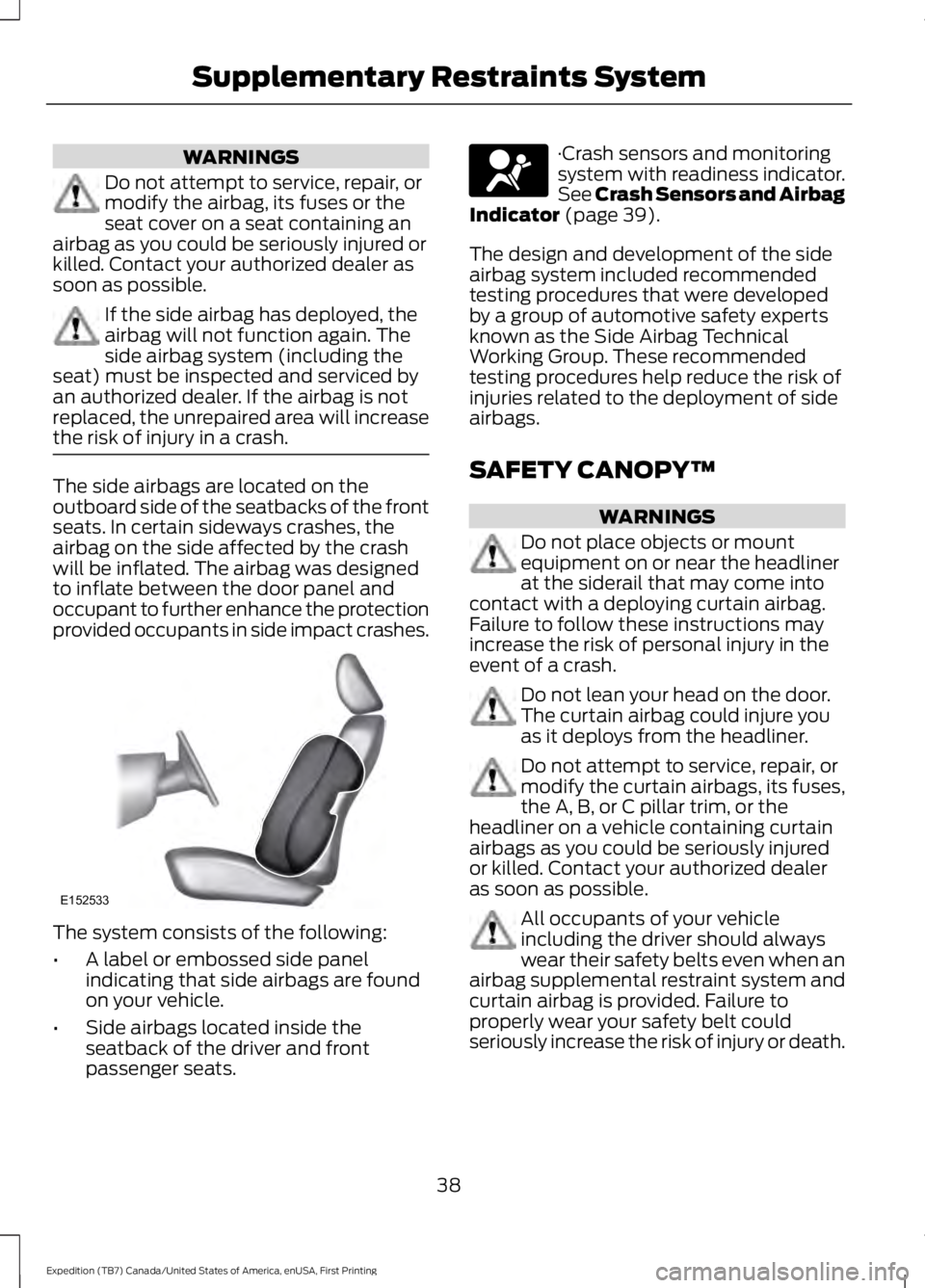
The side airbags are located on theoutboard side of the seatbacks of the frontseats. In certain sideways crashes, theairbag on the side affected by the crashwill be inflated. The airbag was designedto inflate between the door panel andoccupant to further enhance the protectionprovided occupants in side impact crashes.
The system consists of the following:
•A label or embossed side panelindicating that side airbags are foundon your vehicle.
•Side airbags located inside theseatback of the driver and frontpassenger seats.
·Crash sensors and monitoringsystem with readiness indicator.See Crash Sensors and AirbagIndicator (page 39).
The design and development of the sideairbag system included recommendedtesting procedures that were developedby a group of automotive safety expertsknown as the Side Airbag TechnicalWorking Group. These recommendedtesting procedures help reduce the risk ofinjuries related to the deployment of sideairbags.
SAFETY CANOPY™
WARNINGS
Do not place objects or mountequipment on or near the headlinerat the siderail that may come intocontact with a deploying curtain airbag.Failure to follow these instructions mayincrease the risk of personal injury in theevent of a crash.
Do not lean your head on the door.The curtain airbag could injure youas it deploys from the headliner.
Do not attempt to service, repair, ormodify the curtain airbags, its fuses,the A, B, or C pillar trim, or theheadliner on a vehicle containing curtainairbags as you could be seriously injuredor killed. Contact your authorized dealeras soon as possible.
All occupants of your vehicleincluding the driver should alwayswear their safety belts even when anairbag supplemental restraint system andcurtain airbag is provided. Failure toproperly wear your safety belt couldseriously increase the risk of injury or death.
38
Expedition (TB7) Canada/United States of America, enUSA, First Printing
Supplementary Restraints SystemE152533
Page 208 of 421
TOWING A TRAILER
WARNINGS
Do not exceed the GVWR orthe GAWR specified on thecertification label.
Towing trailers beyond themaximum recommendedgross trailer weight exceeds thelimit of the vehicle and couldresult in engine damage,transmission damage, structuraldamage, loss of vehicle control,vehicle rollover and personalinjury.
Your vehicle may have electricalitems, such as fuses or relays,related to towing. See the Fuseschapter.
Your vehicle's load capacitydesignation is by weight, not byvolume, so you cannot necessarilyuse all available space whenloading a vehicle or trailer.
Towing a trailer places an extraload on your vehicle's engine,transmission, axle, brakes, tiresand suspension. Inspect thesecomponents periodically during,and after, any towing operation.
Load Placement
To help minimize how trailermovement affects your vehiclewhen driving:
•Load the heaviest items closestto the trailer floor.
•Load the heaviest itemscentered between the left andright side trailer tires.
•Load the heaviest items abovethe trailer axles or just slightlyforward toward the trailertongue. Do not allow the finaltrailer tongue weight to goabove or below 10-15% of theloaded trailer weight.
•Select a tow bar with thecorrect rise or drop. When boththe loaded vehicle and trailerare connected, the trailer frameshould be level, or slightlyangled down toward yourvehicle, when viewed from theside.
When driving with a trailer orpayload, a slight takeoff vibrationor shudder may be present due tothe increased payload weight.Additional information regardingproper trailer loading and settingyour vehicle up for towing islocated in another chapter of thismanual. See Load Limit (page198).
You can also find information inthe RV & Trailer Towing Guideavailable at your authorizeddealer, or online.
205
Expedition (TB7) Canada/United States of America, enUSA, First Printing
Towing
Page 228 of 421
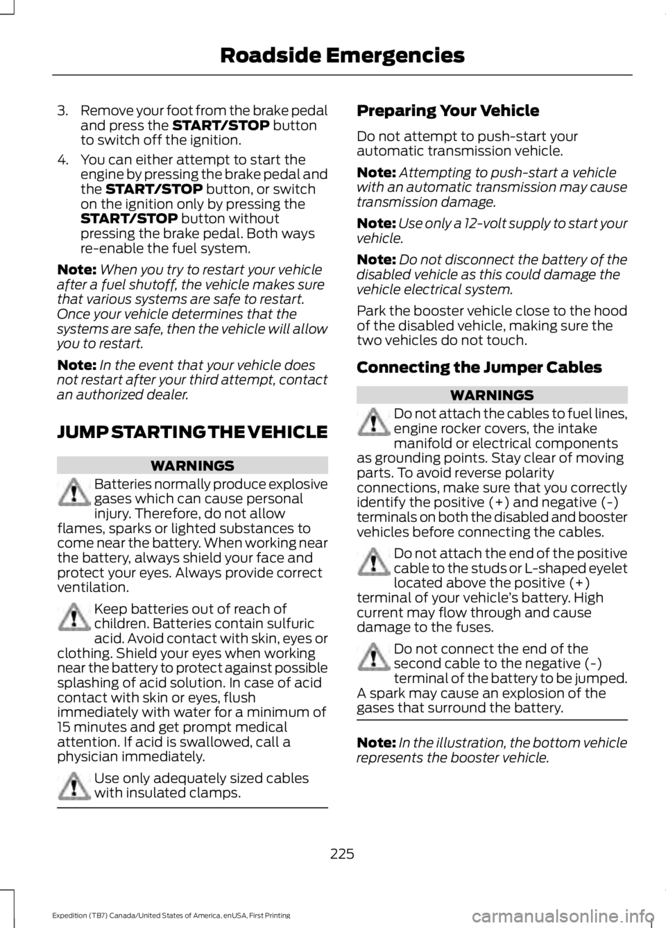
3.Remove your foot from the brake pedaland press the START/STOP buttonto switch off the ignition.
4. You can either attempt to start theengine by pressing the brake pedal andthe START/STOP button, or switchon the ignition only by pressing theSTART/STOP button withoutpressing the brake pedal. Both waysre-enable the fuel system.
Note:When you try to restart your vehicleafter a fuel shutoff, the vehicle makes surethat various systems are safe to restart.Once your vehicle determines that thesystems are safe, then the vehicle will allowyou to restart.
Note:In the event that your vehicle doesnot restart after your third attempt, contactan authorized dealer.
JUMP STARTING THE VEHICLE
WARNINGS
Batteries normally produce explosivegases which can cause personalinjury. Therefore, do not allowflames, sparks or lighted substances tocome near the battery. When working nearthe battery, always shield your face andprotect your eyes. Always provide correctventilation.
Keep batteries out of reach ofchildren. Batteries contain sulfuricacid. Avoid contact with skin, eyes orclothing. Shield your eyes when workingnear the battery to protect against possiblesplashing of acid solution. In case of acidcontact with skin or eyes, flushimmediately with water for a minimum of15 minutes and get prompt medicalattention. If acid is swallowed, call aphysician immediately.
Use only adequately sized cableswith insulated clamps.
Preparing Your Vehicle
Do not attempt to push-start yourautomatic transmission vehicle.
Note:Attempting to push-start a vehiclewith an automatic transmission may causetransmission damage.
Note:Use only a 12-volt supply to start yourvehicle.
Note:Do not disconnect the battery of thedisabled vehicle as this could damage thevehicle electrical system.
Park the booster vehicle close to the hoodof the disabled vehicle, making sure thetwo vehicles do not touch.
Connecting the Jumper Cables
WARNINGS
Do not attach the cables to fuel lines,engine rocker covers, the intakemanifold or electrical componentsas grounding points. Stay clear of movingparts. To avoid reverse polarityconnections, make sure that you correctlyidentify the positive (+) and negative (-)terminals on both the disabled and boostervehicles before connecting the cables.
Do not attach the end of the positivecable to the studs or L-shaped eyeletlocated above the positive (+)terminal of your vehicle’s battery. Highcurrent may flow through and causedamage to the fuses.
Do not connect the end of thesecond cable to the negative (-)terminal of the battery to be jumped.A spark may cause an explosion of thegases that surround the battery.
Note:In the illustration, the bottom vehiclerepresents the booster vehicle.
225
Expedition (TB7) Canada/United States of America, enUSA, First Printing
Roadside Emergencies
Page 237 of 421
FUSE SPECIFICATION CHART
Power Distribution Box
WARNINGS
Always disconnect the battery beforeservicing high current fuses.
To reduce risk of electrical shock,always replace the cover to thepower distribution box beforereconnecting the battery or refilling fluidreservoirs.
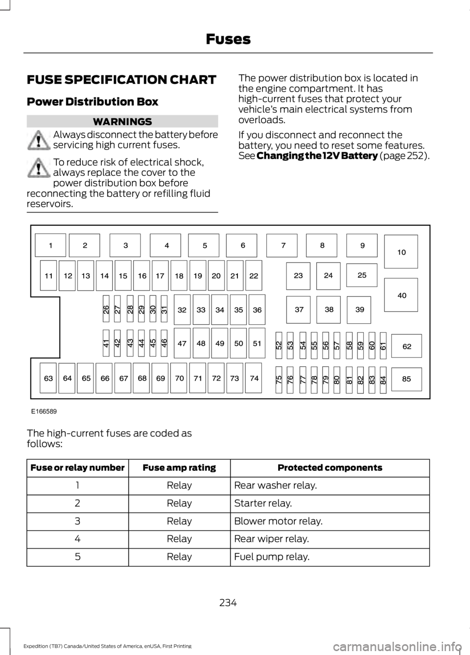
The power distribution box is located inthe engine compartment. It hashigh-current fuses that protect yourvehicle’s main electrical systems fromoverloads.
If you disconnect and reconnect thebattery, you need to reset some features.See Changing the 12V Battery (page 252).
The high-current fuses are coded asfollows:
Protected componentsFuse amp ratingFuse or relay number
Rear washer relay.Relay1
Starter relay.Relay2
Blower motor relay.Relay3
Rear wiper relay.Relay4
Fuel pump relay.Relay5
234
Expedition (TB7) Canada/United States of America, enUSA, First Printing
FusesE166589
Page 238 of 421
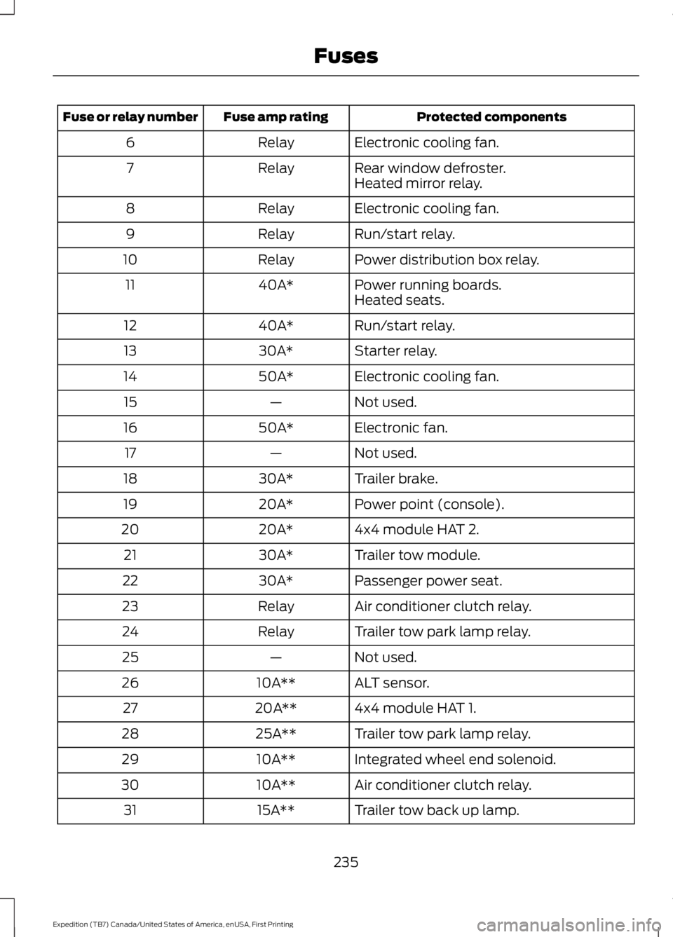
Protected componentsFuse amp ratingFuse or relay number
Electronic cooling fan.Relay6
Rear window defroster.Relay7Heated mirror relay.
Electronic cooling fan.Relay8
Run/start relay.Relay9
Power distribution box relay.Relay10
Power running boards.40A*11Heated seats.
Run/start relay.40A*12
Starter relay.30A*13
Electronic cooling fan.50A*14
Not used.—15
Electronic fan.50A*16
Not used.—17
Trailer brake.30A*18
Power point (console).20A*19
4x4 module HAT 2.20A*20
Trailer tow module.30A*21
Passenger power seat.30A*22
Air conditioner clutch relay.Relay23
Trailer tow park lamp relay.Relay24
Not used.—25
ALT sensor.10A**26
4x4 module HAT 1.20A**27
Trailer tow park lamp relay.25A**28
Integrated wheel end solenoid.10A**29
Air conditioner clutch relay.10A**30
Trailer tow back up lamp.15A**31
235
Expedition (TB7) Canada/United States of America, enUSA, First Printing
Fuses
Page 239 of 421
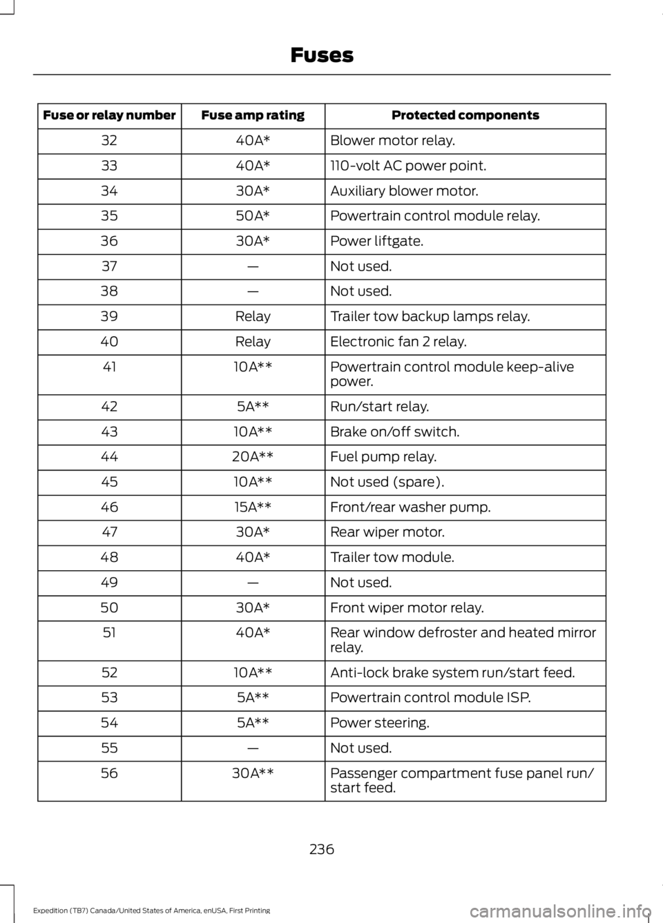
Protected componentsFuse amp ratingFuse or relay number
Blower motor relay.40A*32
110-volt AC power point.40A*33
Auxiliary blower motor.30A*34
Powertrain control module relay.50A*35
Power liftgate.30A*36
Not used.—37
Not used.—38
Trailer tow backup lamps relay.Relay39
Electronic fan 2 relay.Relay40
Powertrain control module keep-alivepower.10A**41
Run/start relay.5A**42
Brake on/off switch.10A**43
Fuel pump relay.20A**44
Not used (spare).10A**45
Front/rear washer pump.15A**46
Rear wiper motor.30A*47
Trailer tow module.40A*48
Not used.—49
Front wiper motor relay.30A*50
Rear window defroster and heated mirrorrelay.40A*51
Anti-lock brake system run/start feed.10A**52
Powertrain control module ISP.5A**53
Power steering.5A**54
Not used.—55
Passenger compartment fuse panel run/start feed.30A**56
236
Expedition (TB7) Canada/United States of America, enUSA, First Printing
Fuses
Page 240 of 421
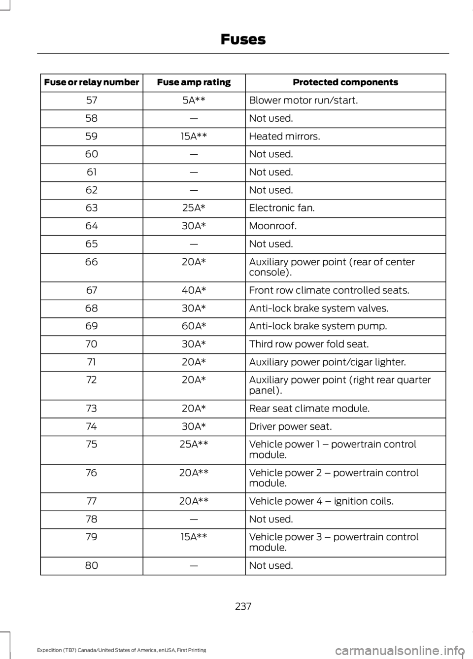
Protected componentsFuse amp ratingFuse or relay number
Blower motor run/start.5A**57
Not used.—58
Heated mirrors.15A**59
Not used.—60
Not used.—61
Not used.—62
Electronic fan.25A*63
Moonroof.30A*64
Not used.—65
Auxiliary power point (rear of centerconsole).20A*66
Front row climate controlled seats.40A*67
Anti-lock brake system valves.30A*68
Anti-lock brake system pump.60A*69
Third row power fold seat.30A*70
Auxiliary power point/cigar lighter.20A*71
Auxiliary power point (right rear quarterpanel).20A*72
Rear seat climate module.20A*73
Driver power seat.30A*74
Vehicle power 1 – powertrain controlmodule.25A**75
Vehicle power 2 – powertrain controlmodule.20A**76
Vehicle power 4 – ignition coils.20A**77
Not used.—78
Vehicle power 3 – powertrain controlmodule.15A**79
Not used.—80
237
Expedition (TB7) Canada/United States of America, enUSA, First Printing
Fuses
Page 241 of 421
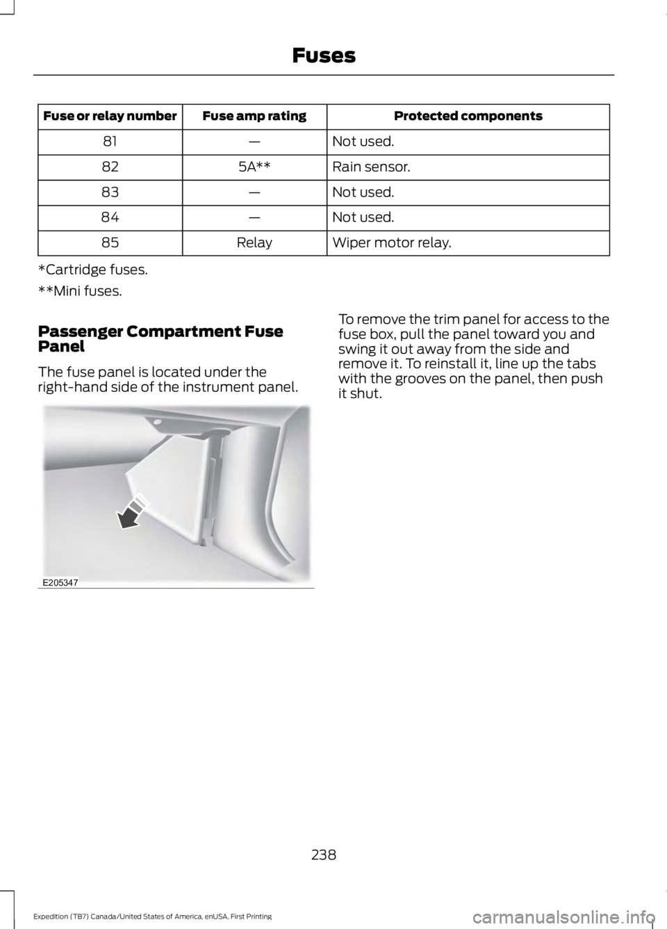
Protected componentsFuse amp ratingFuse or relay number
Not used.—81
Rain sensor.5A**82
Not used.—83
Not used.—84
Wiper motor relay.Relay85
*Cartridge fuses.
**Mini fuses.
Passenger Compartment FusePanel
The fuse panel is located under theright-hand side of the instrument panel.
To remove the trim panel for access to thefuse box, pull the panel toward you andswing it out away from the side andremove it. To reinstall it, line up the tabswith the grooves on the panel, then pushit shut.
238
Expedition (TB7) Canada/United States of America, enUSA, First Printing
FusesE205347