headlamp FORD EXPLORER 2015 5.G User Guide
[x] Cancel search | Manufacturer: FORD, Model Year: 2015, Model line: EXPLORER, Model: FORD EXPLORER 2015 5.GPages: 596, PDF Size: 6.32 MB
Page 191 of 596
Before starting the engine check the following:
•Make sure all occupants have fastened their safety belts.
•Make sure the headlamps and electrical accessories are off.
•Make sure the parking brake is on.
•Make sure the gearshift is in positionP.
•Turn the ignition key to the on position. If your vehicle is equipped
with a keyless ignition, see the following instructions.
Vehicles with an Ignition Key
Note:Do not touch the accelerator pedal.
1. Fully press the brake pedal.
2. Turn the key to the start position. Release the key when the engine
starts.
Note:The engine may continue cranking for up to 15 seconds or until it
starts.
Note:If you cannot start the engine on the first try, wait for a short
period and try again.
Vehicles with Keyless Start
Note:Do not touch the accelerator pedal.
1. Fully press the brake pedal.
2. Press the button.
The system does not function if:
•The key frequencies are jammed.
•The key battery has no charge.
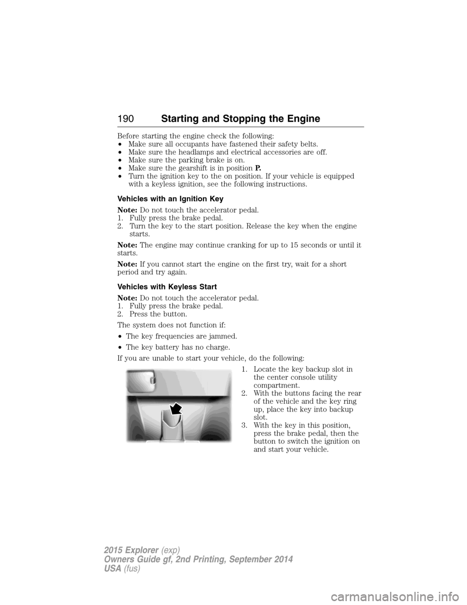
If you are unable to start your vehicle, do the following:
1. Locate the key backup slot in
the center console utility
compartment.
2. With the buttons facing the rear
of the vehicle and the key ring
up, place the key into backup
slot.
3. With the key in this position,
press the brake pedal, then the
button to switch the ignition on
and start your vehicle.
190Starting and Stopping the Engine
2015 Explorer(exp)
Owners Guide gf, 2nd Printing, September 2014
USA(fus)
Page 207 of 596
D (Drive) with Overdrive
The normal driving position for the best fuel economy. Transmission
operates in gears one through six.
The automatic transmission shift strategy has the ability to detect hilly
terrain or mountainous areas and will provide a limited amount of grade
assist features automatically. Refer toD(Drive) with Grade assist or
SelectShift for more information.
D (Drive) with Tow on
Press theTOWswitch located on the instrument panel by the headlamp
control to activate tow. TheTOW/HAULmessage will illuminate in the
instrument cluster.
The tow feature improves transmission operation when towing a trailer or a
heavy load. All transmission gear ranges are available when using tow.
The tow feature delays upshifts to reduce frequency of transmission
shifting. Tow also provides engine braking in all forward gears when the
transmission is in theD(Overdrive) position. This engine braking will
slow the vehicle and assist the driver in controlling the vehicle when
descending a grade. Depending on driving conditions and load
conditions, the transmission may downshift, slow the vehicle and control
the vehicle speed when descending a hill, without the accelerator pedal
being pressed. The amount of downshift braking provided will vary based
upon the amount the brake pedal is depressed.
Press theTOWbutton to deactivate the tow feature and return to
normal driving mode. The tow light will no longer be illuminated.
When you shut-off and restart the engine, the transmission will
automatically return to normalD(Overdrive) mode (tow off).
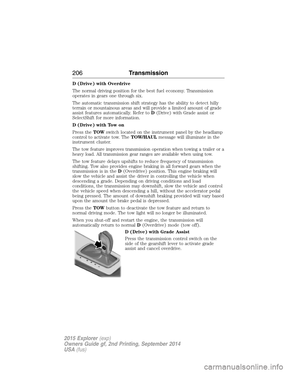
D (Drive) with Grade Assist
Press the transmission control switch on the
side of the gearshift lever to activate grade
assist and cancel overdrive.
PRNDL
206Transmission
2015 Explorer(exp)
Owners Guide gf, 2nd Printing, September 2014
USA(fus)
Page 253 of 596
System Display
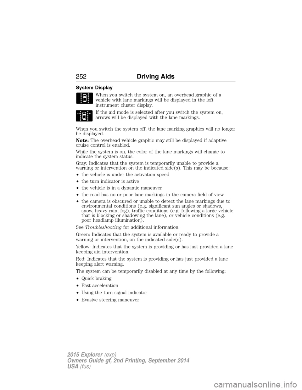
When you switch the system on, an overhead graphic of a
vehicle with lane markings will be displayed in the left
instrument cluster display.
If the aid mode is selected after you switch the system on,
arrows will be displayed with the lane markings.
When you switch the system off, the lane marking graphics will no longer
be displayed.
Note:The overhead vehicle graphic may still be displayed if adaptive
cruise control is enabled.
While the system is on, the color of the lane markings will change to
indicate the system status.
Gray: Indicates that the system is temporarily unable to provide a
warning or intervention on the indicated side(s). This may be because:
•the vehicle is under the activation speed
•the turn indicator is active
•the vehicle is in a dynamic maneuver
•the road has no or poor lane markings in the camera field-of-view
•the camera is obscured or unable to detect the lane markings due to
environmental conditions (e.g. significant sun angles or shadows,
snow, heavy rain, fog), traffic conditions (e.g. following a large vehicle
that is blocking or shadowing the lane), or vehicle conditions (e.g.
poor headlamp illumination).
SeeTroubleshootingfor additional information.
Green: Indicates that the system is available or ready to provide a
warning or intervention, on the indicated side(s).
Yellow: Indicates that the system is providing or has just provided a lane
keeping aid intervention.
Red: Indicates that the system is providing or has just provided a lane
keeping alert warning.
The system can be temporarily disabled at any time by the following:
•Quick braking
•Fast acceleration
•Using the turn signal indicator
•Evasive steering maneuver
252Driving Aids
2015 Explorer(exp)
Owners Guide gf, 2nd Printing, September 2014
USA(fus)
Page 263 of 596
•Pedestrians or objects in the roadway.
•Oncoming vehicles in the same lane.
•Severe weather conditions (see blocked sensor section).
•Debris build-up on the grille near the headlamps (see blocked sensor
section).
•Small distance to vehicle ahead.
•Steering wheel and pedal movements are large (very active driving
style).
•High interior temperatures, which may deactivate the illumination or
the warning lamps until the interior temperature reduces (audible
warning still sounds).
Certain conditions may reduce the visibility of the warning lamp;
therefore, it is recommended to keep the audible warning on.
If the front end of the vehicle is hit or damaged, the radar sensing zone
may be altered causing missed or false collision warnings. See your
authorized dealer to have your collision warning radar checked for
proper coverage and operation.
STEERING
Electric Power Steering
WARNING:The electric power steering system has diagnostic
checks that continuously monitor the system to ensure proper
operation. When a system error is detected a steering message will
appear in the information display.
WARNING:The electric power steering system has diagnostic
checks that continuously monitor the system to ensure proper
operation of the electronic system. When an electronic error is
detected, a message will be displayed in the information display. If this
happens, stop the vehicle in a safe place, and turn off the engine. After
at least 10 seconds, reset the system by restarting the engine, and
watch the information display for a steering message. If a steering
message returns, or returns while driving, take the vehicle to your
dealer to have it checked.
262Driving Aids
2015 Explorer(exp)
Owners Guide gf, 2nd Printing, September 2014
USA(fus)
Page 304 of 596
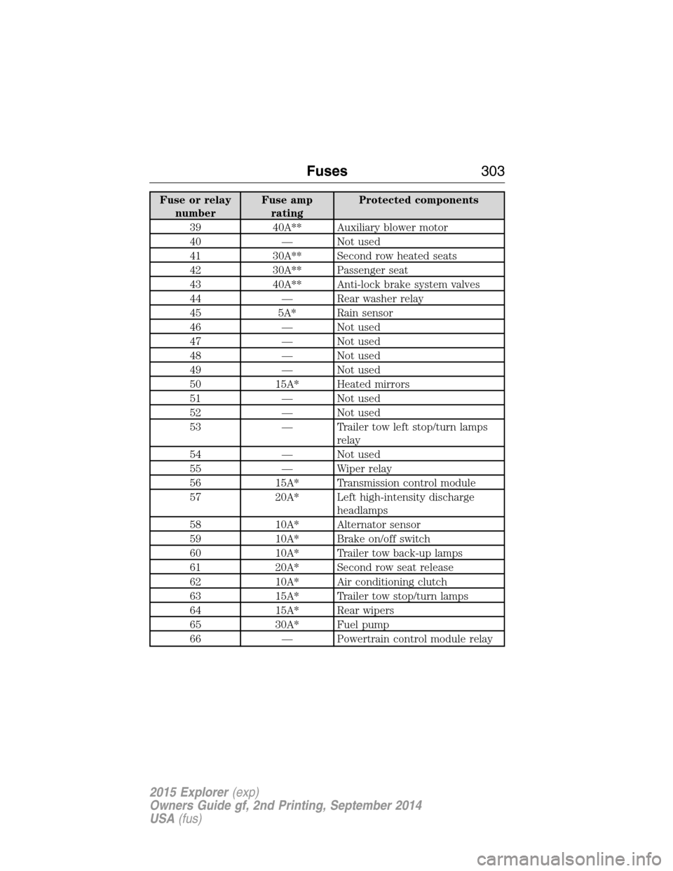
Fuse or relay
numberFuse amp
ratingProtected components
39 40A** Auxiliary blower motor
40 — Not used
41 30A** Second row heated seats
42 30A** Passenger seat
43 40A** Anti-lock brake system valves
44 — Rear washer relay
45 5A* Rain sensor
46 — Not used
47 — Not used
48 — Not used
49 — Not used
50 15A* Heated mirrors
51 — Not used
52 — Not used
53 — Trailer tow left stop/turn lamps
relay
54 — Not used
55 — Wiper relay
56 15A* Transmission control module
57 20A* Left high-intensity discharge
headlamps
58 10A* Alternator sensor
59 10A* Brake on/off switch
60 10A* Trailer tow back-up lamps
61 20A* Second row seat release
62 10A* Air conditioning clutch
63 15A* Trailer tow stop/turn lamps
64 15A* Rear wipers
65 30A* Fuel pump
66 — Powertrain control module relay
Fuses303
2015 Explorer(exp)
Owners Guide gf, 2nd Printing, September 2014
USA(fus)
Page 305 of 596
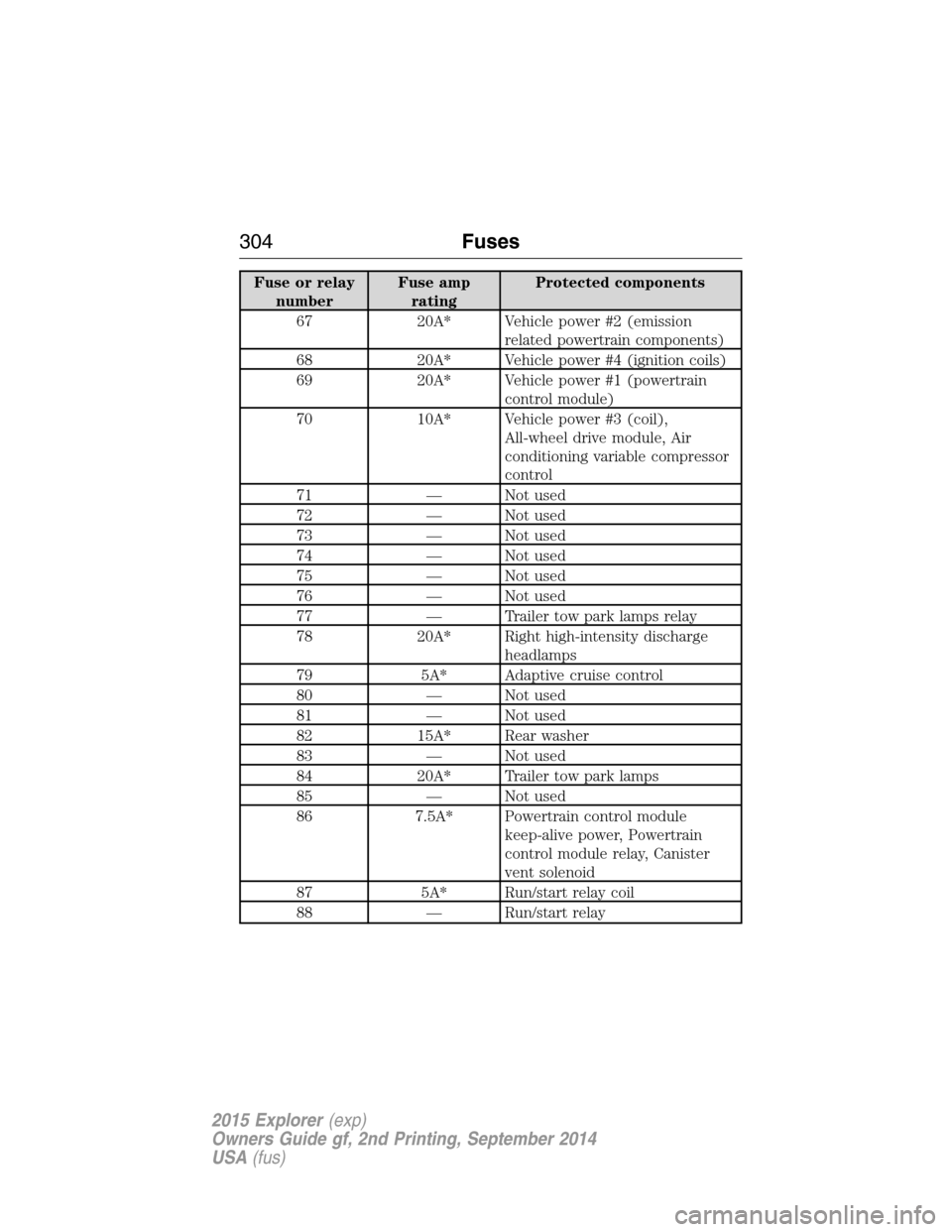
Fuse or relay
numberFuse amp
ratingProtected components
67 20A* Vehicle power #2 (emission
related powertrain components)
68 20A* Vehicle power #4 (ignition coils)
69 20A* Vehicle power #1 (powertrain
control module)
70 10A* Vehicle power #3 (coil),
All-wheel drive module, Air
conditioning variable compressor
control
71 — Not used
72 — Not used
73 — Not used
74 — Not used
75 — Not used
76 — Not used
77 — Trailer tow park lamps relay
78 20A* Right high-intensity discharge
headlamps
79 5A* Adaptive cruise control
80 — Not used
81 — Not used
82 15A* Rear washer
83 — Not used
84 20A* Trailer tow park lamps
85 — Not used
86 7.5A* Powertrain control module
keep-alive power, Powertrain
control module relay, Canister
vent solenoid
87 5A* Run/start relay coil
88 — Run/start relay
304Fuses
2015 Explorer(exp)
Owners Guide gf, 2nd Printing, September 2014
USA(fus)
Page 308 of 596
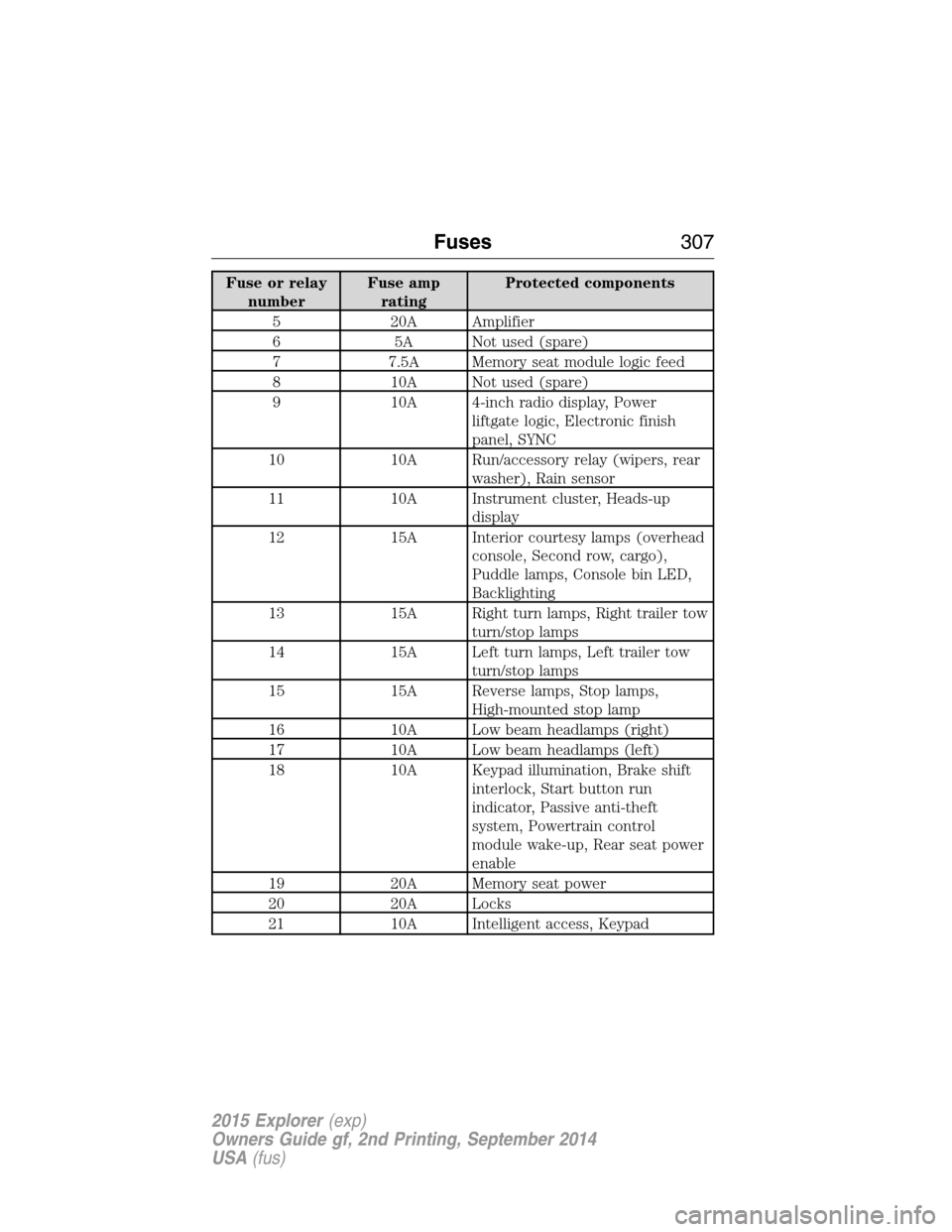
Fuse or relay
numberFuse amp
ratingProtected components
5 20A Amplifier
6 5A Not used (spare)
7 7.5A Memory seat module logic feed
8 10A Not used (spare)
9 10A 4-inch radio display, Power
liftgate logic, Electronic finish
panel, SYNC
10 10A Run/accessory relay (wipers, rear
washer), Rain sensor
11 10A Instrument cluster, Heads-up
display
12 15A Interior courtesy lamps (overhead
console, Second row, cargo),
Puddle lamps, Console bin LED,
Backlighting
13 15A Right turn lamps, Right trailer tow
turn/stop lamps
14 15A Left turn lamps, Left trailer tow
turn/stop lamps
15 15A Reverse lamps, Stop lamps,
High-mounted stop lamp
16 10A Low beam headlamps (right)
17 10A Low beam headlamps (left)
18 10A Keypad illumination, Brake shift
interlock, Start button run
indicator, Passive anti-theft
system, Powertrain control
module wake-up, Rear seat power
enable
19 20A Memory seat power
20 20A Locks
21 10A Intelligent access, Keypad
Fuses307
2015 Explorer(exp)
Owners Guide gf, 2nd Printing, September 2014
USA(fus)
Page 309 of 596
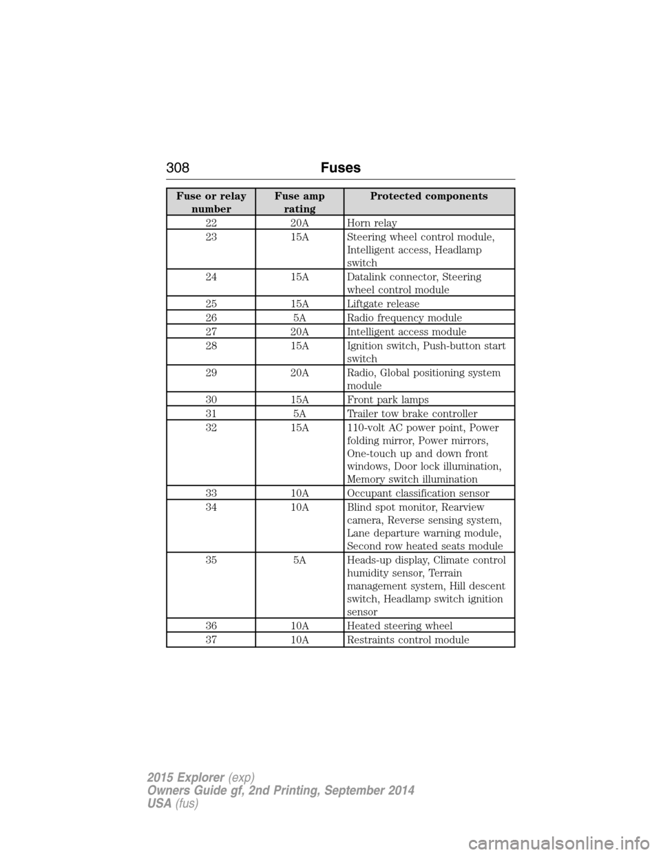
Fuse or relay
numberFuse amp
ratingProtected components
22 20A Horn relay
23 15A Steering wheel control module,
Intelligent access, Headlamp
switch
24 15A Datalink connector, Steering
wheel control module
25 15A Liftgate release
26 5A Radio frequency module
27 20A Intelligent access module
28 15A Ignition switch, Push-button start
switch
29 20A Radio, Global positioning system
module
30 15A Front park lamps
31 5A Trailer tow brake controller
32 15A 110-volt AC power point, Power
folding mirror, Power mirrors,
One-touch up and down front
windows, Door lock illumination,
Memory switch illumination
33 10A Occupant classification sensor
34 10A Blind spot monitor, Rearview
camera, Reverse sensing system,
Lane departure warning module,
Second row heated seats module
35 5A Heads-up display, Climate control
humidity sensor, Terrain
management system, Hill descent
switch, Headlamp switch ignition
sensor
36 10A Heated steering wheel
37 10A Restraints control module
308Fuses
2015 Explorer(exp)
Owners Guide gf, 2nd Printing, September 2014
USA(fus)
Page 310 of 596
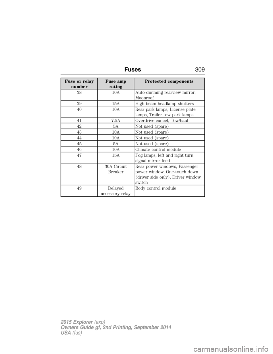
Fuse or relay
numberFuse amp
ratingProtected components
38 10A Auto-dimming rearview mirror,
Moonroof
39 15A High beam headlamp shutters
40 10A Rear park lamps, License plate
lamps, Trailer tow park lamps
41 7.5A Overdrive cancel, Tow/haul
42 5A Not used (spare)
43 10A Not used (spare)
44 10A Not used (spare)
45 5A Not used (spare)
46 10A Climate control module
47 15A Fog lamps, left and right turn
signal mirror feed
48 30A Circuit
BreakerRear power windows, Passenger
power window, One-touch down
(driver side only), Driver window
switch
49 Delayed
accessory relayBody control module
Fuses309
2015 Explorer(exp)
Owners Guide gf, 2nd Printing, September 2014
USA(fus)
Page 334 of 596
7. Lower the driver’s side of the cover and slide the
three tabs on the cover into the three slots in the
housing.
8. Lower the passenger’s side of the cover. Engage
the two clamps to secure the cover to the housing.
ADJUSTING THE HEADLAMPS
The headlamps on your vehicle are properly aimed at the assembly plant.
If your vehicle has been in an accident, an authorized dealer should
check the alignment of your headlamps.
Vertical Aim Adjustment
The headlamps on your vehicle can only be vertically adjusted. Your
vehicle does not require horizontal aim adjustments.
To adjust the headlamps:
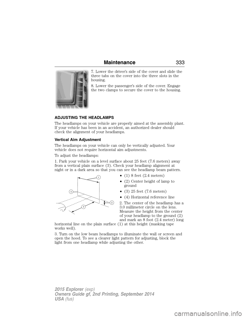
1. Park your vehicle on a level surface about 25 feet (7.6 meters) away
from a vertical plain surface (3). Check your headlamp alignment at
night or in a dark area so that you can see the headlamp beam pattern.
•(1) 8 feet (2.4 meters)
•(2) Center height of lamp to
ground
•(3) 25 feet (7.6 meters)
•(4) Horizontal reference line
2. The center of the headlamp has a
3.0 millimeter circle on the lens.
Measure the height from the center
of your headlamp to the ground (2)
and mark an 8 foot (2.4 meter) long
horizontal line on the plain surface (1) at this height (masking tape
works well).
3. Turn on the low beam headlamps to illuminate the wall or screen and
open the hood. To see a clearer light pattern for adjusting, block the
light from one headlamp while adjusting the other.
Maintenance333
2015 Explorer(exp)
Owners Guide gf, 2nd Printing, September 2014
USA(fus)