warning light FORD EXPLORER 2021 Owner's Manual
[x] Cancel search | Manufacturer: FORD, Model Year: 2021, Model line: EXPLORER, Model: FORD EXPLORER 2021Pages: 577, PDF Size: 9.79 MB
Page 149 of 577
SITTING IN THE CORRECT
POSITION
WARNING: Sitting improperly, out
of position or with the seatback reclined
too far can take weight off the seat
cushion and affect the decision of the
passenger sensing system, resulting in
serious injury or death in the event of a
crash. Always sit upright against your
seat back, with your feet on the floor. WARNING: Do not recline the seat
backrest too far as this can cause the
occupant to slide under the seatbelt,
resulting in personal injury in the event
of a crash. WARNING:
Do not place objects
higher than the top of the seat backrest.
Failure to follow this instruction could
result in personal injury or death in the
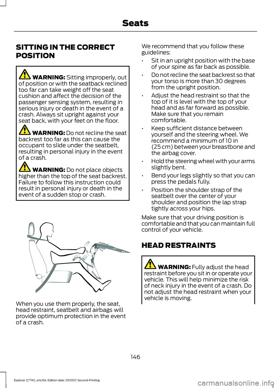
event of a sudden stop or crash. When you use them properly, the seat,
head restraint, seatbelt and airbags will
provide optimum protection in the event
of a crash. We recommend that you follow these
guidelines:
•
Sit in an upright position with the base
of your spine as far back as possible.
• Do not recline the seat backrest so that
your torso is more than 30 degrees
from the upright position.
• Adjust the head restraint so that the
top of it is level with the top of your
head and as far forward as possible.
Make sure that you remain
comfortable.
• Keep sufficient distance between
yourself and the steering wheel. We
recommend a minimum of
10 in
(25 cm) between your breastbone and
the airbag cover.
• Hold the steering wheel with your arms
slightly bent.
• Bend your legs slightly so that you can
press the pedals fully.
• Position the shoulder strap of the
seatbelt over the center of your
shoulder and position the lap strap
tightly across your hips.
Make sure that your driving position is
comfortable and that you can maintain full
control of your vehicle.
HEAD RESTRAINTS WARNING:
Fully adjust the head
restraint before you sit in or operate your
vehicle. This will help minimize the risk
of neck injury in the event of a crash. Do
not adjust the head restraint when your
vehicle is moving.
146
Explorer (CTW), enUSA, Edition date: 202007, Second-Printing SeatsE68595
Page 165 of 577
UNIVERSAL GARAGE DOOR
OPENER
HomeLink Wireless Control
System
WARNING: Do not use the system
with any garage door opener that does
not have the safety stop and reverse
feature as required by U.S. Federal
Safety Standards (this includes any
garage door opener manufactured
before April 1, 1982). A garage door
opener which cannot detect an object,
signaling the door to stop and reverse,
does not meet current federal safety
standards. Using a garage door opener
without these features increases the risk
of serious injury or death.
Note: Make sure that the garage door and
security device are free from obstruction
when you are programming. Do not program
the system with the vehicle in the garage.
Note: Make sure you keep the original
remote control transmitter for use in other
vehicles as well as for future system
programming.
Note: We recommend that upon the sale
or lease termination of your vehicle, you
erase the programmed function buttons for
security reasons. See Erasing the Function
Button Codes
.
Note: You can program a maximum of
three devices. To change or replace any of
the three devices after it has been initially
programmed, you must first erase the
current settings. See Erasing the Function
Button Codes
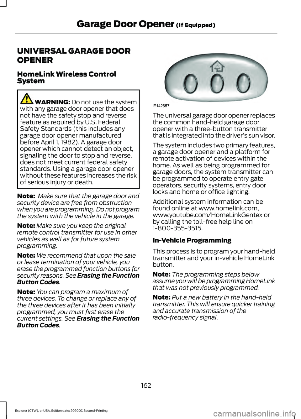
. The universal garage door opener replaces
the common hand-held garage door
opener with a three-button transmitter
that is integrated into the driver
’s sun visor.
The system includes two primary features,
a garage door opener and a platform for
remote activation of devices within the
home. As well as being programmed for
garage doors, the system transmitter can
be programmed to operate entry gate
operators, security systems, entry door
locks and home or office lighting.
Additional system information can be
found online at www.homelink.com,
www.youtube.com/HomeLinkGentex or
by calling the toll-free help line on
1-800-355-3515.
In-Vehicle Programming
This process is to program your hand-held
transmitter and your in-vehicle HomeLink
button.
Note: The programming steps below
assume you will be programming HomeLink
that was not previously programmed.
Note: Put a new battery in the hand-held
transmitter. This will ensure quicker training
and accurate transmission of the
radio-frequency signal.
162
Explorer (CTW), enUSA, Edition date: 202007, Second-Printing Garage Door Opener
(If Equipped)E142657
Page 169 of 577
5. Press and hold the previously
programmed button on the visor for 2
seconds. Repeat this step up to 3 times
until the garage door moves.
Programming is now complete.
Clearing a HomeLink Device
To erase programming from the three
HomeLink buttons press and hold the two
outer HomeLink buttons until the indicator
light begins to flash. The indicator light will
begin flashing in 10 to 20 seconds, at which
time both buttons should be released.
Programming has now been erased, and
the indicator light should blink slowly to
indicate the device is in train mode when
any of the three HomeLink buttons are
pressed.
FCC and RSS-210 Industry Canada
Compliance
This device complies with Part 15 of the
FCC Rules and with RSS-210 of Industry
Canada. Operation is subject to the
following two conditions: (1) this device
may not cause harmful interference, and
(2) this device must accept any
interference received, including
interference that may cause undesired
operation. WARNING: Changes or
modifications not expressively approved
by the party responsible for compliance
could void the user's authority to operate
the equipment. The term "IC:" before the
radio certification number only signifies
that Industry Canada technical
specifications were met. This equipment complies with FCC
radiation exposure limits set forth for an
uncontrolled environment. End Users must
follow the specific operating instructions
for satisfying RF exposure compliance. This
transmitter must be at least
8 in (20 cm)
from the user and must not be co-located
or operating in conjunction with any other
antenna or transmitter.
The term “IC:” before the
certification/registration number only
signifies that Industry Canada technical
specifications were met.
166
Explorer (CTW), enUSA, Edition date: 202007, Second-Printing Garage Door Opener
(If Equipped)
Page 170 of 577
12 Volt DC Power Point
WARNING: Do not plug optional
electrical accessories into the cigar
lighter socket. Incorrect use of the cigar
lighter can cause damage not covered
by the vehicle warranty, and can result
in fire or serious injury.
Note: When you switch the ignition on, you
can use the socket to power 12 volt
appliances with a maximum current rating
of 15 amps.
Note: If the power supply does not work
after you switch the ignition off, switch the
ignition on.
Note: Do not hang any accessory from the
accessory plug.
Note: Do not use the power point over the
vehicle capacity of 12 volt DC 180 watts or
a fuse may blow.
Note: Always keep the power point caps
closed when not in use.
Do not insert objects other than an
accessory plug into the power point. This
damages the power point and may blow
the fuse.
Run the vehicle for full capacity use of the
power point.
To prevent the battery from running out of
charge:
• Do not use the power point longer than
necessary when the vehicle is not
running.
• Do not leave devices plugged in
overnight or when you park your vehicle
for extended periods. USB Port and Power Point
Locations
USB Ports and Power Points may be in the
following locations:
•
On the lower instrument panel.
• Inside the center console.
• On the front of the center console.
• On the rear of the center console.
• In the cargo area.
• On the passenger side floor panel.
• 3rd row on the quarter trim panels.
Note: Some of the USB ports may not have
data transfer capabilities.
Note: Incorrect use of the USB ports can
cause damage not covered by the vehicle
warranty.
110 Volt AC Power Point
(If Equipped) WARNING:
Do not keep electrical
devices plugged in the power point
whenever the device is not in use. Do not
use any extension cord with the 110 volt
AC power point, since it will defeat the
safety protection design. Doing so may
cause the power point to overload due
to powering multiple devices that can
reach beyond the 150 watt load limit and
could result in fire or serious injury.
Note: The power point turns off when you
switch off the ignition, when the vehicle is
not in accessory mode or when the battery
voltage drops below 11 volts.
You can use the power point for electric
devices that require up to 150 watts. It is
on the rear of the center console.
167
Explorer (CTW), enUSA, Edition date: 202007, Second-Printing Auxiliary Power Points
Page 171 of 577
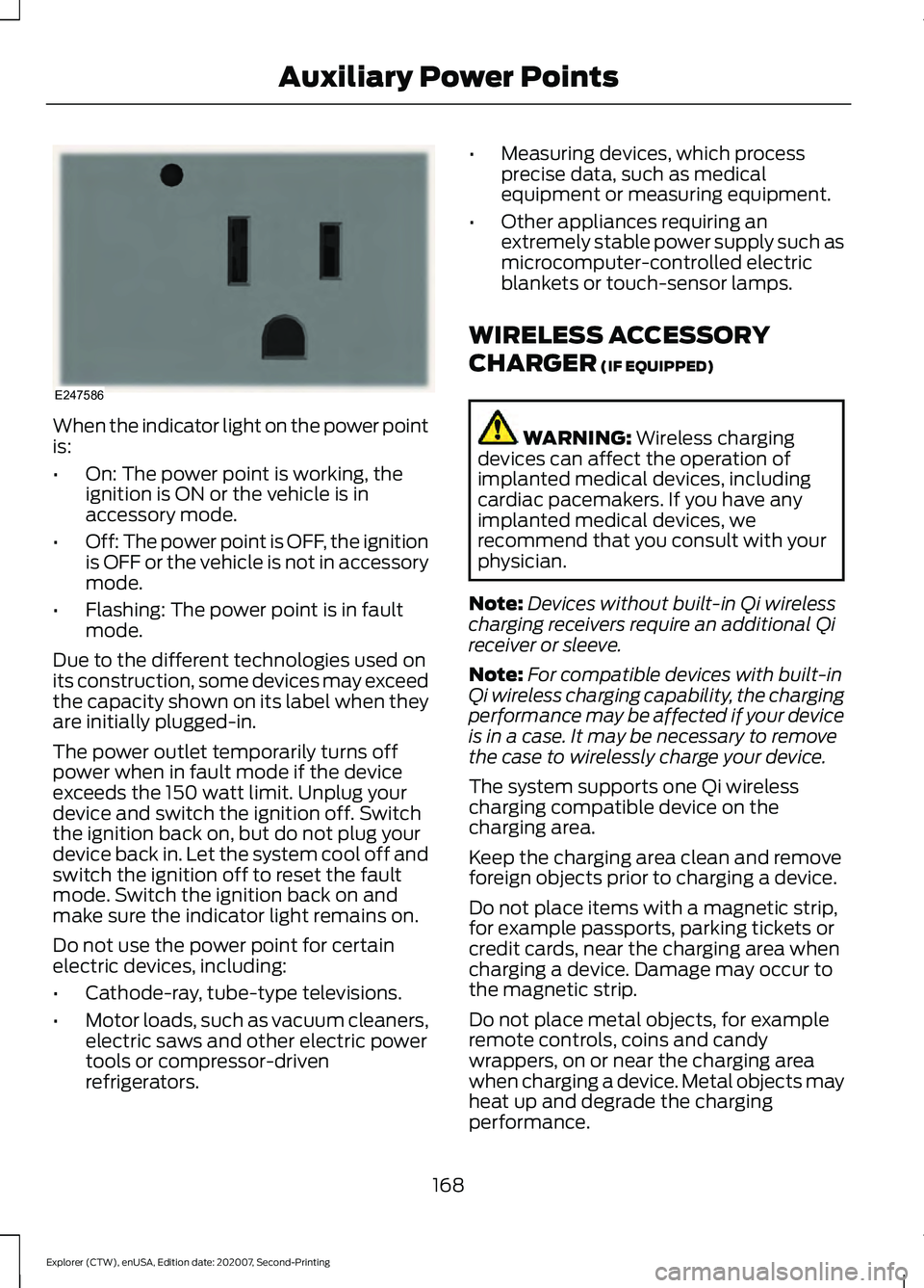
When the indicator light on the power point
is:
•
On: The power point is working, the
ignition is ON or the vehicle is in
accessory mode.
• Off: The power point is OFF, the ignition
is OFF or the vehicle is not in accessory
mode.
• Flashing: The power point is in fault
mode.
Due to the different technologies used on
its construction, some devices may exceed
the capacity shown on its label when they
are initially plugged-in.
The power outlet temporarily turns off
power when in fault mode if the device
exceeds the 150 watt limit. Unplug your
device and switch the ignition off. Switch
the ignition back on, but do not plug your
device back in. Let the system cool off and
switch the ignition off to reset the fault
mode. Switch the ignition back on and
make sure the indicator light remains on.
Do not use the power point for certain
electric devices, including:
• Cathode-ray, tube-type televisions.
• Motor loads, such as vacuum cleaners,
electric saws and other electric power
tools or compressor-driven
refrigerators. •
Measuring devices, which process
precise data, such as medical
equipment or measuring equipment.
• Other appliances requiring an
extremely stable power supply such as
microcomputer-controlled electric
blankets or touch-sensor lamps.
WIRELESS ACCESSORY
CHARGER (IF EQUIPPED) WARNING:
Wireless charging
devices can affect the operation of
implanted medical devices, including
cardiac pacemakers. If you have any
implanted medical devices, we
recommend that you consult with your
physician.
Note: Devices without built-in Qi wireless
charging receivers require an additional Qi
receiver or sleeve.
Note: For compatible devices with built-in
Qi wireless charging capability, the charging
performance may be affected if your device
is in a case. It may be necessary to remove
the case to wirelessly charge your device.
The system supports one Qi wireless
charging compatible device on the
charging area.
Keep the charging area clean and remove
foreign objects prior to charging a device.
Do not place items with a magnetic strip,
for example passports, parking tickets or
credit cards, near the charging area when
charging a device. Damage may occur to
the magnetic strip.
Do not place metal objects, for example
remote controls, coins and candy
wrappers, on or near the charging area
when charging a device. Metal objects may
heat up and degrade the charging
performance.
168
Explorer (CTW), enUSA, Edition date: 202007, Second-Printing Auxiliary Power PointsE247586
Page 176 of 577
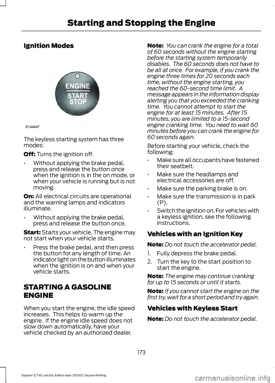
Ignition Modes
The keyless starting system has three
modes:
Off: Turns the ignition off.
• Without applying the brake pedal,
press and release the button once
when the ignition is in the on mode, or
when your vehicle is running but is not
moving.
On:
All electrical circuits are operational
and the warning lamps and indicators
illuminate.
• Without applying the brake pedal,
press and release the button once.
Start:
Starts your vehicle. The engine may
not start when your vehicle starts.
• Press the brake pedal, and then press
the button for any length of time. An
indicator light on the button illuminates
when the ignition is on and when your
vehicle starts.
STARTING A GASOLINE
ENGINE
When you start the engine, the idle speed
increases. This helps to warm up the
engine. If the engine idle speed does not
slow down automatically, have your
vehicle checked by an authorized dealer. Note:
You can crank the engine for a total
of 60 seconds without the engine starting
before the starting system temporarily
disables. The 60 seconds does not have to
be all at once. For example, if you crank the
engine three times for 20 seconds each
time, without the engine starting, you
reached the 60-second time limit. A
message appears in the information display
alerting you that you exceeded the cranking
time. You cannot attempt to start the
engine for at least 15 minutes. After 15
minutes, you are limited to a 15-second
engine cranking time. You need to wait 60
minutes before you can crank the engine for
60 seconds again.
Before starting your vehicle, check the
following:
• Make sure all occupants have fastened
their seatbelt.
• Make sure the headlamps and
electrical accessories are off.
• Make sure the parking brake is on.
• Make sure the transmission is in park
(P).
• Switch the ignition on. For vehicles with
a keyless ignition, see the following
instructions.
Vehicles with an Ignition Key
Note: Do not touch the accelerator pedal.
1. Fully depress the brake pedal.
2. Turn the key to the start position to start the engine.
Note: The engine may continue cranking
for up to 15 seconds or until it starts.
Note: If you cannot start the engine on the
first try, wait for a short period and try again.
Vehicles with Keyless Start
Note: Do not touch the accelerator pedal.
173
Explorer (CTW), enUSA, Edition date: 202007, Second-Printing Starting and Stopping the EngineE144447
Page 194 of 577
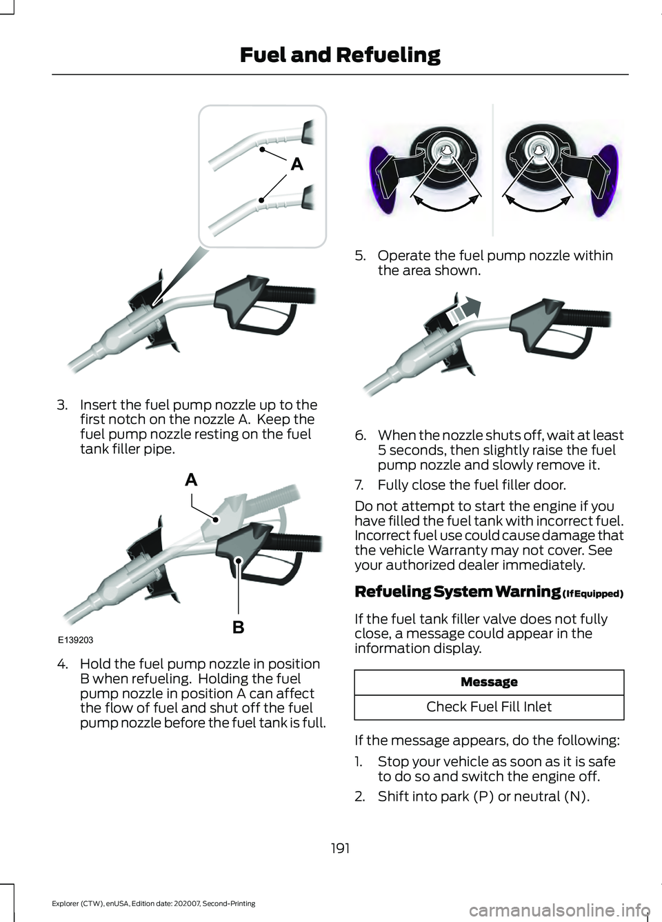
3. Insert the fuel pump nozzle up to the
first notch on the nozzle A. Keep the
fuel pump nozzle resting on the fuel
tank filler pipe. 4. Hold the fuel pump nozzle in position
B when refueling. Holding the fuel
pump nozzle in position A can affect
the flow of fuel and shut off the fuel
pump nozzle before the fuel tank is full. 5. Operate the fuel pump nozzle within
the area shown. 6.
When the nozzle shuts off, wait at least
5 seconds, then slightly raise the fuel
pump nozzle and slowly remove it.
7. Fully close the fuel filler door.
Do not attempt to start the engine if you
have filled the fuel tank with incorrect fuel.
Incorrect fuel use could cause damage that
the vehicle Warranty may not cover. See
your authorized dealer immediately.
Refueling System Warning (If Equipped)
If the fuel tank filler valve does not fully
close, a message could appear in the
information display. Message
Check Fuel Fill Inlet
If the message appears, do the following:
1. Stop your vehicle as soon as it is safe to do so and switch the engine off.
2. Shift into park (P) or neutral (N).
191
Explorer (CTW), enUSA, Edition date: 202007, Second-Printing Fuel and RefuelingE139202 E139203
A
B E337395 E119081
Page 199 of 577
EMISSION LAW
WARNING: Do not remove or alter
the original equipment floor covering or
insulation between it and the metal floor
of the vehicle. The floor covering and
insulation protect occupants of the
vehicle from the engine and exhaust
system heat and noise. On vehicles with
no original equipment floor covering
insulation, do not carry passengers in a
manner that permits prolonged skin
contact with the metal floor. Failure to
follow these instructions may result in
fire or personal injury.
U.S. federal laws and certain state laws
prohibit removing or rendering inoperative
emission control system components.
Similar federal or provincial laws may
apply in Canada. We do not approve of any
vehicle modification without first
determining applicable laws. Tampering with emissions
control systems including
related sensors or the Diesel
Exhaust Fluid system can result in reduced
engine power and the illumination of the
service engine soon light. Tampering With a Noise Control
System
Federal laws prohibit the following acts:
•
Removal or rendering inoperative by
any person other than for purposes of
maintenance.
• Repair or replacement of any device or
element of the design incorporated into
a new vehicle for the purpose of noise
control prior to its sale or delivery to
the ultimate purchaser or while it is in
use.
• The use of the vehicle after any person
removes or renders inoperative any
device or element of the design.
The U.S. Environmental Protection Agency
may presume to constitute tampering as
follows:
• Removal of hood blanket, fender apron
absorbers, fender apron barriers,
underbody noise shields or acoustically
absorptive material.
• Tampering or rendering inoperative the
engine speed governor, to allow engine
speed to exceed manufacturer
specifications.
If the engine does not start, runs rough,
experiences a decrease in engine
performance, experiences excess fuel
consumption or produces excessive
exhaust smoke, check for the following:
• A plugged or disconnected air inlet
system hose.
• A plugged engine air filter element.
• Water in the fuel filter and water
separator.
• A clogged fuel filter.
• Contaminated fuel.
• Air in the fuel system, due to loose
connections.
• An open or pinched sensor hose.
• Incorrect engine oil level.
196
Explorer (CTW), enUSA, Edition date: 202007, Second-Printing Engine Emission Control
Page 201 of 577
Illumination of the service engine soon
indicator, charging system warning light or
the temperature warning light, fluid leaks,
strange odors, smoke or loss of engine
power could indicate that the emission
control system is not working properly.
An improperly operating or damaged
exhaust system may allow exhaust to
enter the vehicle. Have a damaged or
improperly operating exhaust system
inspected and repaired immediately.
Do not make any unauthorized changes to
your vehicle or engine. By law, vehicle
owners and anyone who manufactures,
repairs, services, sells, leases, trades
vehicles, or supervises a fleet of vehicles
are not permitted to intentionally remove
an emission control device or prevent it
from working. Information about your
vehicle
’s emission system is on the Vehicle
Emission Control Information Decal
located on or near the engine. This decal
also lists engine displacement.
Please consult your warranty information
for complete details.
On-Board Diagnostics (OBD-II)
Your vehicle has a computer known as the
on-board diagnostics system (OBD-II) that
monitors the engine ’s emission control
system. The system protects the
environment by making sure that your
vehicle continues to meet government
emission standards. The OBD-II system
also assists a service technician in properly
servicing your vehicle. When the service engine soon
indicator illuminates, the OBD-II
system has detected a
malfunction. Temporary malfunctions may
cause the service engine soon indicator to
illuminate. Examples are: 1. Your vehicle has run out of fuel
—the
engine may misfire or run poorly.
2. Poor fuel quality or water in the fuel —the engine may misfire or run
poorly.
3. The fuel fill inlet may not have closed properly. See Refueling (page 189).
4. Driving through deep water —the
electrical system may be wet.
You can correct these temporary
malfunctions by filling the fuel tank with
good quality fuel, properly closing the fuel
fill inlet or letting the electrical system dry
out. After three driving cycles without these
or any other temporary malfunctions
present, the service engine soon indicator
should stay off the next time you start the
engine. A driving cycle consists of a cold
engine startup followed by mixed city and
highway driving. No additional vehicle
service is required.
If the service engine soon indicator remains
on, have your vehicle serviced at the first
available opportunity. Although some
malfunctions detected by the OBD-II may
not have symptoms that are apparent,
continued driving with the service engine
soon indicator on can result in increased
emissions, lower fuel economy, reduced
engine and transmission smoothness and
lead to more costly repairs.
Readiness for Inspection and
Maintenance (I/M) Testing
Some state and provincial and local
governments may have
Inspection/Maintenance (I/M) programs
to inspect the emission control equipment
on your vehicle. Failure to pass this
inspection could prevent you from getting
a vehicle registration. If the service engine soon
indicator is on or the bulb does
not work, your vehicle may need
service. See On-Board Diagnostics.
198
Explorer (CTW), enUSA, Edition date: 202007, Second-Printing Engine Emission Control
Page 217 of 577
GENERAL INFORMATION
Note:
Occasional brake noise is normal. If
a metal-to-metal, continuous grinding or
continuous squeal sound is present, the
brake linings may be worn-out and an
authorized dealer should check them. If the
vehicle has continuous vibration or shudder
in the steering wheel while braking, an
authorized dealer should check your vehicle.
Note: Brake dust may accumulate on the
wheels, even under normal driving
conditions. Some dust is inevitable as the
brakes wear and does not contribute to
brake noise. See Cleaning the Wheels
(page 348).
Wet brakes result in reduced braking
efficiency. Gently press the brake pedal a
few times when driving from a car wash or
standing water to dry the brakes.
Brake Over Accelerator
In the event the accelerator pedal
becomes stuck or entrapped, apply steady
and firm pressure to the brake pedal to
slow the vehicle and reduce engine power.
If you experience this condition, apply the
brakes and bring your vehicle to a safe
stop. Switch the engine off, move the
transmission to park (P) and apply the
parking brake. Inspect the accelerator
pedal and the area around it for any items
or debris that may be obstructing its
movement. If none are found and the
condition persists, have your vehicle towed
to the nearest authorized dealer.
Emergency Brake Assist
Emergency brake assist detects when you
brake heavily by measuring the rate at
which you press the brake pedal. It
provides maximum braking efficiency as
long as you press the pedal. Emergency
brake assist can reduce stopping distances
in critical situations. Anti-lock Brake System
This system helps you maintain steering
control during emergency stops by keeping
the brakes from locking. This lamp momentarily
illuminates when you switch the
ignition on or apply the parking
brake. If the light does not illuminate
during start up, remains on or flashes,
except when you switch the ignition on or
apply the parking brake, the anti-lock
braking system may be disabled. Have the
system checked by an authorized dealer.
If the anti-lock brake system is disabled,
normal braking is still effective. See
Warning Lamps and Indicators (page
107).
Note: Indicators vary depending on region. This lamp also illuminates
momentarily when you switch
the ignition on or apply the
parking brake to confirm the
lamp is working. If it does not
illuminate when you switch the
ignition on, apply the parking brake, or if it
begins to flash at any time, have the
system checked by an authorized dealer.
If the brake warning lamp illuminates with
the parking brake released, have the
system checked immediately.
Regenerative Braking System
This feature is used to simulate the engine
braking of an internal combustion engine
and assist the standard brake system while
recovering some of the energy of motion
and storing it in the battery to improve fuel
economy. The standard brake system is
designed to fully stop the car if
regenerative braking is not available.
During regenerative braking, the motor is
214
Explorer (CTW), enUSA, Edition date: 202007, Second-Printing Brakes E270480