clock FORD EXPLORER 2021 Owners Manual
[x] Cancel search | Manufacturer: FORD, Model Year: 2021, Model line: EXPLORER, Model: FORD EXPLORER 2021Pages: 577, PDF Size: 9.79 MB
Page 40 of 577
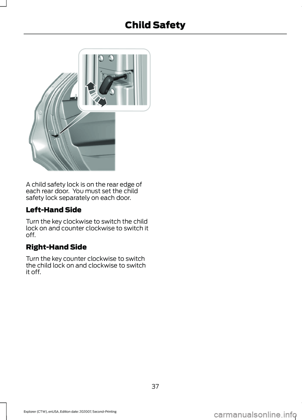
A child safety lock is on the rear edge of
each rear door. You must set the child
safety lock separately on each door.
Left-Hand Side
Turn the key clockwise to switch the child
lock on and counter clockwise to switch it
off.
Right-Hand Side
Turn the key counter clockwise to switch
the child lock on and clockwise to switch
it off.
37
Explorer (CTW), enUSA, Edition date: 202007, Second-Printing Child Safety E287259
Page 330 of 577
8.
Make sure that the oil level is between
the maximum and minimum marks. If
the oil level is at the minimum mark,
add oil immediately. See Capacities
and Specifications (page 391).
9. If the oil level is correct, replace the dipstick and make sure it is fully seated.
Note: Do not remove the dipstick when the
engine is running.
Note: If the oil level is between the
maximum and minimum marks, the oil level
is acceptable. Do not add oil.
Note: The oil consumption of new engines
reaches its normal level after approximately
3,000 mi (5,000 km)
.
Adding Engine Oil WARNING: Do not remove the filler
cap when the engine is running.
Do not use supplemental engine oil
additives because they are unnecessary
and could lead to engine damage that may
not be covered by the vehicle Warranty. Only use oils certified for gasoline engines
by the American Petroleum Institute (API).
An oil with this trademark symbol
conforms to the current engine and
emission system protection standards and
fuel economy requirements of the
International Lubricants Specification
Advisory Committee (ILSAC).
To top up the engine oil level do the
following:
1. Clean the area surrounding the engine
oil filler cap before you remove it.
2. Remove the engine oil filler cap. See Under Hood Overview
(page 323).
Turn it counterclockwise and remove
it.
3. Add engine oil that meets our specifications. See
Capacities and
Specifications (page 391). You may
have to use a funnel to pour the engine
oil into the opening.
4. Recheck the oil level.
5. If the oil level is correct, replace the dipstick and make sure it is fully seated.
6. Replace the engine oil filler cap. Turn it clockwise until you feel a strong
resistance.
Note: Do not add oil further than the
maximum mark. Oil levels above the
maximum mark may cause engine damage.
Note: Make sure you install the oil filler cap
correctly.
Note: Soak up any spillage with an
absorbent cloth immediately.
OIL CHANGE INDICATOR
RESET
Use the information display controls on
the steering wheel to reset the oil change
indicator.
327
Explorer (CTW), enUSA, Edition date: 202007, Second-Printing MaintenanceE142732
Page 335 of 577
It is very important to use prediluted
coolant approved to the correct
specification in order to avoid plugging the
small passageways in the engine cooling
system. See Capacities and
Specifications (page 391). Do not mix
different colors or types of coolant in your
vehicle. Mixing of engine coolants or using
an incorrect coolant may harm the engine
or cooling system components and may
not be covered by the vehicle Warranty.
Note: If prediluted coolant is not available,
use the approved concentrated coolant
diluting it to 50/50 with distilled water. See
Capacities and Specifications (page 391).
Using water that has not been deionised
may contribute to deposit formation,
corrosion and plugging of the small cooling
system passageways.
Note: Coolants marketed for all makes and
models may not be approved to our
specifications and may cause damage to
the cooling system. Resulting component
damage may not be covered by the vehicle
Warranty.
If the coolant level is at or below the
minimum mark, add prediluted coolant
immediately.
To top up the coolant level do the
following:
1. Unscrew the cap slowly. Any pressure escapes as you unscrew the cap.
2. Add prediluted coolant approved to the correct specification. See
Capacities and Specifications (page
391
).
3. Add enough prediluted coolant to reach the correct level.
4. Replace the coolant reservoir cap. Turn
the cap clockwise until it contacts the
hard stop. 5. Check the coolant level in the coolant
reservoir the next few times you drive
your vehicle. If necessary, add enough
prediluted engine coolant to bring the
coolant level to the correct level.
If you have to add more than
1.1 qt (1 L) of
engine coolant per month, have your
vehicle checked as soon as possible.
Operating an engine with a low level of
coolant can result in engine overheating
and possible engine damage.
In case of emergency, you can add a large
amount of water without engine coolant
in order to reach a vehicle service location.
In this instance, qualified personnel:
1. Must drain the cooling system.
2. Chemically clean the coolant system.
3. Refill with engine coolant as soon as possible.
Water alone, without engine coolant, can
cause engine damage from corrosion,
overheating or freezing.
Do not use the following as a coolant
substitute:
• Alcohol.
• Methanol.
• Brine.
• Any coolant mixed with alcohol or
methanol antifreeze.
Alcohol and other liquids can cause engine
damage from overheating or freezing.
Do not add extra inhibitors or additives to
the coolant. These can be harmful and
compromise the corrosion protection of
the coolant.
Recycled Coolant
We do not recommend the use of recycled
coolant as an approved recycling process
is not yet available.
Note: Dispose of used coolant in the
appropriate manner.
332
Explorer (CTW), enUSA, Edition date: 202007, Second-Printing Maintenance
Page 341 of 577
After battery replacement, or in some
cases after charging the battery with an
external charger, the battery management
system requires eight hours of vehicle sleep
time to relearn the battery state of charge.
During this time your vehicle must remain
fully locked with the ignition switched off.
Note:
Prior to relearning the battery state
of charge, the battery management system
may temporarily disable some electrical
systems.
Electrical Accessory Installation
To make sure the battery management
system works correctly, do not connect an
electrical device ground connection
directly to the battery negative post. This
can cause inaccurate measurements of
the battery condition and potential
incorrect system operation.
Note: If you add electrical accessories or
components to the vehicle, it may adversely
affect battery performance and durability.
This may also affect the performance of
other electrical systems in the vehicle.
Remove and Reinstall the Battery
To disconnect or remove the battery, do
the following:
1. Apply the parking brake and switch the
ignition off.
2. Switch all electrical equipment off, for
example lights and radio.
3. Wait a minimum of two minutes before
disconnecting the battery.
Note: The engine management system has
a power hold function and remains powered
for a period of time after you switch the
ignition off. This is to allow diagnostic and
adaptive tables to be stored. Disconnecting
the battery without waiting can cause
damage not covered by the vehicle
Warranty. 4. Disconnect the negative battery cable
terminal.
5. Disconnect the positive battery cable terminal.
6. Remove the battery securing clamp.
7. Remove the battery.
8. To install, reverse the removal procedure.
Note: Before reconnecting the battery,
make sure the ignition remains switched off.
Note: Make sure the battery cable terminals
are fully tightened.
If you disconnect or replace the vehicle
battery, you must reset the following
features:
• Window bounce-back. See Power
Windows (page 96).
• Clock Settings.
• Pre-set radio stations.
Battery Disposal Make sure that you dispose of
old batteries in an
environmentally friendly way.
Seek advice from your local authority
about recycling old batteries.
ADJUSTING THE HEADLAMPS
Vertical Aim Adjustment
If your vehicle has been involved in a crash,
have the aim of the headlamp beam
checked by an authorized dealer.
338
Explorer (CTW), enUSA, Edition date: 202007, Second-Printing MaintenanceE107998
Page 343 of 577
5. Use a suitable tool, for example a
screwdriver or socket wrench, to turn
the adjuster clockwise or
counterclockwise to adjust the vertical
aim of the headlamp. The horizontal
edge of the brighter light should touch
the horizontal reference line.
6. Close the hood and switch off the lamps.
WASHER FLUID CHECK WARNING: If you operate your
vehicle in temperatures below 41.0°F
(5°C), use washer fluid with antifreeze
protection. Failure to use washer fluid
with antifreeze protection in cold
weather could result in impaired
windshield vision and increase the risk
of injury or accident.
Note: The front and rear washer systems
are supplied from the same reservoir.
Add fluid to fill the reservoir if the level is
low. Only use a washer fluid that meets
our specifications. See
Capacities and
Specifications (page 391).
State or local regulations on volatile
organic compounds may restrict the use
of methanol, a common windshield washer
antifreeze additive. Washer fluids
containing non-methanol antifreeze
agents should be used only if they provide
cold weather protection without damaging
the vehicle ’s paint finish, wiper blades or
washer system.
FUEL FILTER
Your vehicle is equipped with a lifetime
fuel filter that is integrated with the fuel
tank. Regular maintenance or replacement
is not needed. CHECKING THE WIPER
BLADES
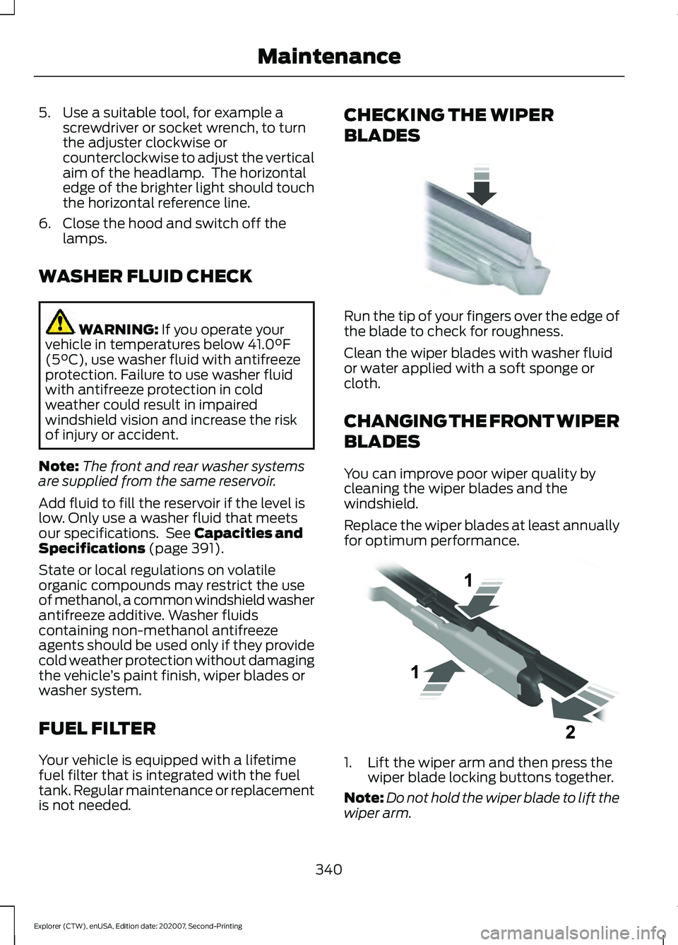
Run the tip of your fingers over the edge of
the blade to check for roughness.
Clean the wiper blades with washer fluid
or water applied with a soft sponge or
cloth.
CHANGING THE FRONT WIPER
BLADES
You can improve poor wiper quality by
cleaning the wiper blades and the
windshield.
Replace the wiper blades at least annually
for optimum performance.
1. Lift the wiper arm and then press the
wiper blade locking buttons together.
Note: Do not hold the wiper blade to lift the
wiper arm.
340
Explorer (CTW), enUSA, Edition date: 202007, Second-Printing MaintenanceE142463 E129990
Page 345 of 577
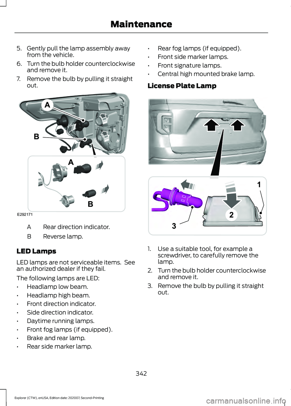
5. Gently pull the lamp assembly away
from the vehicle.
6. Turn the bulb holder counterclockwise
and remove it.
7. Remove the bulb by pulling it straight out. Rear direction indicator.
A
Reverse lamp.
B
LED Lamps
LED lamps are not serviceable items. See
an authorized dealer if they fail.
The following lamps are LED:
• Headlamp low beam.
• Headlamp high beam.
• Front direction indicator.
• Side direction indicator.
• Daytime running lamps.
• Front fog lamps (if equipped).
• Brake and rear lamp.
• Rear side marker lamp. •
Rear fog lamps (if equipped).
• Front side marker lamps.
• Front signature lamps.
• Central high mounted brake lamp.
License Plate Lamp 1. Use a suitable tool, for example a
screwdriver, to carefully remove the
lamp.
2. Turn the bulb holder counterclockwise
and remove it.
3. Remove the bulb by pulling it straight out.
342
Explorer (CTW), enUSA, Edition date: 202007, Second-Printing MaintenanceE292171 A
B
A
12
203A
AE292276
Page 376 of 577
•
To reduce the chances of interference
from another vehicle, perform the
system reset procedure at least 3 ft
(1 m) away from another Ford Motor
Company vehicle undergoing the
system reset procedure at the same
time.
• Do not wait more than two minutes
between resetting each tire sensor or
the system can time-out and you have
to repeat the entire procedure on all
four wheels.
• A double horn sounds indicating the
need to repeat the procedure.
Performing the System Reset Procedure
Read the entire procedure before
attempting.
1. Drive the vehicle above
20 mph
(32 km/h) for at least two minutes,
then park in a safe location where you
can easily get to all four tires and have
access to an air pump.
2. Place the ignition in the off position and
keep the key in the ignition.
3. Cycle the ignition to the on position with the engine off.
4. Turn the hazard flashers on then off three times. You must accomplish this
within 10 seconds. If you successfully
enter the reset mode, the horn sounds
once, the system indicator flashes and
a message shows in the information
display. If this does not occur, please
try again starting at step 2. If after
repeated attempts to enter the reset
mode, the horn does not sound, the
system indicator does not flash and no
message shows in the information
display, seek service from your
authorized dealer. 5. Train the tire pressure monitoring
system sensors in the tires using the
following system reset sequence
starting with the left front tire in the
following clockwise order: Left front -
driver side front tire, Right front -
passenger side front tire, Right rear -
passenger side rear tire, Left rear -
driver side rear tire.
6. Remove the valve cap from the valve stem on the left front tire. Decrease the
air pressure until the horn sounds.
Note: The single horn tone confirms that
the sensor identification code has been
learned by the module for this position. If a
double horn is heard, the reset procedure
was unsuccessful, and you must repeat it.
7. Remove the valve cap from the valve stem on the right front tire. Decrease
the air pressure until the horn sounds.
8. Remove the valve cap from the valve stem on the right rear tire. Decrease the
air pressure until the horn sounds.
9. Remove the valve cap from the valve stem on the left rear tire. Decrease the
air pressure until the horn sounds.
Training is complete after the horn
sounds for the last tire trained, driver
side rear tire, the system indicator
stops flashing, and a message shows
in the information display.
10. Turn the ignition off. If two short horn
beeps are heard, the reset procedure
was unsuccessful and you must
repeat it. If after repeating the
procedure and two short beeps are
heard when the ignition is turned to
off, seek assistance from your
authorized dealer.
373
Explorer (CTW), enUSA, Edition date: 202007, Second-Printing Wheels and Tires
Page 380 of 577
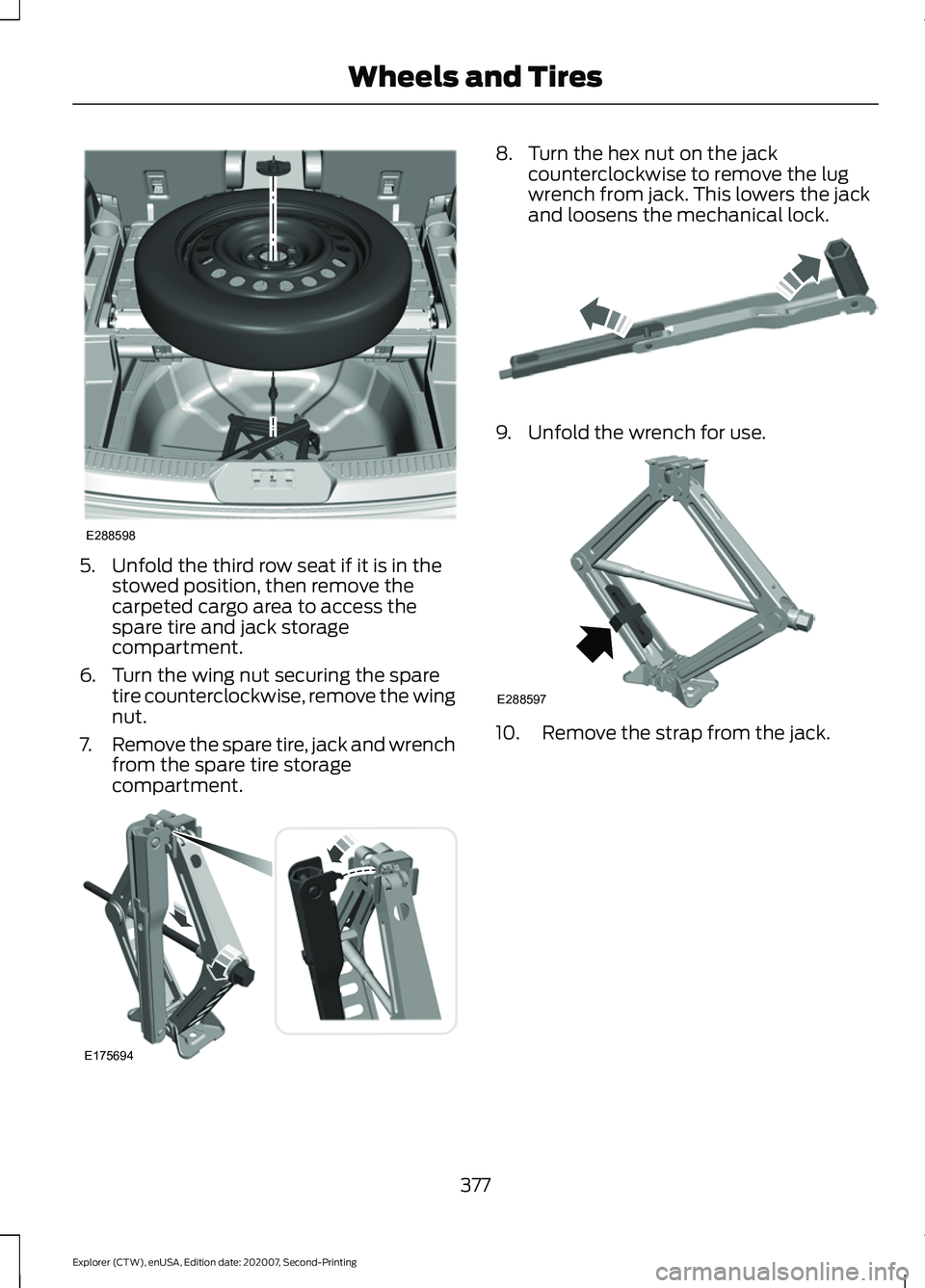
5. Unfold the third row seat if it is in the
stowed position, then remove the
carpeted cargo area to access the
spare tire and jack storage
compartment.
6. Turn the wing nut securing the spare tire counterclockwise, remove the wing
nut.
7. Remove the spare tire, jack and wrench
from the spare tire storage
compartment. 8. Turn the hex nut on the jack
counterclockwise to remove the lug
wrench from jack. This lowers the jack
and loosens the mechanical lock. 9. Unfold the wrench for use.
10. Remove the strap from the jack.
377
Explorer (CTW), enUSA, Edition date: 202007, Second-Printing Wheels and TiresE288598 E175694 E181744 E288597
Page 381 of 577
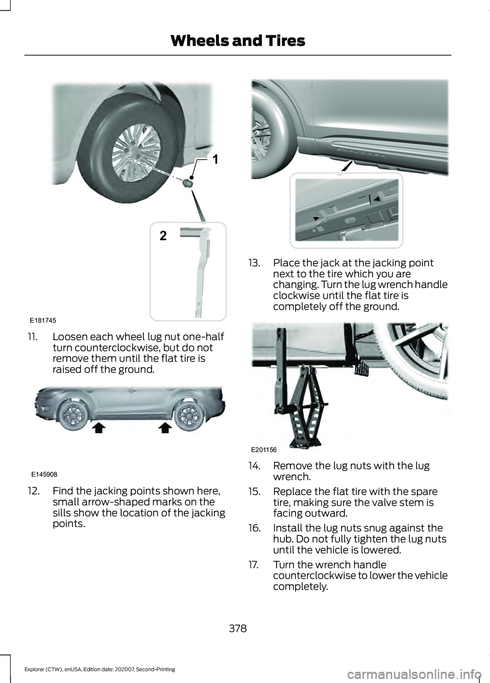
11. Loosen each wheel lug nut one-half
turn counterclockwise, but do not
remove them until the flat tire is
raised off the ground.12. Find the jacking points shown here,
small arrow-shaped marks on the
sills show the location of the jacking
points. 13. Place the jack at the jacking point
next to the tire which you are
changing. Turn the lug wrench handle
clockwise until the flat tire is
completely off the ground. 14. Remove the lug nuts with the lug
wrench.
15. Replace the flat tire with the spare tire, making sure the valve stem is
facing outward.
16. Install the lug nuts snug against the hub. Do not fully tighten the lug nuts
until the vehicle is lowered.
17. Turn the wrench handle counterclockwise to lower the vehicle
completely.
378
Explorer (CTW), enUSA, Edition date: 202007, Second-Printing Wheels and Tires1
E181745
2 E145908 E307859 E201156
Page 382 of 577
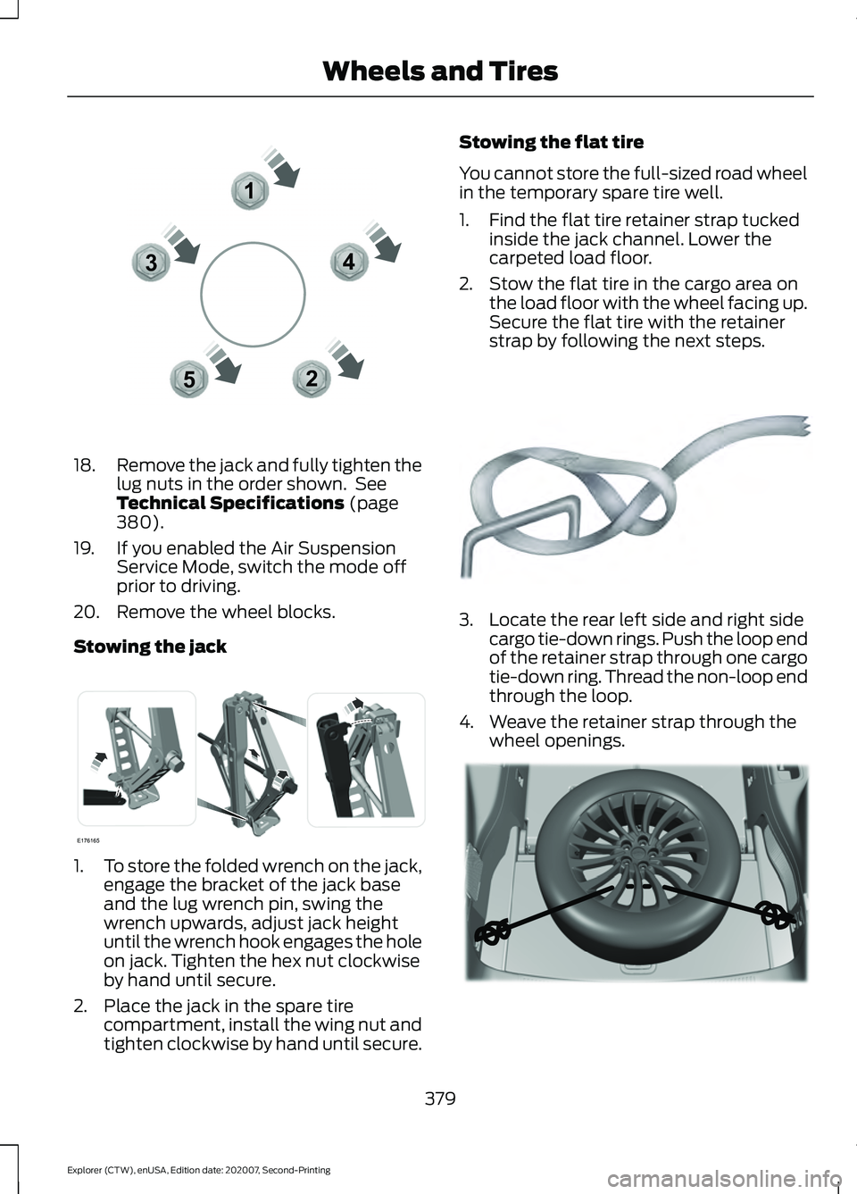
18.
Remove the jack and fully tighten the
lug nuts in the order shown. See
Technical Specifications (page
380).
19. If you enabled the Air Suspension Service Mode, switch the mode off
prior to driving.
20. Remove the wheel blocks.
Stowing the jack 1.
To store the folded wrench on the jack,
engage the bracket of the jack base
and the lug wrench pin, swing the
wrench upwards, adjust jack height
until the wrench hook engages the hole
on jack. Tighten the hex nut clockwise
by hand until secure.
2. Place the jack in the spare tire compartment, install the wing nut and
tighten clockwise by hand until secure. Stowing the flat tire
You cannot store the full-sized road wheel
in the temporary spare tire well.
1. Find the flat tire retainer strap tucked
inside the jack channel. Lower the
carpeted load floor.
2. Stow the flat tire in the cargo area on the load floor with the wheel facing up.
Secure the flat tire with the retainer
strap by following the next steps. 3. Locate the rear left side and right side
cargo tie-down rings. Push the loop end
of the retainer strap through one cargo
tie-down ring. Thread the non-loop end
through the loop.
4. Weave the retainer strap through the wheel openings. 379
Explorer (CTW), enUSA, Edition date: 202007, Second-Printing Wheels and Tires12
3
4
5E306781 E176165 E142906 E294325