maintenance FORD EXPLORER SPORT 2001 1.G Owners Manual
[x] Cancel search | Manufacturer: FORD, Model Year: 2001, Model line: EXPLORER SPORT, Model: FORD EXPLORER SPORT 2001 1.GPages: 256, PDF Size: 2.12 MB
Page 1 of 256
Before driving
Introduction 2
Instrumentation 8
Controls and features 20
Seating and safety restraints 87
Starting and driving
Starting 120
Driving 125
Roadside emergencies 151
Servicing
Maintenance and care 174
Capacities and specifications 224
Customer assistance 232
Reporting safety defects 244
Index 245
All rights reserved. Reproduction by any means, electronic or mechanical including
photocopying, recording or by any information storage and retrieval system or translation
in whole or part is not permitted without written authorization from Ford Motor Company.
Ford may change the contents without notice and without incurring obligation.
Copyright 2001 Ford Motor Company
Contents
1
Page 11 of 256
3.The fuel cap may not have been properly installed and securely
tightened.
These temporary malfunctions can be corrected by filling the fuel tank
with high quality fuel of the recommended octane and/or properly
installing and securely tightening the gas cap. After three driving cycles
without these or any other temporary malfunctions present, theCheck
Enginelight should turn off. (A driving cycle consists of a cold engine
startup followed by mixed city/highway driving.) No additional vehicle
service is required.
If theCheck Enginelight remains on, have your vehicle serviced at the
first available opportunity.
Light is blinking:
Engine misfire is occurring which could damage your catalytic converter.
You should drive in a moderate fashion (avoid heavy acceleration and
deceleration) and have your vehicle serviced at the first available
opportunity.
Under engine misfire conditions, excessive exhaust temperatures
could damage the catalytic converter, the fuel system, interior
floor coverings or other vehicle components, possibly causing a fire.
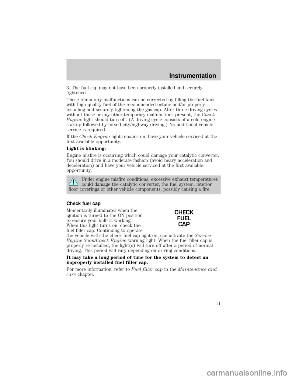
Check fuel cap
Momentarily illuminates when the
ignition is turned to the ON position
to ensure your bulb is working.
When this light turns on, check the
fuel filler cap. Continuing to operate
the vehicle with the check fuel cap light on, can activate theService
Engine Soon/Check Enginewarning light. When the fuel filler cap is
properly re-installed, the light(s) will turn off after a period of normal
driving. This period will vary depending on driving conditions.
It may take a long period of time for the system to detect an
improperly installed fuel filler cap.
For more information, refer toFuel filler capin theMaintenance and
carechapter.
CHECK
FUEL
CAP
Instrumentation
11
Page 13 of 256
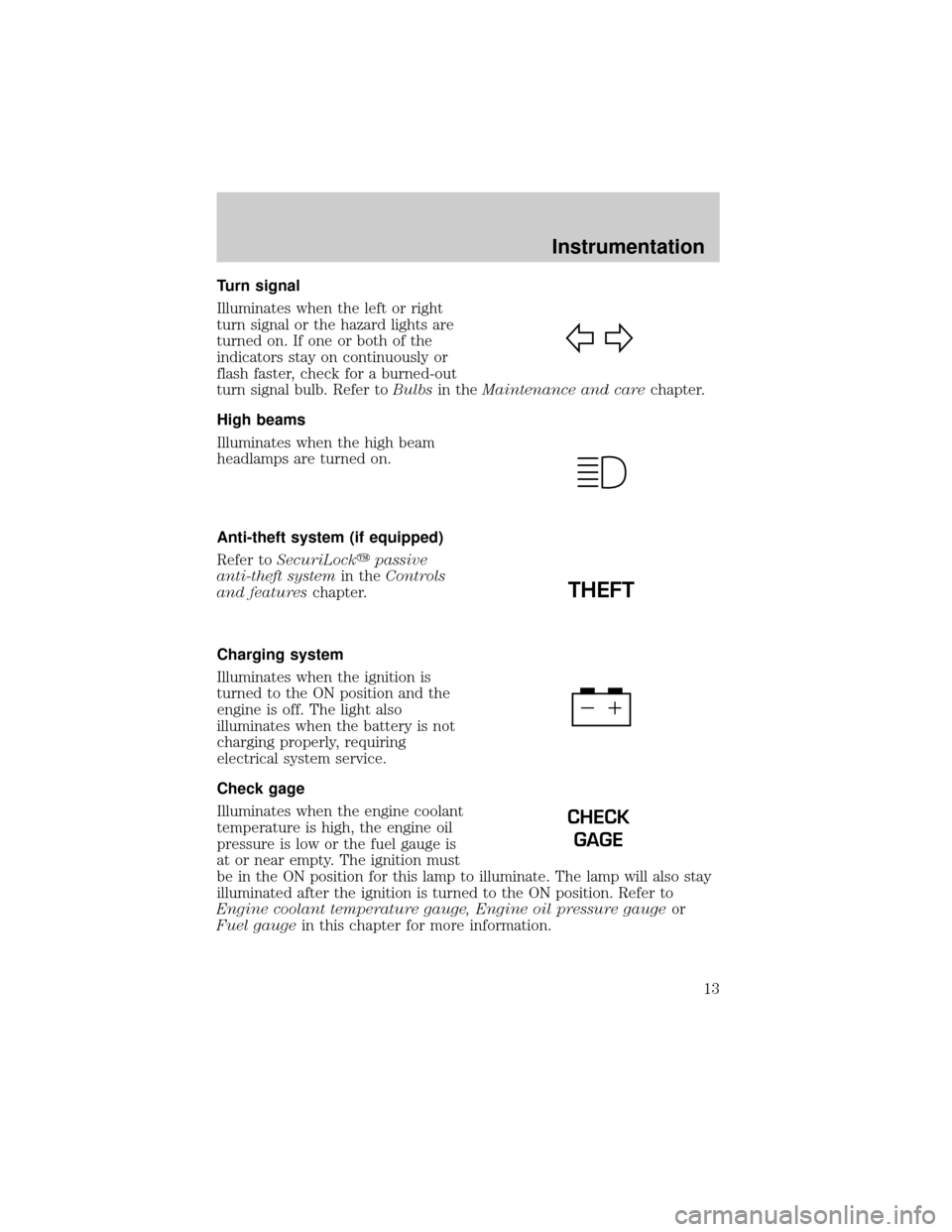
Turn signal
Illuminates when the left or right
turn signal or the hazard lights are
turned on. If one or both of the
indicators stay on continuously or
flash faster, check for a burned-out
turn signal bulb. Refer toBulbsin theMaintenance and carechapter.
High beams
Illuminates when the high beam
headlamps are turned on.
Anti-theft system (if equipped)
Refer toSecuriLockypassive
anti-theft systemin theControls
and featureschapter.
Charging system
Illuminates when the ignition is
turned to the ON position and the
engine is off. The light also
illuminates when the battery is not
charging properly, requiring
electrical system service.
Check gage
Illuminates when the engine coolant
temperature is high, the engine oil
pressure is low or the fuel gauge is
at or near empty. The ignition must
be in the ON position for this lamp to illuminate. The lamp will also stay
illuminated after the ignition is turned to the ON position. Refer to
Engine coolant temperature gauge, Engine oil pressure gaugeor
Fuel gaugein this chapter for more information.
THEFT
CHECK
GAGE
Instrumentation
13
Page 17 of 256
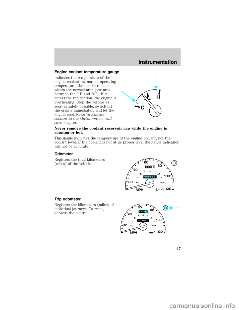
Engine coolant temperature gauge
Indicates the temperature of the
engine coolant. At normal operating
temperature, the needle remains
within the normal area (the area
between the ªHº and ªCº). If it
enters the red section, the engine is
overheating. Stop the vehicle as
soon as safely possible, switch off
the engine immediately and let the
engine cool. Refer toEngine
coolantin theMaintenance and
carechapter.
Never remove the coolant reservoir cap while the engine is
running or hot.
This gauge indicates the temperature of the engine coolant, not the
coolant level. If the coolant is not at its proper level the gauge indication
will not be accurate.
Odometer
Registers the total kilometers
(miles) of the vehicle.
Trip odometer
Registers the kilometers (miles) of
individual journeys. To reset,
depress the control.
C
H
MPH 2060
4080
km/h
00
1
20
160100
140
180
20
MPH 2060
4080
km/h
00
1
20
160100
140
180
20
Instrumentation
17
Page 18 of 256
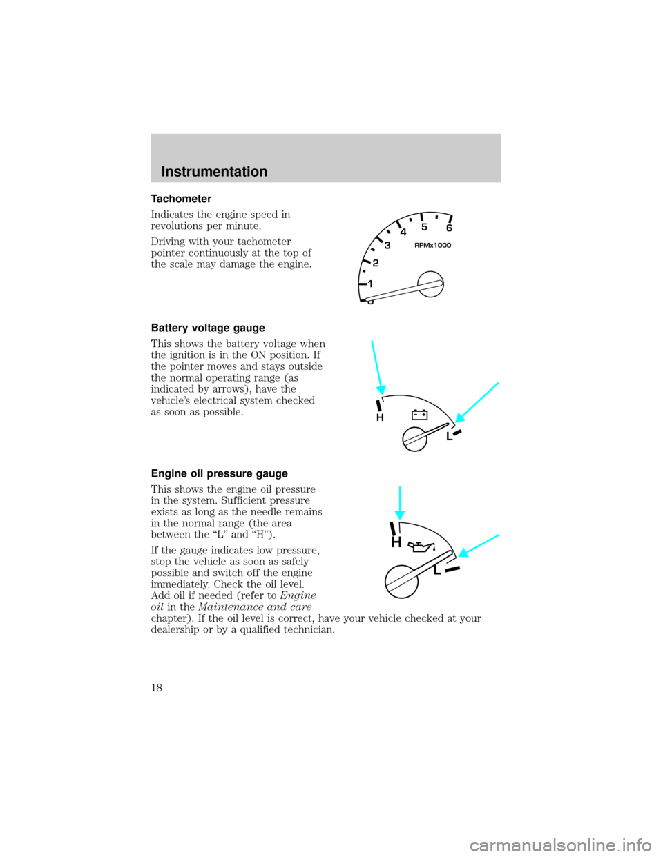
Tachometer
Indicates the engine speed in
revolutions per minute.
Driving with your tachometer
pointer continuously at the top of
the scale may damage the engine.
Battery voltage gauge
This shows the battery voltage when
the ignition is in the ON position. If
the pointer moves and stays outside
the normal operating range (as
indicated by arrows), have the
vehicle's electrical system checked
as soon as possible.
Engine oil pressure gauge
This shows the engine oil pressure
in the system. Sufficient pressure
exists as long as the needle remains
in the normal range (the area
between the ªLº and ªHº).
If the gauge indicates low pressure,
stop the vehicle as soon as safely
possible and switch off the engine
immediately. Check the oil level.
Add oil if needed (refer toEngine
oilin theMaintenance and care
chapter). If the oil level is correct, have your vehicle checked at your
dealership or by a qualified technician.
0 12345
6
RPMx1000
L
H
H
L
Instrumentation
18
Page 102 of 256
6. Within seven seconds of the safety belt warning light turning off,
buckle then unbuckle the safety belt.
²This will disable Belt Minder if it is currently enabled, or enable Belt
Minder if it is currently disabled.
7. Confirmation of disabling Belt Minder is provided by the safety belt
warning light flashing four times per second for three seconds.
8. Confirmation of enabling Belt Minder is provided by:
²The safety belt warning light flashing four times per second for three
seconds.
²Followed by three seconds with the safety belt warning light off.
²Once again, the safety belt warning light will flash four times per
second for three seconds.
9. After receiving confirmation, the deactivation/activation procedure is
complete.
Safety belt maintenance
Inspect the safety belt systems periodically to make sure they work
properly and are not damaged. Inspect the safety belts to make sure
there are no nicks, tears or cuts. Replace if necessary. All safety belt
assemblies, including retractors, buckles, front seat belt buckle
assemblies, buckle support assemblies (slide bar-if equipped), shoulder
belt height adjusters (if equipped), shoulder belt guide on seatback (if
equipped), child safety seat tether bracket assemblies (if equipped),
LATCH child seat tether anchors and lower anchors (if equipped), and
attaching hardware, should be inspected after a collision. Ford
recommends that all safety belt assemblies used in vehicles involved in a
collision be replaced. However, if the collision was minor and a qualified
technician finds that the belts do not show damage and continue to
operate properly, they do not need to be replaced. Safety belt assemblies
not in use during a collision should also be inspected and replaced if
either damage or improper operation is noted.
Failure to inspect and if necessary replace the safety belt
assembly under the above conditions could result in severe
personal injuries in the event of a collision.
Refer toCleaning and maintaining the safety beltsin the
Maintenacne and Caresection.
Seating and safety restraints
102
Page 108 of 256
Several air bag system components get hot after inflation. Do not
touch them after inflation.
If the air bag has deployed,the air bag will not function
again and must be replaced immediately.If the air bag is not
replaced, the unrepaired area will increase the risk of injury in a
collision.
Determining if the system is operational
The SRS uses a readiness light in the instrument cluster or a tone to
indicate the condition of the system. Refer to theAir bag readiness
section in theInstrumentationchapter. Routine maintenance of the air
bag is not required.
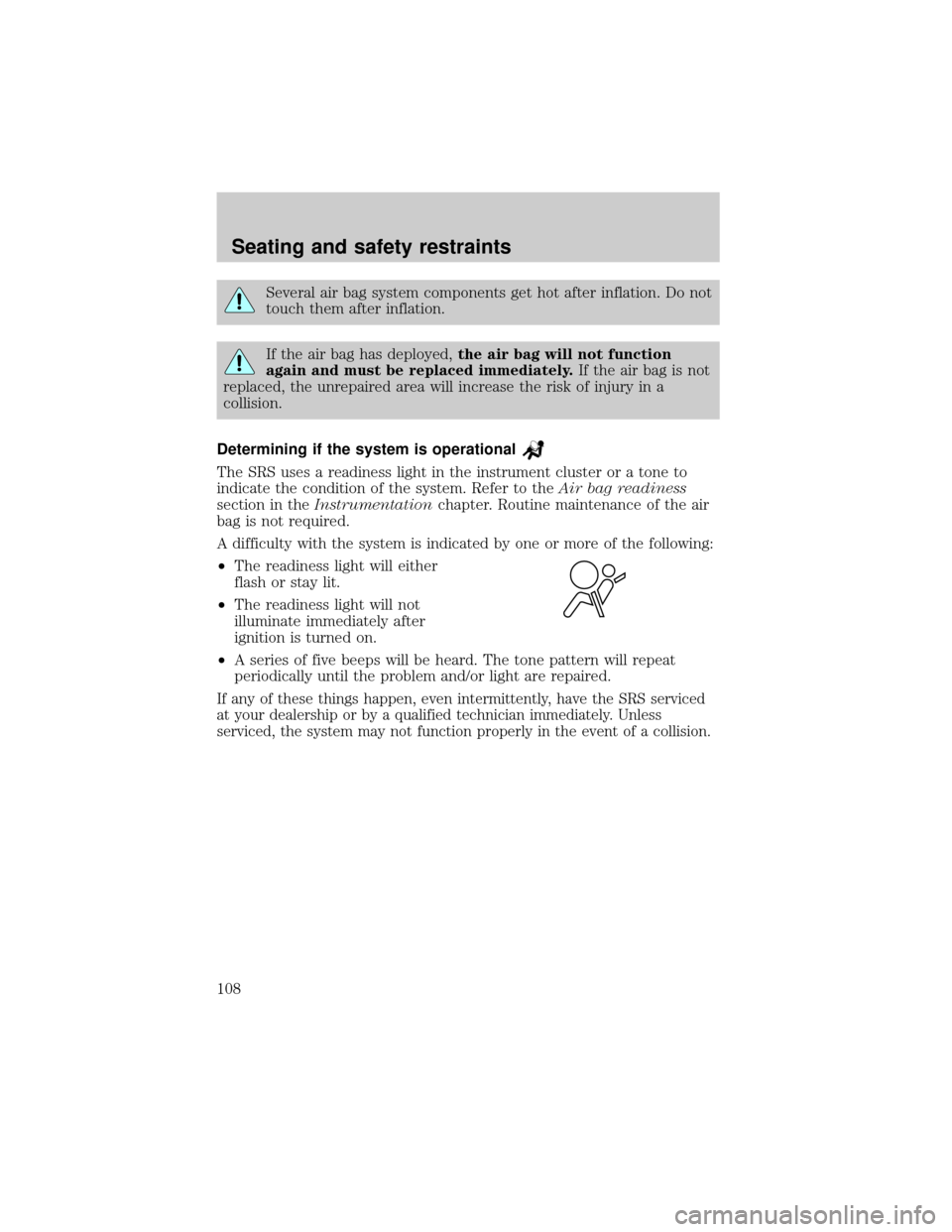
A difficulty with the system is indicated by one or more of the following:
²The readiness light will either
flash or stay lit.
²The readiness light will not
illuminate immediately after
ignition is turned on.
²A series of five beeps will be heard. The tone pattern will repeat
periodically until the problem and/or light are repaired.
If any of these things happen, even intermittently, have the SRS serviced
at your dealership or by a qualified technician immediately. Unless
serviced, the system may not function properly in the event of a collision.
Seating and safety restraints
108
Page 111 of 256
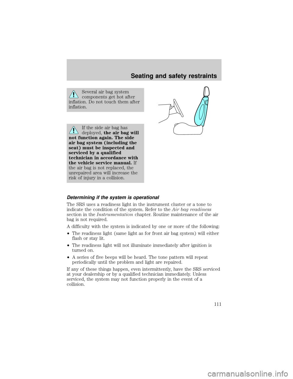
Several air bag system
components get hot after
inflation. Do not touch them after
inflation.
If the side air bag has
deployed,the air bag will
not function again. The side
air bag system (including the
seat) must be inspected and
serviced by a qualified
technician in accordance with
the vehicle service manual.If
the air bag is not replaced, the
unrepaired area will increase the
risk of injury in a collision.
Determining if the system is operational
The SRS uses a readiness light in the instrument cluster or a tone to
indicate the condition of the system. Refer to theAir bag readiness
section in theInstrumentationchapter. Routine maintenance of the air
bag is not required.
A difficulty with the system is indicated by one or more of the following:
²The readiness light (same light as for front air bag system) will either
flash or stay lit.
²The readiness light will not illuminate immediately after ignition is
turned on.
²A series of five beeps will be heard. The tone pattern will repeat
periodically until the problem and light are repaired.
If any of these things happen, even intermittently, have the SRS serviced
at your dealership or by a qualified technician immediately. Unless
serviced, the system may not function properly in the event of a
collision.
Seating and safety restraints
111
Page 125 of 256
BRAKES
Your service brakes are self-adjusting. Refer to the scheduled
maintenance guide for scheduled maintenance.
Occasional brake noise is normal and often does not indicate a
performance concern with the vehicle's brake system. In normal
operation, automotive brake systems may emit occasional or intermittent
squeal or groan noises when the brakes are applied. Such noises are
usually heard during the first few brake applications in the morning;
however, they may be heard at any time while braking and can be
aggravated by environmental conditions such as cold, heat, moisture,
road dust, salt or mud. If a ªmetal-to-metal,º ªcontinuous grindingº or
ªcontinuous squealº sound is present while braking, the brake linings
may be worn-out and should be inspected by a qualified service
technician.
Four-wheel anti-lock brake system (ABS)
This vehicle is equipped with an anti-lock braking system (ABS). A noise
from the hydraulic pump motor and pulsation in the pedal may be
observed during ABS braking events. Pedal pulsation coupled with noise
while braking under panic conditions or on loose gravel, bumps, wet or
snowy roads is normal and indicates proper functioning of the vehicle's
anti-lock brake system. If the vehicle has continuous vibration or shudder
in the steering wheel while braking, the vehicle should be inspected by a
qualified service technician.
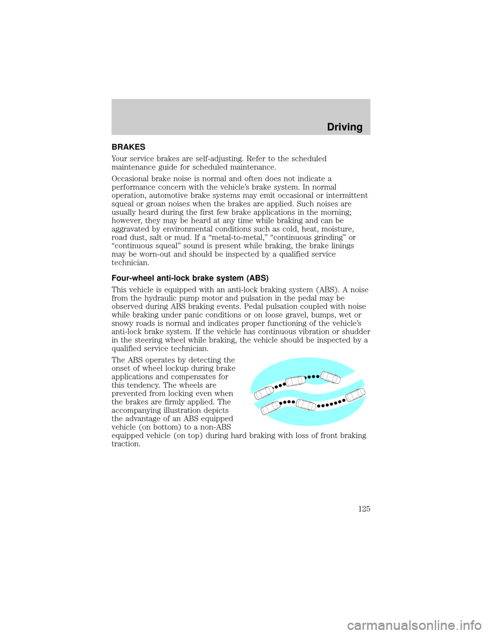
The ABS operates by detecting the
onset of wheel lockup during brake
applications and compensates for
this tendency. The wheels are
prevented from locking even when
the brakes are firmly applied. The
accompanying illustration depicts
the advantage of an ABS equipped
vehicle (on bottom) to a non-ABS
equipped vehicle (on top) during hard braking with loss of front braking
traction.
Driving
125
Page 144 of 256
²Thoroughly prepare your vehicle for towing. Refer toPreparing to
towin this chapter.
²Use extra caution when driving while trailer towing. Refer toDriving
while you towin this chapter.
²Service your vehicle more frequently if you tow a trailer. Refer to the
severe duty schedule in the scheduled maintenance guide.
²Do not tow a trailer until your vehicle has been driven at least 800 km
(500 miles).
²Refer to the instructions included with towing accessories for the
proper installation and adjustment specifications.
Do not exceed the maximum loads listed on the Safety Compliance
Certification label. For load specification terms found on the label, refer
toVehicle loadingin this chapter. Remember to figure in the tongue
load of your loaded vehicle when figuring the total weight.
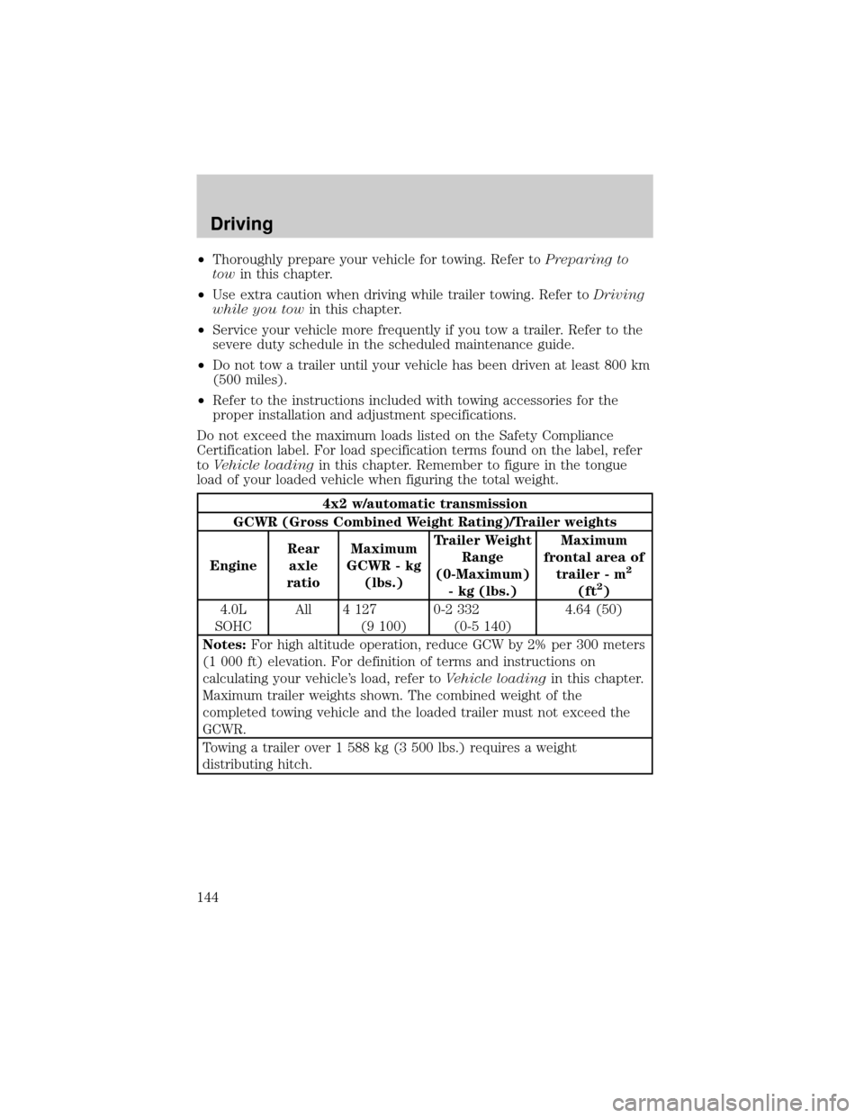
4x2 w/automatic transmission
GCWR (Gross Combined Weight Rating)/Trailer weights
EngineRear
axle
ratioMaximum
GCWR - kg
(lbs.)Trailer Weight
Range
(0-Maximum)
- kg (lbs.)Maximum
frontal area of
trailer - m
2
(ft2)
4.0L
SOHCAll 4 127
(9 100)0-2 332
(0-5 140)4.64 (50)
Notes:For high altitude operation, reduce GCW by 2% per 300 meters
(1 000 ft) elevation. For definition of terms and instructions on
calculating your vehicle's load, refer toVehicle loadingin this chapter.
Maximum trailer weights shown. The combined weight of the
completed towing vehicle and the loaded trailer must not exceed the
GCWR.
Towing a trailer over 1 588 kg (3 500 lbs.) requires a weight
distributing hitch.
Driving
144