FORD F-150 2020 Owners Manual
Manufacturer: FORD, Model Year: 2020, Model line: F-150, Model: FORD F-150 2020Pages: 625, PDF Size: 7.98 MB
Page 281 of 625
Radar Troubleshooting (If Equipped)
Action
Cause
Clean the grille surface in front of the radaror remove the object causing the obstruc- tion.
The surface of the radar in the grille is dirty
or obstructed in some way.
Wait a short time. It may take several
minutes for the radar to detect that there is no obstruction.
The surface of the radar in the grille is clean
but the message remains in the display screen.
The Pre-Collision Assist system is tempor-
arily disabled. Pre-Collision Assist automat-ically reactivates a short time after the weather conditions improve.
Heavy rain, spray, snow or fog is interfering
with the radar signals.
The Pre-Collision Assist system is tempor-
arily disabled. Pre-Collision Assist automat-ically reactivates a short time after the weather conditions improve.
Swirling water or snow or ice on the surface
of the road may interfere with the radar signals.
Contact an authorized dealer to have theradar checked for proper coverage and operation.
Radar is out of alignment due to a front end
impact.
Note: Proper system operation requires a
clear view of the road by the camera. Have
any windshield damage in the area of the
camera's field of view repaired.
Note: If something hits the front end of your
vehicle or damage occurs and your vehicle
has a radar sensor, the radar sensing zone
may change. This could cause missed or
false vehicle detections. Contact an
authorized dealer to have the radar checked
for proper coverage and operation.
Note: If your vehicle detects excessive heat
at the camera or a potential misalignment
condition, a message may display in the
information display indicating temporary
sensor unavailability. When operational
conditions are correct, the message
deactivates. For example, when the ambient
temperature around the sensor decreases
or the sensor automatically recalibrates
successfully. DRIVE CONTROL
Selectable Drive Modes
This provides a single location to control
multiple system performance settings such
as steering, handling and powertrain
response.
Changing the drive mode automatically
changes the functionality of the following
systems:
278
F-150 (TFC) Canada/United States of America, enUSA, Edition date: 201907, Third-Printing- Driving Aids
Page 282 of 625
•
Electronic stability control and traction
control maintains your vehicle control
in adverse conditions or high
performance driving. See Stability
Control (page 238).
• Electronic throttle control enhances
the powertrain response to your inputs.
• Transmission controls are optimized
with shift schedules tuned to each
terrain.
Using the System
The system tailors your vehicle
configuration for each mode you select.
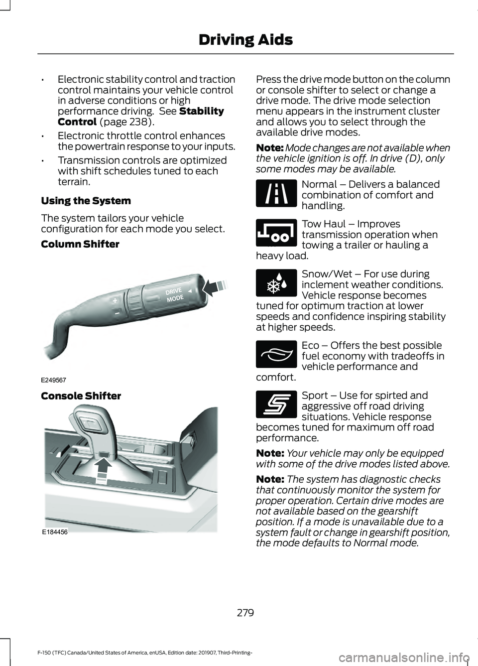
Column Shifter Console Shifter Press the drive mode button on the column
or console shifter to select or change a
drive mode. The drive mode selection
menu appears in the instrument cluster
and allows you to select through the
available drive modes.
Note:
Mode changes are not available when
the vehicle ignition is off. In drive (D), only
some modes may be available. Normal – Delivers a balanced
combination of comfort and
handling.
Tow Haul – Improves
transmission operation when
towing a trailer or hauling a
heavy load. Snow/Wet – For use during
inclement weather conditions.
Vehicle response becomes
tuned for optimum traction at lower
speeds and confidence inspiring stability
at higher speeds. Eco – Offers the best possible
fuel economy with tradeoffs in
vehicle performance and
comfort. Sport – Use for spirted and
aggressive off road driving
situations. Vehicle response
becomes tuned for maximum off road
performance.
Note: Your vehicle may only be equipped
with some of the drive modes listed above.
Note: The system has diagnostic checks
that continuously monitor the system for
proper operation. Certain drive modes are
not available based on the gearshift
position. If a mode is unavailable due to a
system fault or change in gearshift position,
the mode defaults to Normal mode.
279
F-150 (TFC) Canada/United States of America, enUSA, Edition date: 201907, Third-Printing- Driving AidsE249567 E184456 E225310 E246592 E225312 E295413 E246593
Page 283 of 625
Some drive modes reduce
traction and stability control
performance and the warning
indicator illuminates in the instrument
cluster. See Using Stability Control
(page 239).
280
F-150 (TFC) Canada/United States of America, enUSA, Edition date: 201907, Third-Printing- Driving AidsE130458
Page 284 of 625
LOAD RETAINING FIXTURES (IF
EQUIPPED)
BoxLink
™ Cleats
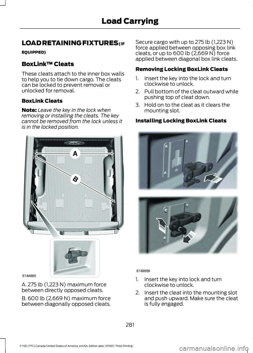
These cleats attach to the inner box walls
to help you to tie down cargo. The cleats
can be locked to prevent removal or
unlocked for removal.
BoxLink Cleats
Note: Leave the key in the lock when
removing or installing the cleats. The key
cannot be removed from the lock unless it
is in the locked position. A. 275 lb (1,223 N) maximum force
between directly opposed cleats.
B. 600 lb (2,669 N)
maximum force
between diagonally opposed cleats. Secure cargo with up to
275 lb (1,223 N)
force applied between opposing box link
cleats, or up to
600 lb (2,669 N) force
applied between diagonal box link cleats.
Removing Locking BoxLink Cleats
1. Insert the key into the lock and turn clockwise to unlock.
2. Pull bottom of the cleat outward while
pushing top of cleat down.
3. Hold on to the cleat as it clears the mounting slot.
Installing Locking BoxLink Cleats 1. Insert the key into lock and turn
clockwise to unlock.
2. Insert the cleat into the mounting slot and push upward. Make sure the cleat
is fully engaged.
281
F-150 (TFC) Canada/United States of America, enUSA, Edition date: 201907, Third-Printing- Load CarryingE184885 E189558
Page 285 of 625
3. Turn the key counterclockwise to lock.
4. Remove the key.
LOAD LIMIT
Vehicle Loading - with and
without a Trailer
This section guides you in the
proper loading of your vehicle,
trailer, or both. Keep your loaded
vehicle weight within its design
rating capability, with or without
a trailer. Properly loading your
vehicle provides maximum return
of vehicle design performance.
Before you load your vehicle,
become familiar with the
following terms for determining
your vehicle
’s weight rating, with
or without a trailer, from the
vehicle ’s Tire and Loading
Information label or Safety
Compliance Certification label. Tire and Loading Label Information
Example:
Payload
Payload is the combined weight
of cargo and passengers that your
vehicle is carrying. The maximum
payload for your vehicle appears
on the Tire and Loading label. The
label is either on the B-pillar or the
edge of the driver door. Vehicles
exported outside the US and
Canada may not have a tire and
loading label. Look for
“The
combined weight of occupants
and cargo should never exceed
XXX kg OR XXX lb ” for maximum
payload. The payload listed on the
Tire and Loading Information label
282
F-150 (TFC) Canada/United States of America, enUSA, Edition date: 201907, Third-Printing- Load CarryingE198719
Page 286 of 625
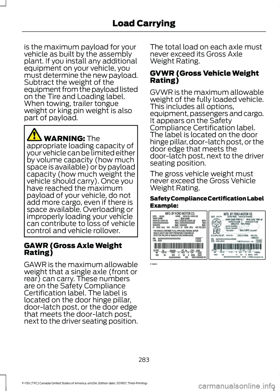
is the maximum payload for your
vehicle as built by the assembly
plant. If you install any additional
equipment on your vehicle, you
must determine the new payload.
Subtract the weight of the
equipment from the payload listed
on the Tire and Loading label.
When towing, trailer tongue
weight or king pin weight is also
part of payload.
WARNING: The
appropriate loading capacity of
your vehicle can be limited either
by volume capacity (how much
space is available) or by payload
capacity (how much weight the
vehicle should carry). Once you
have reached the maximum
payload of your vehicle, do not
add more cargo, even if there is
space available. Overloading or
improperly loading your vehicle
can contribute to loss of vehicle
control and vehicle rollover.
GAWR (Gross Axle Weight
Rating)
GAWR is the maximum allowable
weight that a single axle (front or
rear) can carry. These numbers
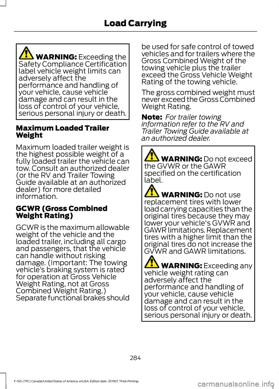
are on the Safety Compliance
Certification label. The label is
located on the door hinge pillar,
door-latch post, or the door edge
that meets the door-latch post,
next to the driver seating position. The total load on each axle must
never exceed its Gross Axle
Weight Rating.
GVWR (Gross Vehicle Weight
Rating)
GVWR is the maximum allowable
weight of the fully loaded vehicle.
This includes all options,
equipment, passengers and cargo.
It appears on the Safety
Compliance Certification label.
The label is located on the door
hinge pillar, door-latch post, or the
door edge that meets the
door-latch post, next to the driver
seating position.
The gross vehicle weight must
never exceed the Gross Vehicle
Weight Rating.
Safety Compliance Certification Label
Example:
283
F-150 (TFC) Canada/United States of America, enUSA, Edition date: 201907, Third-Printing- Load CarryingE198828
Page 287 of 625
WARNING: Exceeding the
Safety Compliance Certification
label vehicle weight limits can
adversely affect the
performance and handling of
your vehicle, cause vehicle
damage and can result in the
loss of control of your vehicle,
serious personal injury or death.
Maximum Loaded Trailer
Weight
Maximum loaded trailer weight is
the highest possible weight of a
fully loaded trailer the vehicle can
tow. Consult an authorized dealer
(or the RV and Trailer Towing
Guide available at an authorized
dealer) for more detailed
information.
GCWR (Gross Combined
Weight Rating)
GCWR is the maximum allowable
weight of the vehicle and the
loaded trailer, including all cargo
and passengers, that the vehicle
can handle without risking
damage. (Important: The towing
vehicle ’s braking system is rated
for operation at Gross Vehicle
Weight Rating, not at Gross
Combined Weight Rating.)
Separate functional brakes should be used for safe control of towed
vehicles and for trailers where the
Gross Combined Weight of the
towing vehicle plus the trailer
exceed the Gross Vehicle Weight
Rating of the towing vehicle.
The gross combined weight must
never exceed the Gross Combined
Weight Rating.
Note:
For trailer towing
information refer to the RV and
Trailer Towing Guide available at
an authorized dealer. WARNING:
Do not exceed
the GVWR or the GAWR
specified on the certification
label. WARNING:
Do not use
replacement tires with lower
load carrying capacities than the
original tires because they may
lower your vehicle's GVWR and
GAWR limitations. Replacement
tires with a higher limit than the
original tires do not increase the
GVWR and GAWR limitations. WARNING: Exceeding any
vehicle weight rating can
adversely affect the
performance and handling of
your vehicle, cause vehicle
damage and can result in the
loss of control of your vehicle,
serious personal injury or death.
284
F-150 (TFC) Canada/United States of America, enUSA, Edition date: 201907, Third-Printing- Load Carrying
Page 288 of 625
Steps for determining the
correct load limit:
1. Locate the statement "The
combined weight of occupants
and cargo should never exceed
XXX kg or XXX lb." on your
vehicle ’s placard.
2. Determine the combined
weight of the driver and
passengers that will be riding
in your vehicle.
3. Subtract the combined weight
of the driver and passengers
from XXX kg or XXX lb.
4. The resulting figure equals the
available amount of cargo and
luggage load capacity. For
example, if the “XXX” amount
equals 1,400 lb. and there will
be five 150 lb. passengers in
your vehicle, the amount of
available cargo and luggage
load capacity is 650 lb.
(1400-750 (5 x 150) = 650 lb.)
5. Determine the combined
weight of luggage and cargo
being loaded on the vehicle.
That weight may not safely
exceed the available cargo and
luggage load capacity
calculated in Step 4.
6. If your vehicle will be towing a
trailer, load from your trailer
will be transferred to your
vehicle. Consult this manual to
determine how this reduces the
available cargo and luggage
load capacity of your vehicle. Helpful examples for calculating
the available amount of cargo
and luggage load capacity
Suppose your vehicle has a
1400-pound (635-kilogram) cargo
and luggage capacity. You decide
to go golfing. Is there enough load
capacity to carry you, four of your
friends and all the golf bags? You
and four friends average 220
pounds (99 kilograms) each and
the golf bags weigh approximately
30 pounds (13.5 kilograms) each.
The calculation would be: 1400 -
(5 x 220) - (5 x 30) = 1400 - 1100
- 150 = 150 pounds. Yes, you have
enough load capacity in your
vehicle to transport four friends
and your golf bags. In metric units,
the calculation would be: 635
kilograms - (5 x 99 kilograms) -
(5 x 13.5 kilograms) = 635 - 495 -
67.5 = 72.5 kilograms.
Suppose your vehicle has a
1400-pound (635-kilogram) cargo
and luggage capacity. You and
one of your friends decide to pick
up cement from the local home
improvement store to finish that
patio you have been planning for
the past two years. Measuring the
inside of the vehicle with the rear
seat folded down, you have room
for twelve 100-pound
(45-kilogram) bags of cement. Do
you have enough load capacity to
transport the cement to your
home? If you and your friend each
weigh 220 pounds (99 kilograms),
the calculation would be: 1400 -
(2 x 220) - (12 x 100) = 1400 - 440
285
F-150 (TFC) Canada/United States of America, enUSA, Edition date: 201907, Third-Printing- Load Carrying
Page 289 of 625
- 1200 = - 240 pounds. No, you do
not have enough cargo capacity
to carry that much weight. In
metric units, the calculation would
be: 635 kilograms - (2 x 99
kilograms) - (12 x 45 kilograms) =
635 - 198 - 540 = -103 kilograms.
You will need to reduce the load
weight by at least 240 pounds
(104 kilograms). If you remove
three 100-pound (45-kilogram)
cement bags, then the load
calculation would be:1400 - (2 x
220) - (9 x 100) = 1400 - 440 -
900 = 60 pounds. Now you have
the load capacity to transport the
cement and your friend home. In
metric units, the calculation would
be: 635 kilograms - (2 x 99
kilograms) - (9 x 45 kilograms) =
635 - 198 - 405 = 32 kilograms.
The above calculations also
assume that the loads are
positioned in your vehicle in a
manner that does not overload
the front or the rear gross axle
weight rating specified for your
vehicle on the Safety Compliance
Certification label.
Special Loading Instructions
for Owners of Pick-up Trucks
and Utility-type Vehicles
WARNING: When loading
the roof racks, we recommend
you evenly distribute the load,
as well as maintain a low center
of gravity. Loaded vehicles, with
higher centers of gravity, may handle differently than unloaded
vehicles. Take extra precautions,
such as slower speeds and
increased stopping distance,
when driving a heavily loaded
vehicle.
BED ACCESS
(IF EQUIPPED)
Box Side Step
Use the step for easier access to the
vehicle bed.
Note: Close the step before driving.
Note: Do not exceed
500 lb (227 kg) on
the step. This includes you plus cargo.
Note: Do not use the step to lift the vehicle.
Only use proper jacking points.
Note: The step may operate more slowly
in cool temperatures.
Note: The step mechanism may trap debris
such as mud, dirt, snow, ice and salt. This
may prevent the step from deploying
automatically when you press the button.
If this happens, make sure that you press
the button down and carefully pull out the
step manually. Wash off the debris with a
high-pressure sprayer and stow the step.
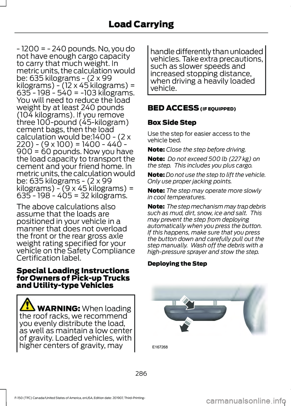
Deploying the Step 286
F-150 (TFC) Canada/United States of America, enUSA, Edition date: 201907, Third-Printing- Load CarryingE167268
Page 290 of 625
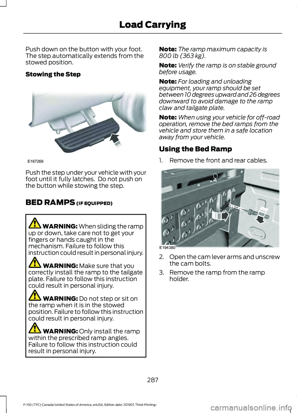
Push down on the button with your foot.
The step automatically extends from the
stowed position.
Stowing the Step
Push the step under your vehicle with your
foot until it fully latches. Do not push on
the button while stowing the step.
BED RAMPS (IF EQUIPPED)
WARNING:
When sliding the ramp
up or down, take care not to get your
fingers or hands caught in the
mechanism. Failure to follow this
instruction could result in personal injury. WARNING:
Make sure that you
correctly install the ramp to the tailgate
plate. Failure to follow this instruction
could result in personal injury. WARNING:
Do not step or sit on
the ramp when it is in the stowed
position. Failure to follow this instruction
could result in personal injury. WARNING:
Only install the ramp
within the prescribed ramp angles.
Failure to follow this instruction could
result in personal injury. Note:
The ramp maximum capacity is
800 lb (363 kg)
.
Note: Verify the ramp is on stable ground
before usage.
Note: For loading and unloading
equipment, your ramp should be set
between 10 degrees upward and 26 degrees
downward to avoid damage to the ramp
claw and tailgate plate.
Note: When using your vehicle for off-road
operation, remove the bed ramps from the
vehicle and store them in a safe location
away from your vehicle.
Using the Bed Ramp
1. Remove the front and rear cables. 2.
Open the cam lever arms and unscrew
the cam bolts.
3. Remove the ramp from the ramp holder.
287
F-150 (TFC) Canada/United States of America, enUSA, Edition date: 201907, Third-Printing- Load CarryingE167269 E194380