FORD F-150 2021 Owners Manual
Manufacturer: FORD, Model Year: 2021, Model line: F-150, Model: FORD F-150 2021Pages: 796, PDF Size: 13.89 MB
Page 571 of 796
Tire Change Procedure
WARNING: To help prevent your
vehicle from moving when changing a
wheel, shift the transmission into park
(P), set the parking brake and use an
appropriate block or wheel chock to
secure the wheel diagonally opposite to
the wheel being changed. For example,
when changing the front left wheel,
place an appropriate block or wheel
chock on the right rear wheel. WARNING:
The jack supplied with
this vehicle is only intended for changing
a flat tire in an emergency. Do not
attempt to do any other work on your
vehicle when it is supported by the jack,
as your vehicle could slip off the jack.
Failure to follow this instruction could
result in personal injury or death. WARNING:
Do not attempt to
change a tire on the side of the vehicle
close to moving traffic. Pull far enough
off the road to not obstruct the flow of
traffic and avoid the danger of being hit
when operating the jack or changing the
wheel. WARNING:
Only use the jack
provided as original equipment with your
vehicle. WARNING:
Do not get under a
vehicle that is supported by a jack. WARNING:
The jack supplied with
this vehicle is only intended for changing
a flat tire in an emergency. Do not
attempt to do any other work on your
vehicle when it is supported by the jack,
as your vehicle could slip off the jack.
Failure to follow this instruction could
result in personal injury or death. WARNING:
The jack should be
used on level firm ground wherever
possible. WARNING:
Never place anything
between the vehicle jack and the ground. WARNING:
Never place anything
between the vehicle jack and your
vehicle. WARNING: It is recommended that
the wheels of the vehicle be chocked,
and that no person should remain in a
vehicle that is being jacked. WARNING:
Switch off the running
boards before jacking or placing any
object under your vehicle. Never place
your hand between the extended running
board and your vehicle. A moving running
board may cause injury.
Park on a level surface, activate the hazard
flashers and set the parking brake. Then,
place the transmission in park (P) and turn
the engine off.
Note: Only use the spare tire carrier to stow
the tire and wheel combination provided
with your vehicle. Other tire and wheel
combinations can cause the tire carrier to
fail.
Note: Do not use impact tools or power
tools operating at over 200 RPM on the
spare tire carrier, this could cause a winch
malfunction and prevent a secure fit.
Note: Passengers should not remain in the
vehicle when the vehicle is being jacked.
Removing the Vehicle Jack and
Tool Bag
The vehicle jack and tool bag are on the
rear passenger side of your vehicle, behind
the passenger seat.
567
F-150 (TFD) Canada/United States of America, enUSA, Edition date: 202104, Second-Printing Changing a Road Wheel
Page 572 of 796
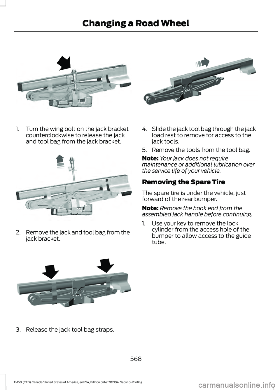
1. Turn the wing bolt on the jack bracket
counterclockwise to release the jack
and tool bag from the jack bracket. 2.
Remove the jack and tool bag from the
jack bracket. 3. Release the jack tool bag straps. 4.
Slide the jack tool bag through the jack
load rest to remove for access to the
jack tools.
5. Remove the tools from the tool bag.
Note: Your jack does not require
maintenance or additional lubrication over
the service life of your vehicle.
Removing the Spare Tire
The spare tire is under the vehicle, just
forward of the rear bumper.
Note: Remove the hook end from the
assembled jack handle before continuing.
1. Use your key to remove the lock cylinder from the access hole of the
bumper to allow access to the guide
tube.
568
F-150 (TFD) Canada/United States of America, enUSA, Edition date: 202104, Second-Printing Changing a Road WheelE323384 E327650 E323386 E327651
Page 573 of 796
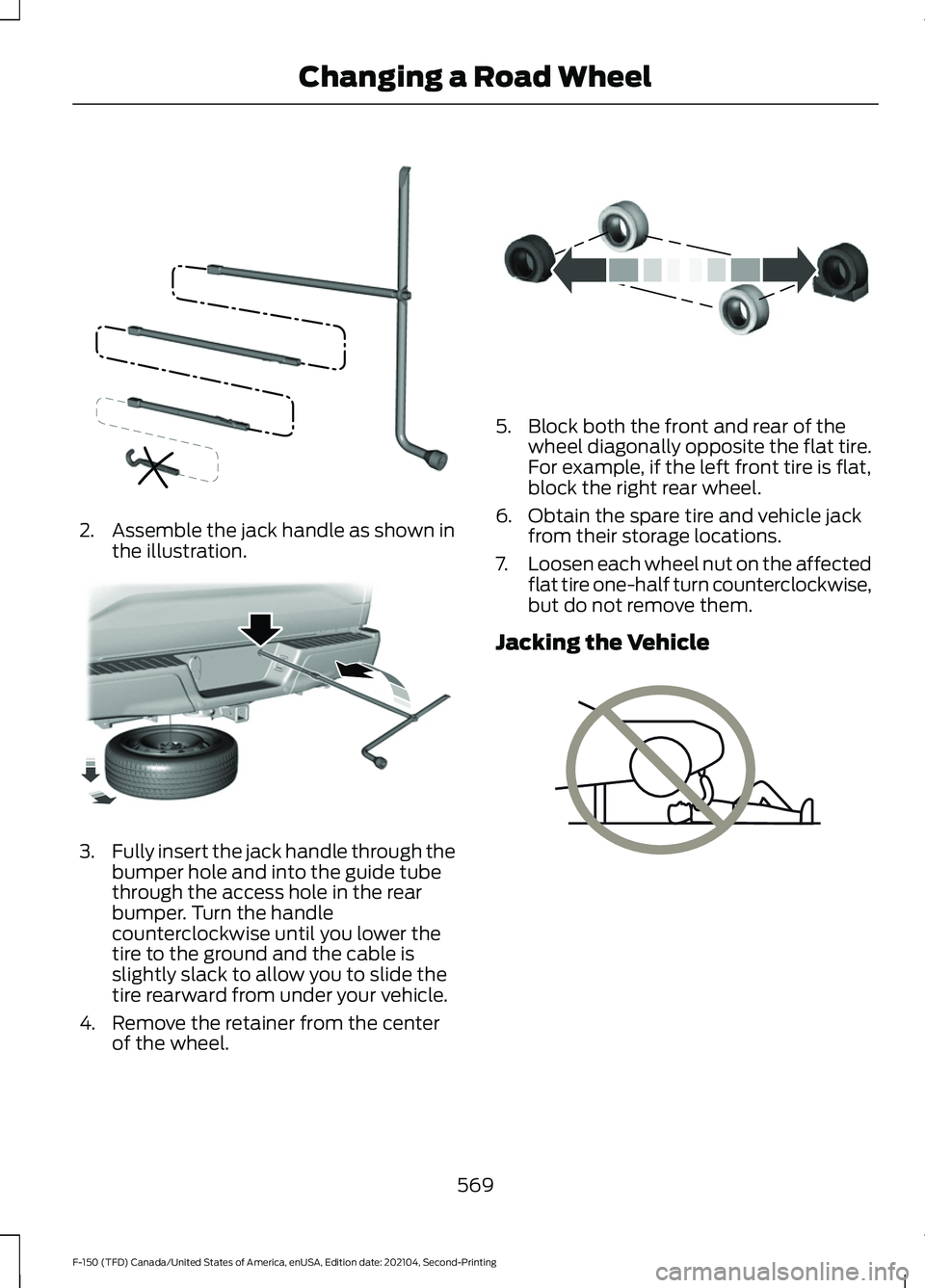
2. Assemble the jack handle as shown in
the illustration. 3.
Fully insert the jack handle through the
bumper hole and into the guide tube
through the access hole in the rear
bumper. Turn the handle
counterclockwise until you lower the
tire to the ground and the cable is
slightly slack to allow you to slide the
tire rearward from under your vehicle.
4. Remove the retainer from the center of the wheel. 5. Block both the front and rear of the
wheel diagonally opposite the flat tire.
For example, if the left front tire is flat,
block the right rear wheel.
6. Obtain the spare tire and vehicle jack from their storage locations.
7. Loosen each wheel nut on the affected
flat tire one-half turn counterclockwise,
but do not remove them.
Jacking the Vehicle 569
F-150 (TFD) Canada/United States of America, enUSA, Edition date: 202104, Second-Printing Changing a Road WheelE188735 E184020 E175447 E166722
Page 574 of 796
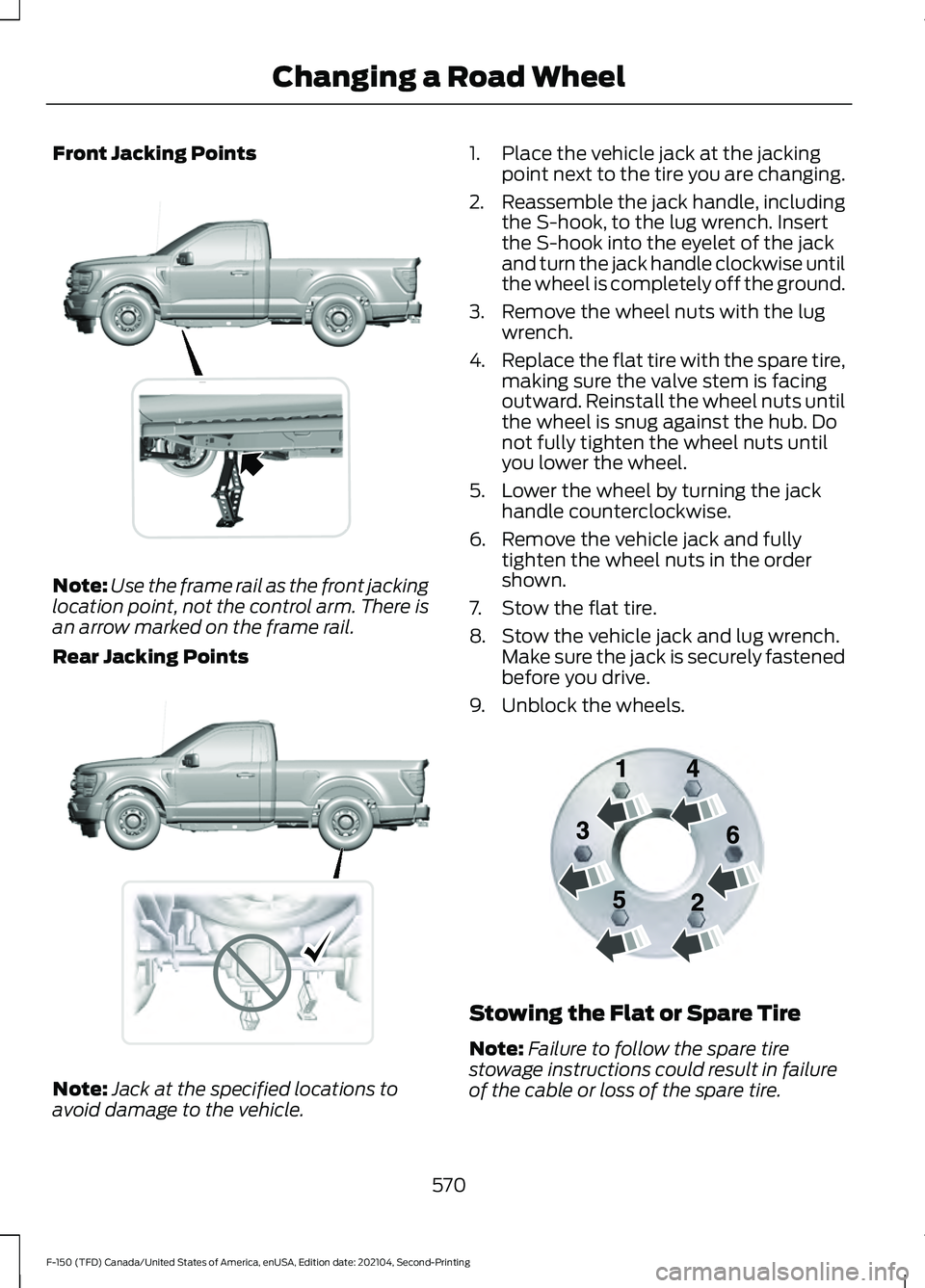
Front Jacking Points
Note:
Use the frame rail as the front jacking
location point, not the control arm. There is
an arrow marked on the frame rail.
Rear Jacking Points Note:
Jack at the specified locations to
avoid damage to the vehicle. 1. Place the vehicle jack at the jacking
point next to the tire you are changing.
2. Reassemble the jack handle, including
the S-hook, to the lug wrench. Insert
the S-hook into the eyelet of the jack
and turn the jack handle clockwise until
the wheel is completely off the ground.
3. Remove the wheel nuts with the lug wrench.
4. Replace the flat tire with the spare tire,
making sure the valve stem is facing
outward. Reinstall the wheel nuts until
the wheel is snug against the hub. Do
not fully tighten the wheel nuts until
you lower the wheel.
5. Lower the wheel by turning the jack handle counterclockwise.
6. Remove the vehicle jack and fully tighten the wheel nuts in the order
shown.
7. Stow the flat tire.
8. Stow the vehicle jack and lug wrench. Make sure the jack is securely fastened
before you drive.
9. Unblock the wheels. Stowing the Flat or Spare Tire
Note:
Failure to follow the spare tire
stowage instructions could result in failure
of the cable or loss of the spare tire.
570
F-150 (TFD) Canada/United States of America, enUSA, Edition date: 202104, Second-Printing Changing a Road Wheel E327652 E323397 E166719
Page 575 of 796
1. Lay the tire on the ground with the
valve stem facing up.
2. Slide the wheel partially under the vehicle and install the retainer through
the wheel center. Pull on the cable to
align the components at the end of the
cable.
3. Turn the jack handle clockwise until you raise the tire to its stowed position
underneath the vehicle. The effort to
turn the jack handle increases
significantly and the spare tire carrier
ratchets or slips when you raise the tire
to the maximum tightness. Tighten to
the point where the ratchet or slip
occurs a minimum of three times, as
indicated by an audible click each time.
The spare tire carrier does not allow
you to overtighten. If the spare tire
carrier ratchets or slips with little effort,
have your vehicle checked as soon as
possible.
4. Check that the tire lies flat against the frame and you properly tighten it. Try
to push or pull, then turn the tire to be
sure it does not move. Loosen and
retighten, if necessary. Failure to
properly stow the spare tire could
result in failure of the winch cable and
loss of the tire.
5. Repeat this tightness check procedure
when servicing the spare tire pressure,
every six months, as per your scheduled
maintenance information, or at any
time that the spare tire gets disturbed
through service of other components.
6. If removed, install the spare tire lock into the bumper drive tube with the
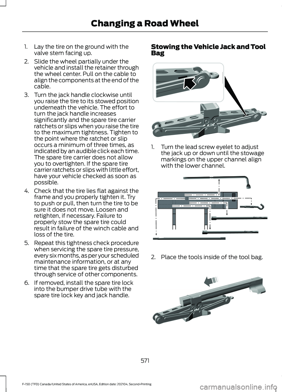
spare tire lock key and jack handle. Stowing the Vehicle Jack and Tool
Bag
1. Turn the lead screw eyelet to adjust
the jack up or down until the stowage
markings on the upper channel align
with the lower channel. 2. Place the tools inside of the tool bag.
571
F-150 (TFD) Canada/United States of America, enUSA, Edition date: 202104, Second-Printing Changing a Road Wheel E323394 E323393 E327653
Page 576 of 796
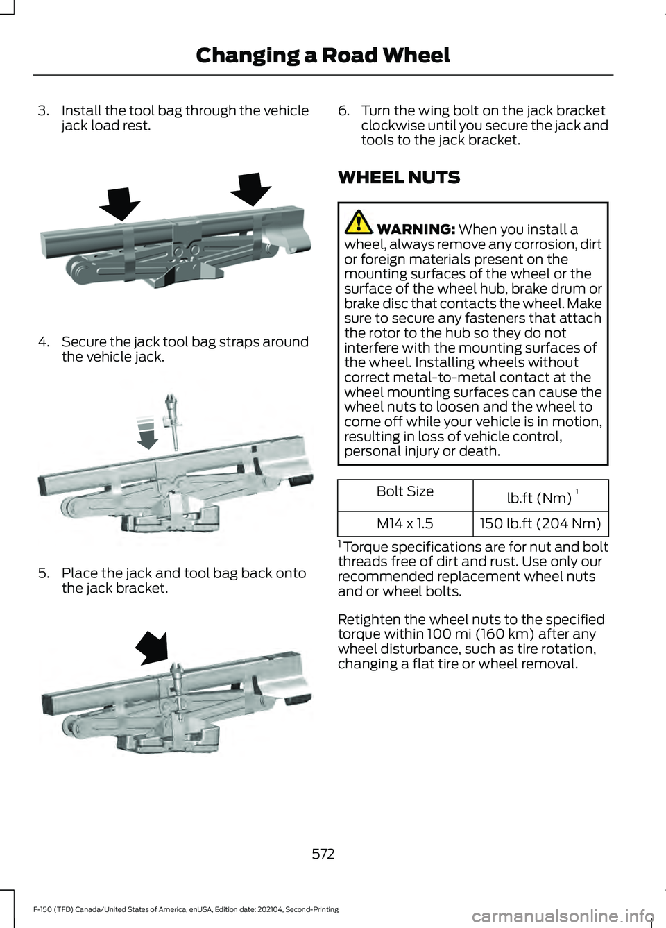
3.
Install the tool bag through the vehicle
jack load rest. 4.
Secure the jack tool bag straps around
the vehicle jack. 5. Place the jack and tool bag back onto
the jack bracket. 6. Turn the wing bolt on the jack bracket
clockwise until you secure the jack and
tools to the jack bracket.
WHEEL NUTS WARNING: When you install a
wheel, always remove any corrosion, dirt
or foreign materials present on the
mounting surfaces of the wheel or the
surface of the wheel hub, brake drum or
brake disc that contacts the wheel. Make
sure to secure any fasteners that attach
the rotor to the hub so they do not
interfere with the mounting surfaces of
the wheel. Installing wheels without
correct metal-to-metal contact at the
wheel mounting surfaces can cause the
wheel nuts to loosen and the wheel to
come off while your vehicle is in motion,
resulting in loss of vehicle control,
personal injury or death. lb.ft (Nm)
1
Bolt Size
150 lb.ft (204 Nm)
M14 x 1.5
1 Torque specifications are for nut and bolt
threads free of dirt and rust. Use only our
recommended replacement wheel nuts
and or wheel bolts.
Retighten the wheel nuts to the specified
torque within
100 mi (160 km) after any
wheel disturbance, such as tire rotation,
changing a flat tire or wheel removal.
572
F-150 (TFD) Canada/United States of America, enUSA, Edition date: 202104, Second-Printing Changing a Road WheelE323386 E327654 E323384
Page 577 of 796
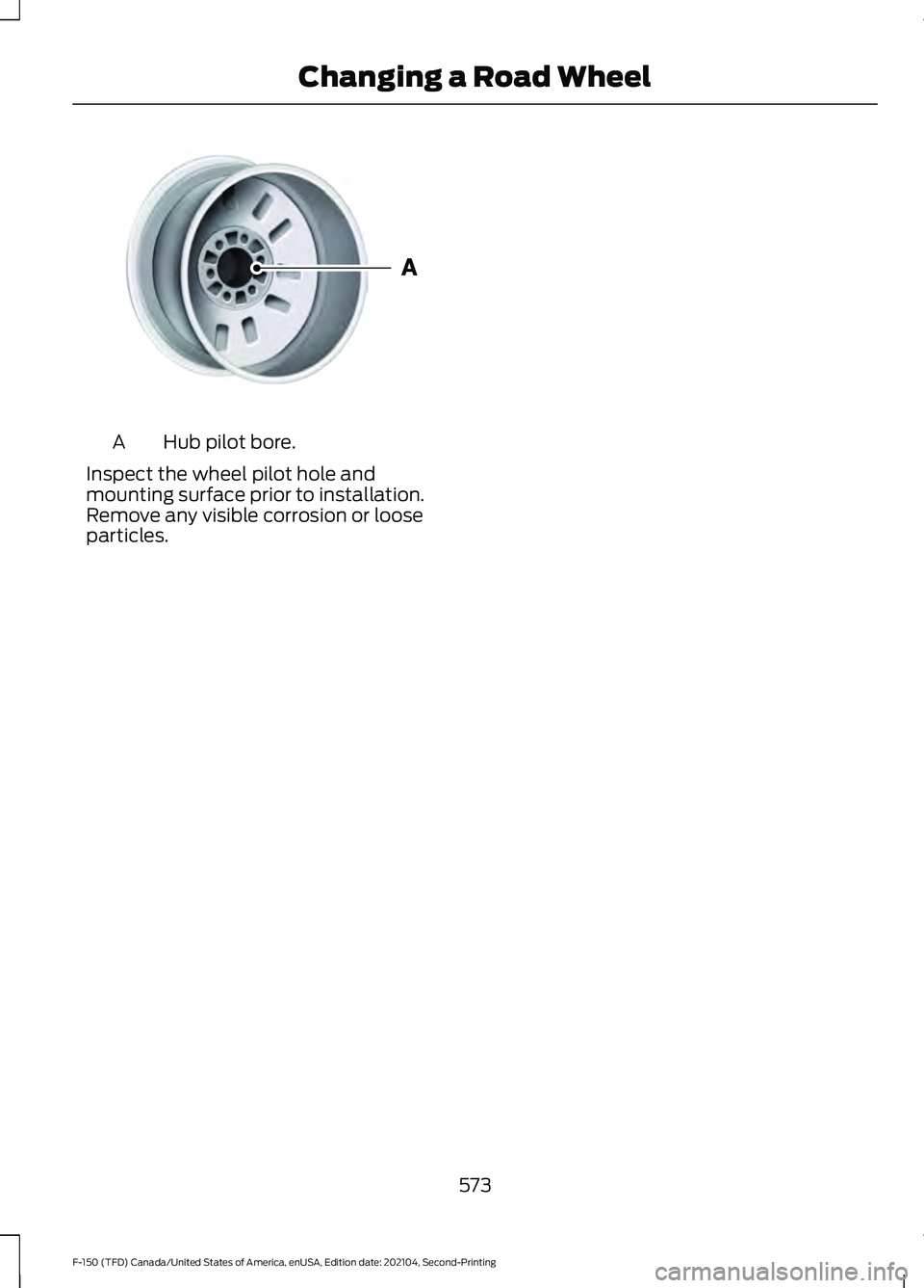
Hub pilot bore.
A
Inspect the wheel pilot hole and
mounting surface prior to installation.
Remove any visible corrosion or loose
particles.
573
F-150 (TFD) Canada/United States of America, enUSA, Edition date: 202104, Second-Printing Changing a Road WheelE145950
Page 578 of 796
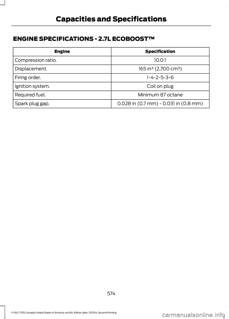
ENGINE SPECIFICATIONS - 2.7L ECOBOOST™
Specification
Engine
10.0:1
Compression ratio.
165 in³ (2,700 cm³)
Displacement.
1-4-2-5-3-6
Firing order.
Coil on plug
Ignition system.
Minimum 87 octane
Required fuel.
0.028 in (0.7 mm) - 0.031 in (0.8 mm)
Spark plug gap.
574
F-150 (TFD) Canada/United States of America, enUSA, Edition date: 202104, Second-Printing Capacities and Specifications
Page 579 of 796
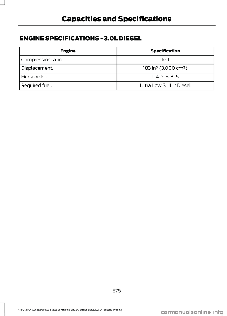
ENGINE SPECIFICATIONS - 3.0L DIESEL
Specification
Engine
16:1
Compression ratio.
183 in³ (3,000 cm³)
Displacement.
1-4-2-5-3-6
Firing order.
Ultra Low Sulfur Diesel
Required fuel.
575
F-150 (TFD) Canada/United States of America, enUSA, Edition date: 202104, Second-Printing Capacities and Specifications
Page 580 of 796
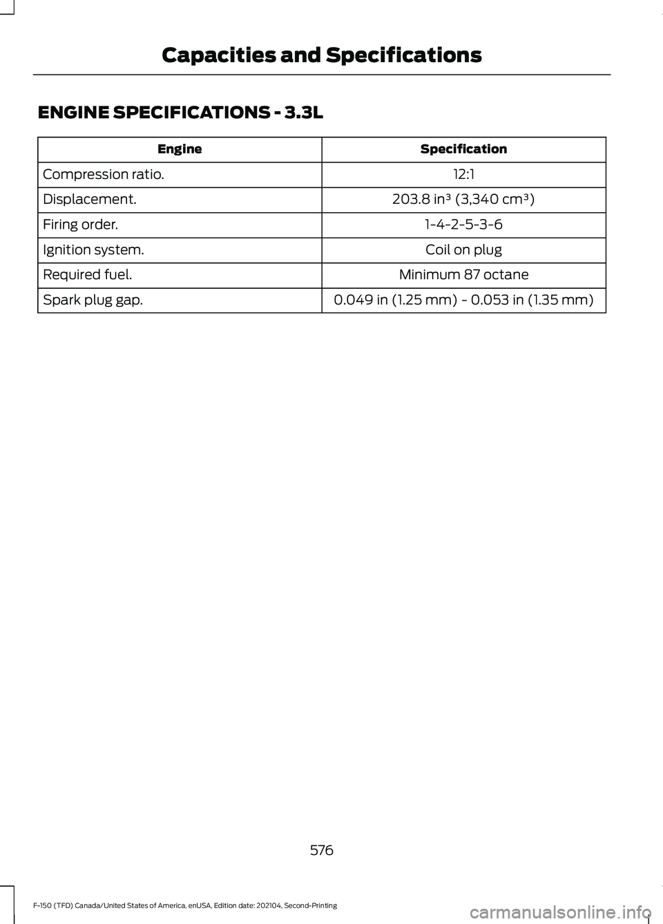
ENGINE SPECIFICATIONS - 3.3L
Specification
Engine
12:1
Compression ratio.
203.8 in³ (3,340 cm³)
Displacement.
1-4-2-5-3-6
Firing order.
Coil on plug
Ignition system.
Minimum 87 octane
Required fuel.
0.049 in (1.25 mm) - 0.053 in (1.35 mm)
Spark plug gap.
576
F-150 (TFD) Canada/United States of America, enUSA, Edition date: 202104, Second-Printing Capacities and Specifications