lock FORD F-250 2019 Owners Manual
[x] Cancel search | Manufacturer: FORD, Model Year: 2019, Model line: F-250, Model: FORD F-250 2019Pages: 666, PDF Size: 13.6 MB
Page 265 of 666
Extreme continuous steering may increase
the effort required for you to steer your
vehicle. This increased effort prevents
overheating and permanent damage to
the steering system. You do not lose the
ability to steer your vehicle manually.
Typical steering and driving maneuvers
allow the system to cool and return to
normal operation.
Adaptive Learning (If Equipped)
The electronic power steering system
adaptive learning helps correct road
irregularities and improves overall handling
and steering feel. It communicates with
the brake system to help operate
advanced stability control and accident
avoidance systems. Whenever the battery
is disconnected or a new battery installed,
you must drive your vehicle a short
distance before the system relearns the
strategy and reactivates all systems.
Adaptive Steering
(If Equipped)
Note: The adaptive steering system has
diagnostic checks that continuously monitor
the system. If the system detects a fault, a
message displays in the information display.
If a red warning message displays, stop your
vehicle as soon as it is safe to do so. The
message may clear if the fault is no longer
present. If an adaptive steering system
warning message appears each time you
start your vehicle, have the system checked
as soon as possible.
The adaptive steering system continually
changes the steering ratio with changes to
vehicle speed, optimizing the steering
response in all conditions. The system also
changes when you switch on the
transmission tow/haul feature. When you
select the tow/haul button, the adaptive
steering system reduces vehicle sensitivity
to steering inputs at higher vehicle speeds,
while maintaining the ease of parking and
maneuverability at low speeds. Note:
The adaptive steering system is
designed with a locking device. With the
lock engaged, the adaptive steering system
remains mechanically locked at a fixed
steering ratio. You may also notice a click
when you switch the vehicle on or after you
switch it off, as the lock disengages or
engages.
Note: If your vehicle loses electrical power
or detects a fault when you are driving, the
system automatically shuts down and you
retain normal steering function with a fixed
steering ratio. During this time it is possible
that the steering wheel may not be straight
when the vehicle is driving straight ahead.
In addition, the driver may notice that the
steering wheel angle required to steer the
vehicle may be different.
Note: During parking maneuvers, the
adaptive steering system balances the driver
work load for various steering wheel inputs
and vehicle loading conditions. Under
extreme operating conditions the system
locking device may engage. This strategy
prevents overheating and permanent
damage to the adaptive steering system.
Typical steering and driving maneuvers
allow the system to cool and return to
normal operation.
PRE-COLLISION ASSIST
(IF
EQUIPPED) WARNING:
You are responsible
for controlling your vehicle at all times.
The system is designed to be an aid and
does not relieve you of your responsibility
to drive with due care and attention.
Failure to follow this instruction could
result in the loss of control of your
vehicle, personal injury or death.
262
Super Duty (TFE) Canada/United States of America, enUSA, Edition date: 201804, Fourth-Printing Driving Aids
Page 266 of 666
WARNING: This system is an extra
driving aid. It does not replace your
attention and judgment, or the need to
apply the brakes. This system does NOT
automatically brake your vehicle. If you
fail to press the brake pedal when
necessary, you may collide with another
vehicle. WARNING: The Pre-Collision
Assist system with brake support cannot
help prevent all collisions. Do not rely on
this system to replace your judgment
and the need to maintain correct
distance and speed. WARNING: The pre-collision assist
system's brake support reduces collision
speed only if you brake your vehicle
before any collision. You must press your
brake pedal as you would in any typical
braking situation.
Note: The system does not detect, warn or
respond to potential collisions with vehicles
to the rear or side of your vehicle.
Note: The system is active at speeds above
approximately
5 mph (8 km/h).
Note: The system becomes unavailable if
you disable the electronic stability control.
See
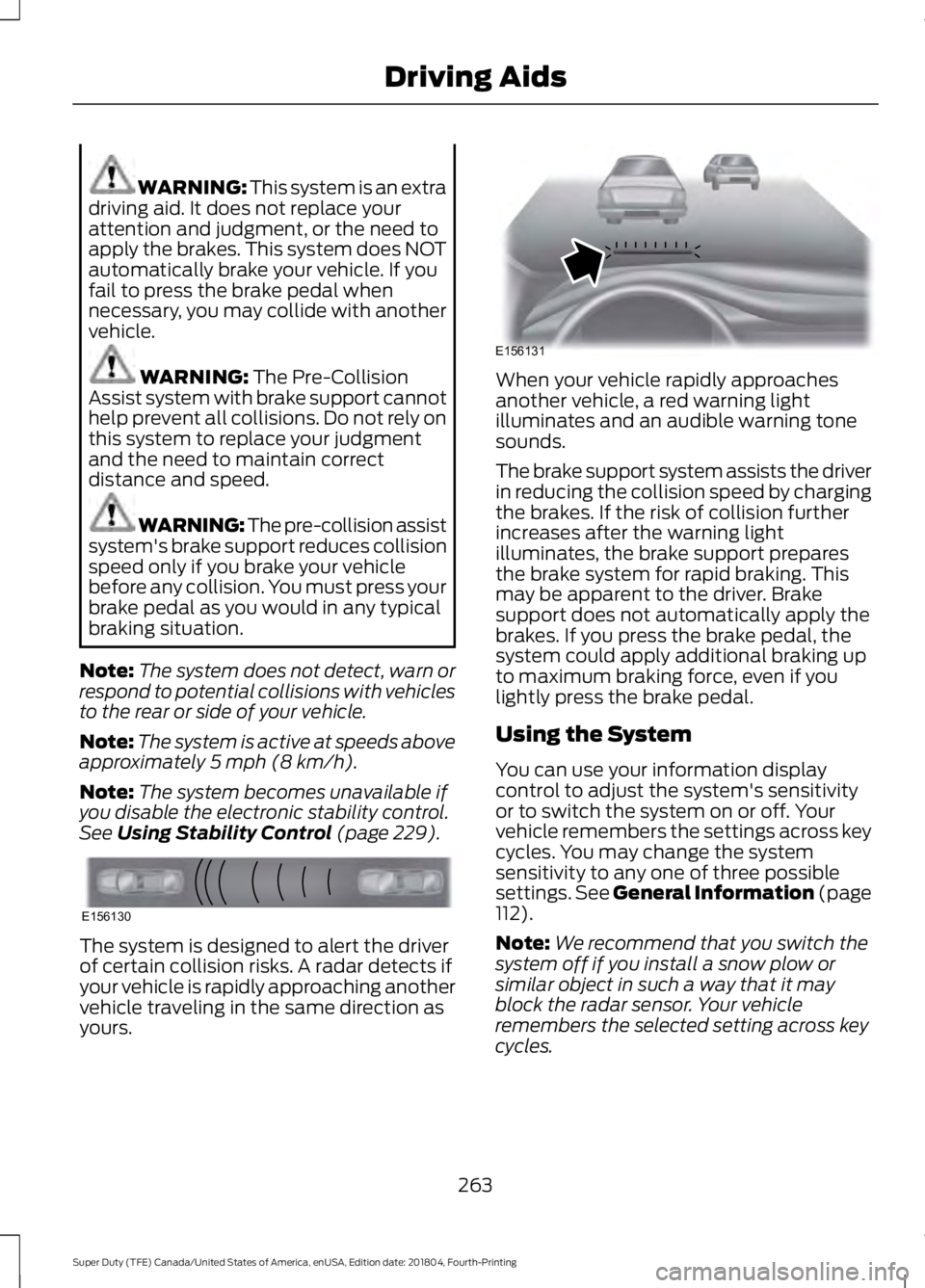
Using Stability Control (page 229). The system is designed to alert the driver
of certain collision risks. A radar detects if
your vehicle is rapidly approaching another
vehicle traveling in the same direction as
yours. When your vehicle rapidly approaches
another vehicle, a red warning light
illuminates and an audible warning tone
sounds.
The brake support system assists the driver
in reducing the collision speed by charging
the brakes. If the risk of collision further
increases after the warning light
illuminates, the brake support prepares
the brake system for rapid braking. This
may be apparent to the driver. Brake
support does not automatically apply the
brakes. If you press the brake pedal, the
system could apply additional braking up
to maximum braking force, even if you
lightly press the brake pedal.
Using the System
You can use your information display
control to adjust the system's sensitivity
or to switch the system on or off. Your
vehicle remembers the settings across key
cycles. You may change the system
sensitivity to any one of three possible
settings.
See General Information (page
112).
Note: We recommend that you switch the
system off if you install a snow plow or
similar object in such a way that it may
block the radar sensor. Your vehicle
remembers the selected setting across key
cycles.
263
Super Duty (TFE) Canada/United States of America, enUSA, Edition date: 201804, Fourth-Printing Driving AidsE156130 E156131
Page 267 of 666
Note:
If you perceive warnings being too
frequent or disturbing, you can reduce the
warning sensitivity, though the manufacturer
recommends using the highest sensitivity
setting where possible. Setting to a lower
sensitivity would lead to fewer and later
system warnings. See General Information
(page 112).
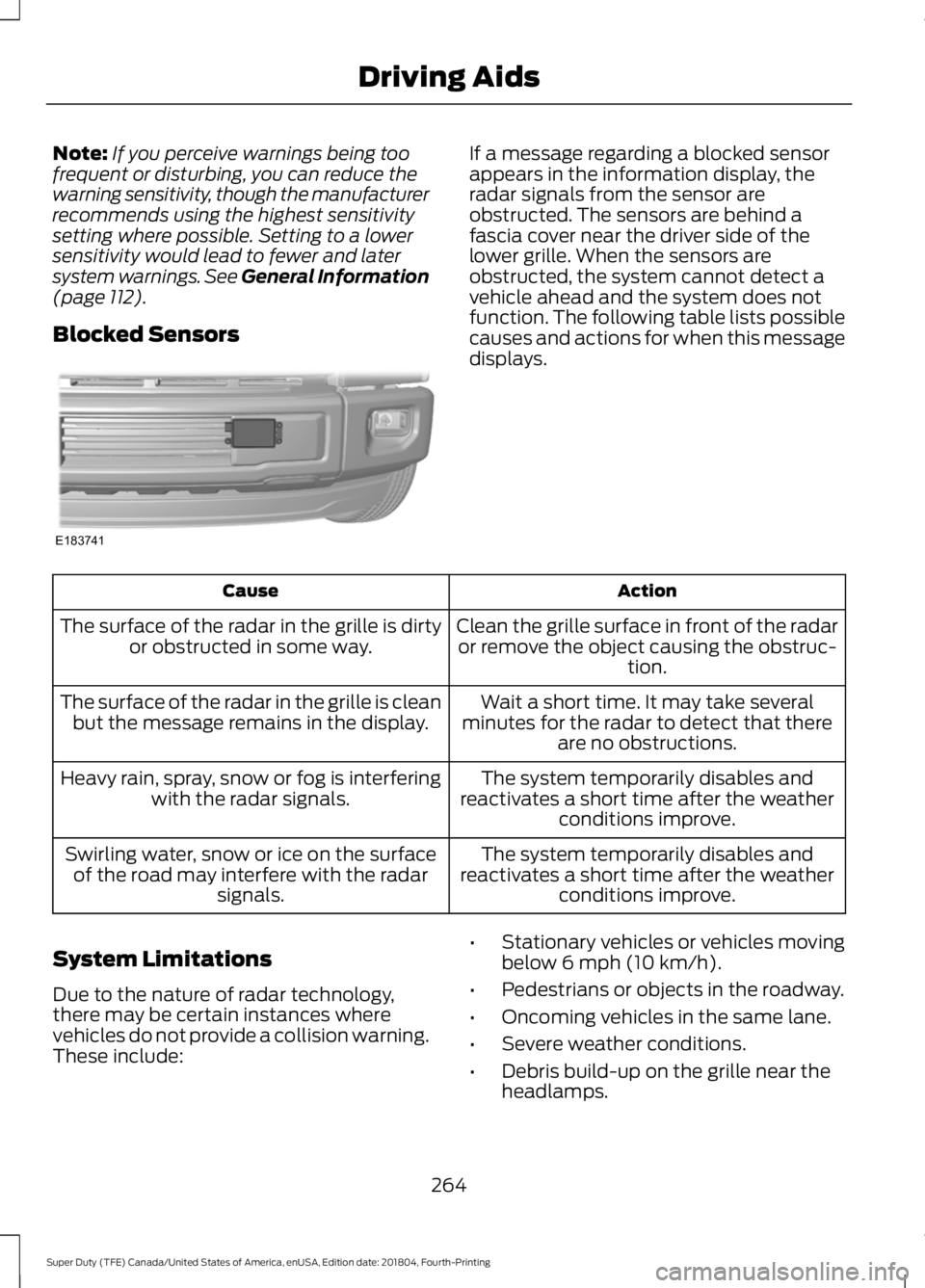
Blocked Sensors If a message regarding a blocked sensor
appears in the information display, the
radar signals from the sensor are
obstructed. The sensors are behind a
fascia cover near the driver side of the
lower grille. When the sensors are
obstructed, the system cannot detect a
vehicle ahead and the system does not
function. The following table lists possible
causes and actions for when this message
displays.
Action
Cause
Clean the grille surface in front of the radaror remove the object causing the obstruc- tion.
The surface of the radar in the grille is dirty
or obstructed in some way.
Wait a short time. It may take several
minutes for the radar to detect that there are no obstructions.
The surface of the radar in the grille is clean
but the message remains in the display.
The system temporarily disables and
reactivates a short time after the weather conditions improve.
Heavy rain, spray, snow or fog is interfering
with the radar signals.
The system temporarily disables and
reactivates a short time after the weather conditions improve.
Swirling water, snow or ice on the surface
of the road may interfere with the radar signals.
System Limitations
Due to the nature of radar technology,
there may be certain instances where
vehicles do not provide a collision warning.
These include: •
Stationary vehicles or vehicles moving
below
6 mph (10 km/h).
• Pedestrians or objects in the roadway.
• Oncoming vehicles in the same lane.
• Severe weather conditions.
• Debris build-up on the grille near the
headlamps.
264
Super Duty (TFE) Canada/United States of America, enUSA, Edition date: 201804, Fourth-Printing Driving AidsE183741
Page 275 of 666
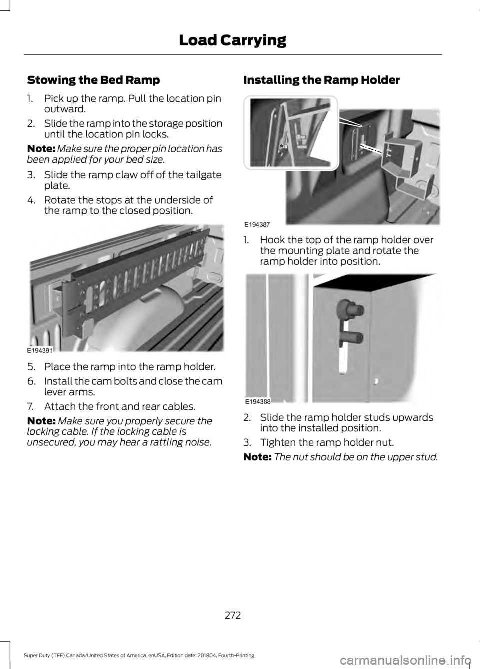
Stowing the Bed Ramp
1. Pick up the ramp. Pull the location pin
outward.
2. Slide the ramp into the storage position
until the location pin locks.
Note: Make sure the proper pin location has
been applied for your bed size.
3. Slide the ramp claw off of the tailgate plate.
4. Rotate the stops at the underside of the ramp to the closed position. 5. Place the ramp into the ramp holder.
6.
Install the cam bolts and close the cam
lever arms.
7. Attach the front and rear cables.
Note: Make sure you properly secure the
locking cable. If the locking cable is
unsecured, you may hear a rattling noise. Installing the Ramp Holder 1. Hook the top of the ramp holder over
the mounting plate and rotate the
ramp holder into position. 2. Slide the ramp holder studs upwards
into the installed position.
3. Tighten the ramp holder nut.
Note: The nut should be on the upper stud.
272
Super Duty (TFE) Canada/United States of America, enUSA, Edition date: 201804, Fourth-Printing Load CarryingE194391 E194387 E194388
Page 284 of 666
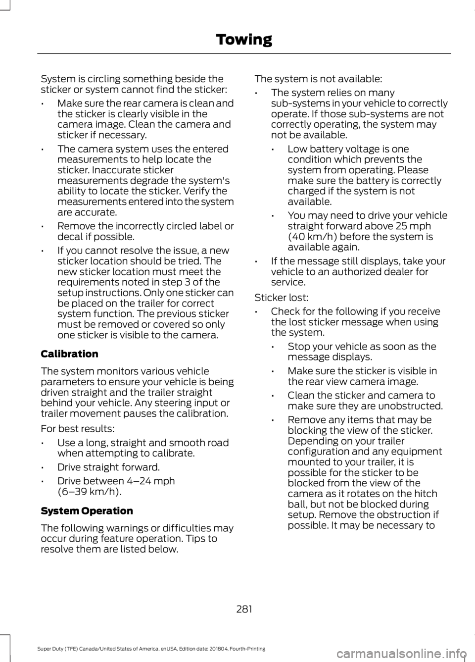
System is circling something beside the
sticker or system cannot find the sticker:
•
Make sure the rear camera is clean and
the sticker is clearly visible in the
camera image. Clean the camera and
sticker if necessary.
• The camera system uses the entered
measurements to help locate the
sticker. Inaccurate sticker
measurements degrade the system's
ability to locate the sticker. Verify the
measurements entered into the system
are accurate.
• Remove the incorrectly circled label or
decal if possible.
• If you cannot resolve the issue, a new
sticker location should be tried. The
new sticker location must meet the
requirements noted in step 3 of the
setup instructions. Only one sticker can
be placed on the trailer for correct
system function. The previous sticker
must be removed or covered so only
one sticker is visible to the camera.
Calibration
The system monitors various vehicle
parameters to ensure your vehicle is being
driven straight and the trailer straight
behind your vehicle. Any steering input or
trailer movement pauses the calibration.
For best results:
• Use a long, straight and smooth road
when attempting to calibrate.
• Drive straight forward.
• Drive between 4–24 mph
(6– 39 km/h).
System Operation
The following warnings or difficulties may
occur during feature operation. Tips to
resolve them are listed below. The system is not available:
•
The system relies on many
sub-systems in your vehicle to correctly
operate. If those sub-systems are not
correctly operating, the system may
not be available.
•Low battery voltage is one
condition which prevents the
system from operating. Please
make sure the battery is correctly
charged if the system is not
available.
• You may need to drive your vehicle
straight forward above
25 mph
(40 km/h) before the system is
available again.
• If the message still displays, take your
vehicle to an authorized dealer for
service.
Sticker lost:
• Check for the following if you receive
the lost sticker message when using
the system.
•Stop your vehicle as soon as the
message displays.
• Make sure the sticker is visible in
the rear view camera image.
• Clean the sticker and camera to
make sure they are unobstructed.
• Remove any items that may be
blocking the view of the sticker.
Depending on your trailer
configuration and any equipment
mounted to your trailer, it is
possible for the sticker to be
blocked from the view of the
camera as it rotates on the hitch
ball, but not be blocked during
setup. Remove the obstruction if
possible. It may be necessary to
281
Super Duty (TFE) Canada/United States of America, enUSA, Edition date: 201804, Fourth-Printing Towing
Page 289 of 666
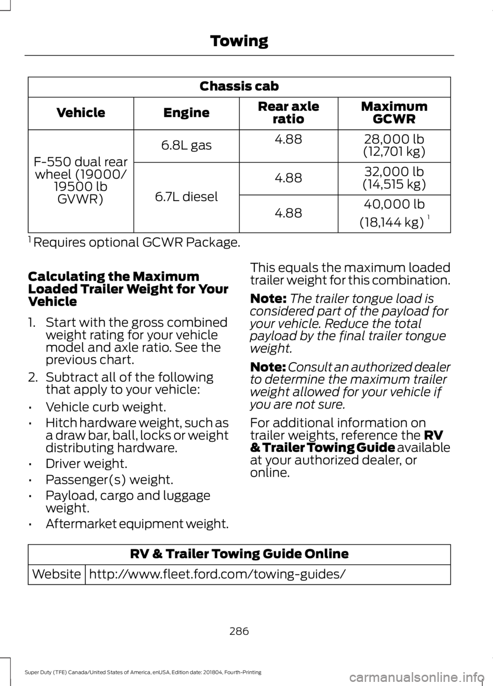
Chassis cab
MaximumGCWR
Rear axle
ratio
Engine
Vehicle
28,000 lb
(12,701 kg)
4.88
6.8L gas
F-550 dual rear wheel (19000/ 19500 lbGVWR) 32,000 lb
(14,515 kg)
4.88
6.7L diesel 40,000 lb
(18,144 kg) 1
4.88
1 Requires optional GCWR Package.
Calculating the Maximum
Loaded Trailer Weight for Your
Vehicle
1. Start with the gross combined weight rating for your vehicle
model and axle ratio. See the
previous chart.
2. Subtract all of the following
that apply to your vehicle:
• Vehicle curb weight.
• Hitch hardware weight, such as
a draw bar, ball, locks or weight
distributing hardware.
• Driver weight.
• Passenger(s) weight.
• Payload, cargo and luggage
weight.
• Aftermarket equipment weight. This equals the maximum loaded
trailer weight for this combination.
Note:
The trailer tongue load is
considered part of the payload for
your vehicle. Reduce the total
payload by the final trailer tongue
weight.
Note: Consult an authorized dealer
to determine the maximum trailer
weight allowed for your vehicle if
you are not sure.
For additional information on
trailer weights, reference the RV
& Trailer Towing Guide available
at your authorized dealer, or
online. RV & Trailer Towing Guide Online
http://www.fleet.ford.com/towing-guides/
Website
286
Super Duty (TFE) Canada/United States of America, enUSA, Edition date: 201804, Fourth-Printing Towing
Page 293 of 666
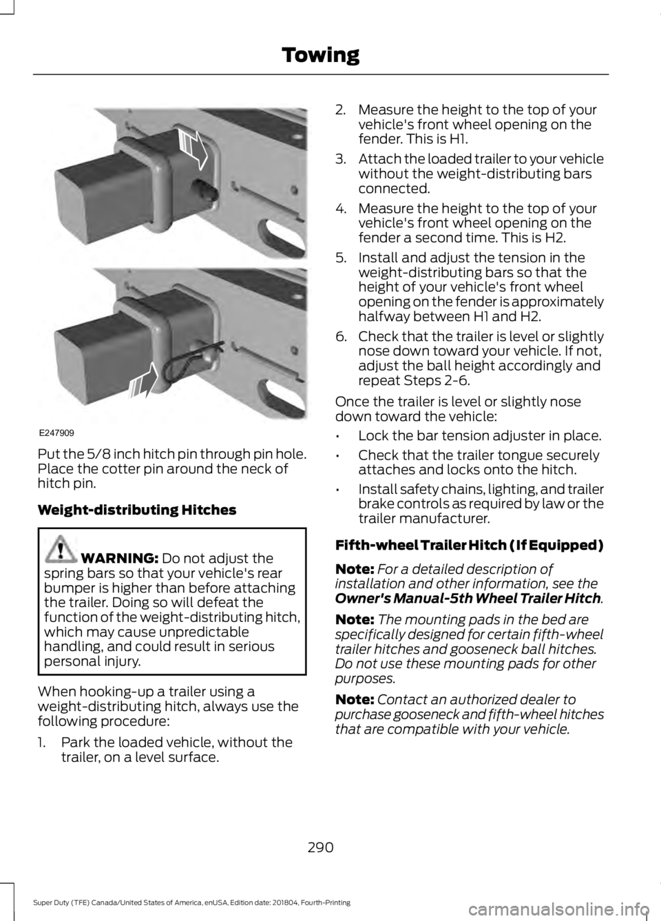
Put the 5/8 inch hitch pin through pin hole.
Place the cotter pin around the neck of
hitch pin.
Weight-distributing Hitches
WARNING: Do not adjust the
spring bars so that your vehicle's rear
bumper is higher than before attaching
the trailer. Doing so will defeat the
function of the weight-distributing hitch,
which may cause unpredictable
handling, and could result in serious
personal injury.
When hooking-up a trailer using a
weight-distributing hitch, always use the
following procedure:
1. Park the loaded vehicle, without the trailer, on a level surface. 2. Measure the height to the top of your
vehicle's front wheel opening on the
fender. This is H1.
3. Attach the loaded trailer to your vehicle
without the weight-distributing bars
connected.
4. Measure the height to the top of your vehicle's front wheel opening on the
fender a second time. This is H2.
5. Install and adjust the tension in the weight-distributing bars so that the
height of your vehicle's front wheel
opening on the fender is approximately
halfway between H1 and H2.
6. Check that the trailer is level or slightly
nose down toward your vehicle. If not,
adjust the ball height accordingly and
repeat Steps 2-6.
Once the trailer is level or slightly nose
down toward the vehicle:
• Lock the bar tension adjuster in place.
• Check that the trailer tongue securely
attaches and locks onto the hitch.
• Install safety chains, lighting, and trailer
brake controls as required by law or the
trailer manufacturer.
Fifth-wheel Trailer Hitch (If Equipped)
Note: For a detailed description of
installation and other information, see the
Owner's Manual-5th Wheel Trailer Hitch.
Note: The mounting pads in the bed are
specifically designed for certain fifth-wheel
trailer hitches and gooseneck ball hitches.
Do not use these mounting pads for other
purposes.
Note: Contact an authorized dealer to
purchase gooseneck and fifth-wheel hitches
that are compatible with your vehicle.
290
Super Duty (TFE) Canada/United States of America, enUSA, Edition date: 201804, Fourth-Printing TowingE247909
Page 295 of 666
Integrated Trailer Brake Controller
(If Equipped)
WARNING: The anti-lock brake
system does not control the trailer
brakes. WARNING:
Use the integrated
trailer brake controller to properly adjust
the trailer brakes and check all
connections before towing a trailer.
Failure to follow this instruction could
result in the loss of control of your
vehicle, personal injury or death.
Note: The integrated Ford brake controller
is compatible with trailers equipped with
electric-actuated drum brakes and
electric-over hydraulic brake systems.
Note: The integrated Ford brake controller
does not control hydraulic surge-style
brakes. When used properly, the trailer brake
controller assists in smooth and effective
trailer braking by powering the trailer
’s
electric or electric-over-hydraulic brakes
with a proportional output based on the
towing vehicle ’s brake pressure.
You can adjust the amount of initial trailer
brake output by selecting one of three
settings through the message center. Ford has tested the trailer brake controller
to be compatible with several major
brands of electric-over-hydraulic trailer
brakes. Contact an authorized dealer for
information on which brands you can use.
The controller user interface consists of
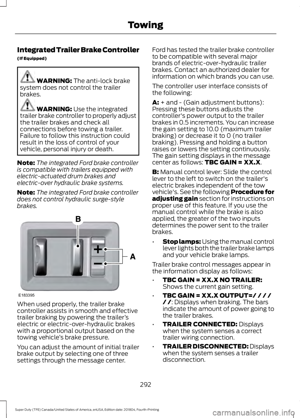
the following:
A: + and - (Gain adjustment buttons):
Pressing these buttons adjusts the
controller's power output to the trailer
brakes in 0.5 increments. You can increase
the gain setting to 10.0 (maximum trailer
braking) or decrease it to 0 (no trailer
braking). Pressing and holding a button
raises or lowers the setting continuously.
The gain setting displays in the message
center as follows:
TBC GAIN = XX.X.
B:
Manual control lever: Slide the control
lever to the left to switch on the trailer's
electric brakes independent of the tow
vehicle's. See the following Procedure for
adjusting gain section for instructions on
proper use of this feature. If you use the
manual control while the brake is also
applied, the greater of the two inputs
determines the power sent to the trailer
brakes.
• Stop lamps: Using the manual control
lever lights both the trailer brake lamps
and your vehicle brake lamps.
Trailer brake control messages appear in
the information display as follows:
• TBC GAIN = XX.X NO TRAILER:
Shows the current gain setting.
• TBC GAIN = XX.X OUTPUT=/ / / /
/ /
: Displays when braking. The bars
indicate the amount of power going to
the trailer brakes.
• TRAILER CONNECTED:
Displays
when the system senses a correct
trailer wiring connection.
• TRAILER DISCONNECTED: Displays
when the system senses a trailer
disconnection.
292
Super Duty (TFE) Canada/United States of America, enUSA, Edition date: 201804, Fourth-Printing TowingE183395
Page 296 of 666
Procedure for Setting Trailer Brake
Controller Effort
Choose either the electric option for trailers
with electromagnetic drum brakes, or the
electric over hydraulic option for trailers
with these brake systems.
Trailer Brake Effort Setting
The trailer brake controller allows the user
to customize how aggressively the trailer
brakes engage. The default value is the low
setting and is the recommended setting
for most trailers. If your trailer's brakes
require more initial voltage, or if you prefer
more aggressive trailer braking, then select
either the medium or the high setting.
Procedure for Setting Trailer Brake
Controller Mode
Choose the low, medium or high setting
for the required initial trailer brake output.
Procedure for Adjusting Gain
Note:
Only perform this procedure in a
traffic-free environment at speeds of
approximately 20– 25 mph (30–40 km/h).
The gain setting adjusts the trailer brake
controller for the specific towing condition.
You should change the setting as towing
conditions change. Changes to towing
conditions include trailer load, vehicle load,
road conditions and weather.
The gain should be set to provide the
maximum trailer braking assistance while
making sure the trailer wheels do not lock
when using the brakes. Locked trailer
wheels may lead to trailer instability.
1. Make sure the trailer brakes are in good
working condition, functioning normally
and properly adjusted. See your trailer
dealer if necessary.
2. Hook up the trailer and make the electrical connections according to the
trailer manufacturer's instructions. 3. When you plug in a trailer with electric
or electric-over-hydraulic brakes, a
confirmation message appears in the
information display.
4. Use the gain adjustment (+ and -) buttons to increase or decrease the
gain setting to the desired starting
point. A gain setting of 6.0 is a good
starting point for heavier loads.
5. In a traffic-free environment, tow the trailer on a dry, level surface at a speed
of
20– 25 mph (30–40 km/h) and
squeeze the manual control lever
completely.
6. If the trailer wheels lock up, indicated by squealing tires, reduce the gain
setting. If the trailer wheels turn freely,
increase the gain setting. Repeat Steps
5 and 6 until the gain setting is at a
point just below trailer wheel lock-up.
If towing a heavier trailer, trailer wheel
lock-up may not be attainable even
with the maximum gain setting of 10.
Information Display Warning Messages
Note: An authorized dealer can diagnose
the trailer brake controller to determine
exactly which trailer fault has occurred.
However, your Ford warranty does not cover
this diagnosis if the fault is with the trailer.
TRAILER BRAKE MODULE FAULT
Displays in response to faults sensed by
the trailer brake controller, accompanied
by a single tone. If this message appears,
contact an authorized dealer as soon as
possible for diagnosis and repair. The
controller may still function, but with
degraded performance.
WIRING FAULT ON TRAILER
Displays when there is a short circuit on
the electric brake output wire.
293
Super Duty (TFE) Canada/United States of America, enUSA, Edition date: 201804, Fourth-Printing Towing
Page 297 of 666
If this message displays, with no trailer
connected, the problem is with your vehicle
wiring or trailer brake controller. Contact
an authorized dealer.
If the message only displays with a trailer
connected, the problem is with the trailer
wiring. Consult your trailer dealer for
assistance. This can be a short to ground
(such as a chaffed wire), short to voltage
(such as a pulled pin on trailer emergency
breakaway battery) or the trailer brakes
may be drawing too much current.
Points to Remember
Note:
Do not attempt removal of the trailer
brake controller without consulting the
Workshop Manual. Damage to the unit may
result.
• Adjust gain setting before using the
trailer brake controller.
• Adjust gain setting, using the procedure
above, whenever road, weather, trailer
or vehicle loading conditions change
from when the gain was initially set.
• Only use the manual control lever for
proper adjustment of the gain during
trailer setup. Misuse, such as
application during trailer sway, could
cause instability of trailer or tow
vehicle.
• Avoid towing in adverse weather
conditions. The trailer brake controller
does not provide anti-lock control of
the trailer wheels. Trailer wheels can
lock up on slippery surfaces, resulting
in reduced stability of trailer and tow
vehicle.
• The trailer brake controller is equipped
with a feature that reduces output at
vehicle speeds below 11 mph (18 km/h)
so trailer and vehicle braking is not jerky
or harsh. This feature is only active
when applying the brakes using your
vehicle's brake pedal, not the
controller. •
The controller interacts with the brake
control system and powertrain control
system of your vehicle to provide the
best performance on different road
conditions.
• Your vehicle's brake system and the
trailer brake system work
independently of each other. Changing
the gain setting on the controller does
not affect the operation of your
vehicle's brakes.
• When you switch the engine off, the
controller output is disabled and the
display and module shut down.
Trailer Lamps WARNING: Never connect any
trailer lamp wiring to the vehicle's tail
lamp wiring; this may damage the
electrical system resulting in fire. Contact
your authorized dealer as soon as
possible for assistance in proper trailer
tow wiring installation. Additional
electrical equipment may be required.
Trailer lamps are required on most towed
vehicles. Make sure all running lights, brake
lights, turn signals and hazard lights are
working.
Before Towing a Trailer
Practice turning, stopping and backing up
to get the feel of your vehicle-trailer
combination before starting on a trip.
When turning, make wider turns so the
trailer wheels clear curbs and other
obstacles.
294
Super Duty (TFE) Canada/United States of America, enUSA, Edition date: 201804, Fourth-Printing Towing