instrument cluster FORD F-250 2019 Owner's Manual
[x] Cancel search | Manufacturer: FORD, Model Year: 2019, Model line: F-250, Model: FORD F-250 2019Pages: 666, PDF Size: 13.6 MB
Page 244 of 666
PRINCIPLE OF OPERATION
Cruise control lets you maintain a set
speed without keeping your foot on the
accelerator pedal. You can use cruise
control when your vehicle speed is greater
than 20 mph (30 km/h).
USING CRUISE CONTROL WARNING:
Do not use cruise
control on winding roads, in heavy traffic
or when the road surface is slippery. This
could result in loss of vehicle control,
serious injury or death. WARNING:
When you are going
downhill, your vehicle speed could
increase above the set speed. The
system does not apply the brakes.
To help the system to maintain the set
speed when going downhill, downshift to
a lower gear.
Your vehicle speed could decrease below
the set speed when driving uphill.
Note: The system cancels if your vehicle
speed drops below 10 mph (16 km/h) under
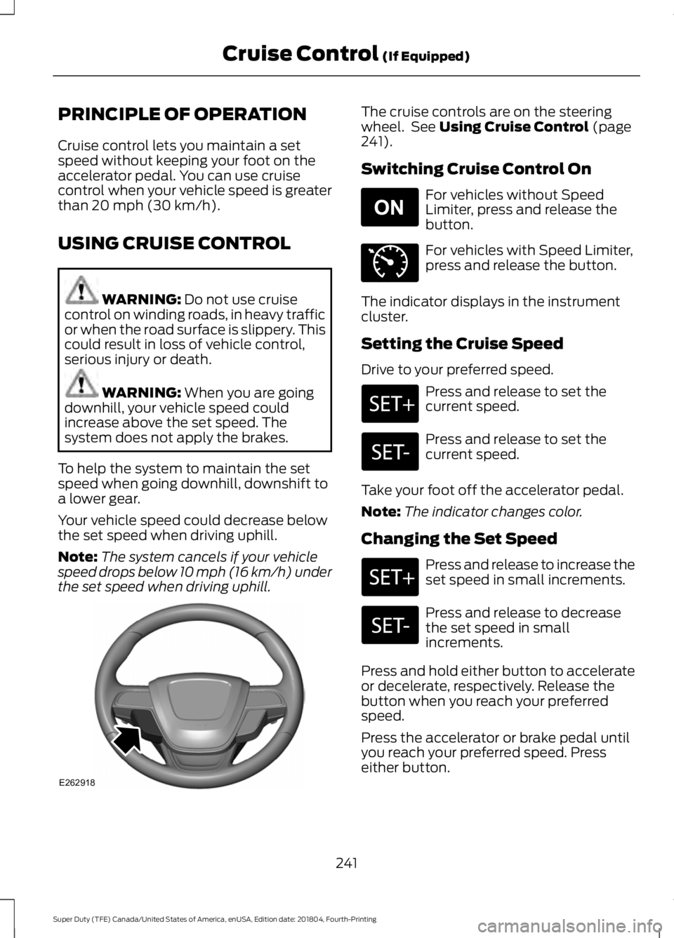
the set speed when driving uphill. The cruise controls are on the steering
wheel. See
Using Cruise Control (page
241).
Switching Cruise Control On For vehicles without Speed
Limiter, press and release the
button.
For vehicles with Speed Limiter,
press and release the button.
The indicator displays in the instrument
cluster.
Setting the Cruise Speed
Drive to your preferred speed. Press and release to set the
current speed.
Press and release to set the
current speed.
Take your foot off the accelerator pedal.
Note: The indicator changes color.
Changing the Set Speed Press and release to increase the
set speed in small increments.
Press and release to decrease
the set speed in small
increments.
Press and hold either button to accelerate
or decelerate, respectively. Release the
button when you reach your preferred
speed.
Press the accelerator or brake pedal until
you reach your preferred speed. Press
either button.
241
Super Duty (TFE) Canada/United States of America, enUSA, Edition date: 201804, Fourth-Printing Cruise Control
(If Equipped)E262918 E265296 E71340
Page 247 of 666
WARNING: The system only warns
of vehicles detected by the radar sensor.
In some cases there may be no warning
or a delayed warning. Apply the brakes
when necessary. Failure to follow this
instruction could result in personal injury
or death.
Note: When you are following a vehicle and
you switch on a direction indicator, adaptive
cruise control may provide a small
temporary acceleration to help you pass.
Note: The brakes may emit noise when
applied by the system.
When a vehicle ahead of you enters the
same lane or a slower vehicle is ahead in
the same lane, the vehicle speed adjusts
to maintain a preset gap distance. A
vehicle graphic illuminates in the
instrument cluster.
Your vehicle maintains a consistent gap
from the vehicle ahead until:
• The vehicle in front of you accelerates
to a speed above the set speed.
• The vehicle in front of you moves out
of the lane you are in.
• Your vehicle speed falls below 12 mph
(20 km/h).
• You set a new gap distance.
The system applies the brakes to slow your
vehicle to maintain a safe gap distance
from the vehicle in front. The system only
applies limited braking. You can override
the system by applying the brakes.
If the system determines that its maximum
braking level is not sufficient, an audible
warning sounds, a message appears in the
information display and an indicator
flashes when the system continues to
brake. Take immediate action. Setting the Gap Distance
You can decrease or increase the distance
between your vehicle and the vehicle in
front by pressing the gap control. Press and release to decrease
the gap distance.
Press and release to increase the
gap distance.
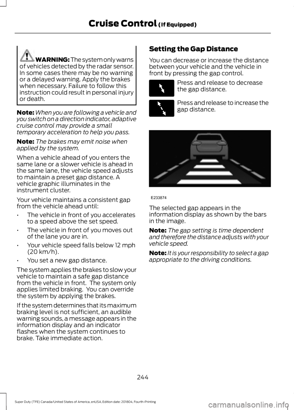
The selected gap appears in the
information display as shown by the bars
in the image.
Note:
The gap setting is time dependent
and therefore the distance adjusts with your
vehicle speed.
Note: It is your responsibility to select a gap
appropriate to the driving conditions.
244
Super Duty (TFE) Canada/United States of America, enUSA, Edition date: 201804, Fourth-Printing Cruise Control
(If Equipped)E263697 E263696 E233874
Page 258 of 666
The system uses radar sensors that are
located inside the tail lamp on each side
of your vehicle. Any dirt, mud and snow in
front of the sensors or driving in heavy rain
can cause system degradation. Also, other
types of obstructions in front of the sensor
can cause system degradation. This is
referred to as a
‘blocked ’ condition.
Note: Do not apply bumper stickers and/or
repair compound to these areas, this can
cause degraded system performance.
If the system detects a degraded
performance condition, a message warning
appears in the display screen. The alert
indicators remain ON and the system no
longer provides any warnings. You can
clear the warning but the alert indicators
remain illuminated.
A "blocked" condition can be cleared in
two ways:
• After the blockage in front of the
sensors is removed or the
rainfall/snowfall rate decreases or
stops, drive for a few minutes in traffic
to allow the sensors to detect passing
vehicles.
• By cycling the ignition from ON to OFF
and then back ON.
Note: If your vehicle has a tow bar with a
factory equipped trailer tow module and it
is towing a trailer, the sensors will
automatically turn the Blind Spot
Information System off. If your vehicle has
a tow bar but no factory equipped trailer
tow module, it is recommended to turn the
Blind Spot Information System off
manually. Operating the Blind Spot
Information System without the Blind Spot
Trailer Tow package and a trailer attached
will cause poor system performance. Blind Spot Information System
with Trailer Tow (If Equipped)
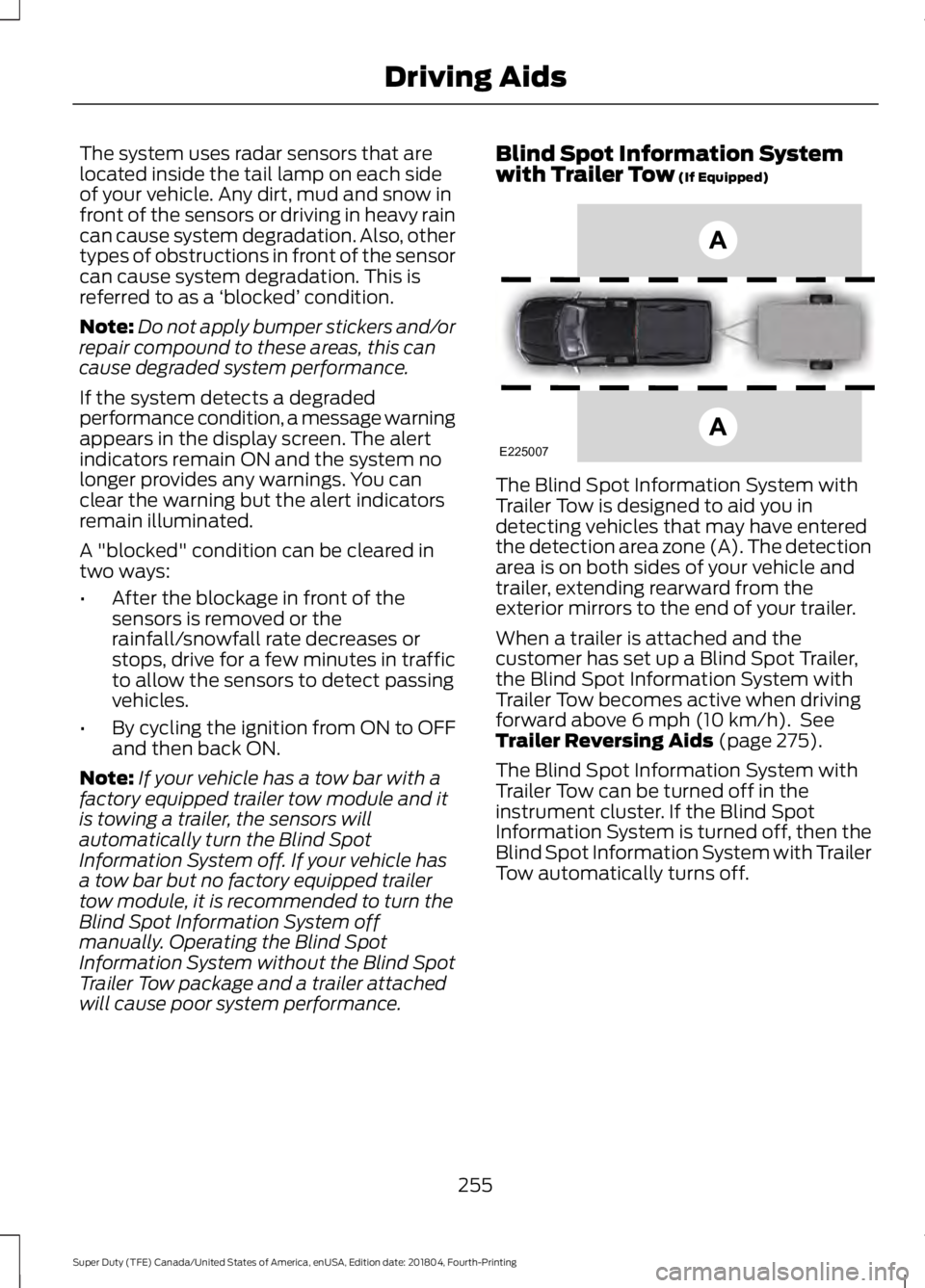
The Blind Spot Information System with
Trailer Tow is designed to aid you in
detecting vehicles that may have entered
the detection area zone (A). The detection
area is on both sides of your vehicle and
trailer, extending rearward from the
exterior mirrors to the end of your trailer.
When a trailer is attached and the
customer has set up a Blind Spot Trailer,
the Blind Spot Information System with
Trailer Tow becomes active when driving
forward above
6 mph (10 km/h). See
Trailer Reversing Aids (page 275).
The Blind Spot Information System with
Trailer Tow can be turned off in the
instrument cluster. If the Blind Spot
Information System is turned off, then the
Blind Spot Information System with Trailer
Tow automatically turns off.
255
Super Duty (TFE) Canada/United States of America, enUSA, Edition date: 201804, Fourth-Printing Driving AidsE225007
Page 259 of 666
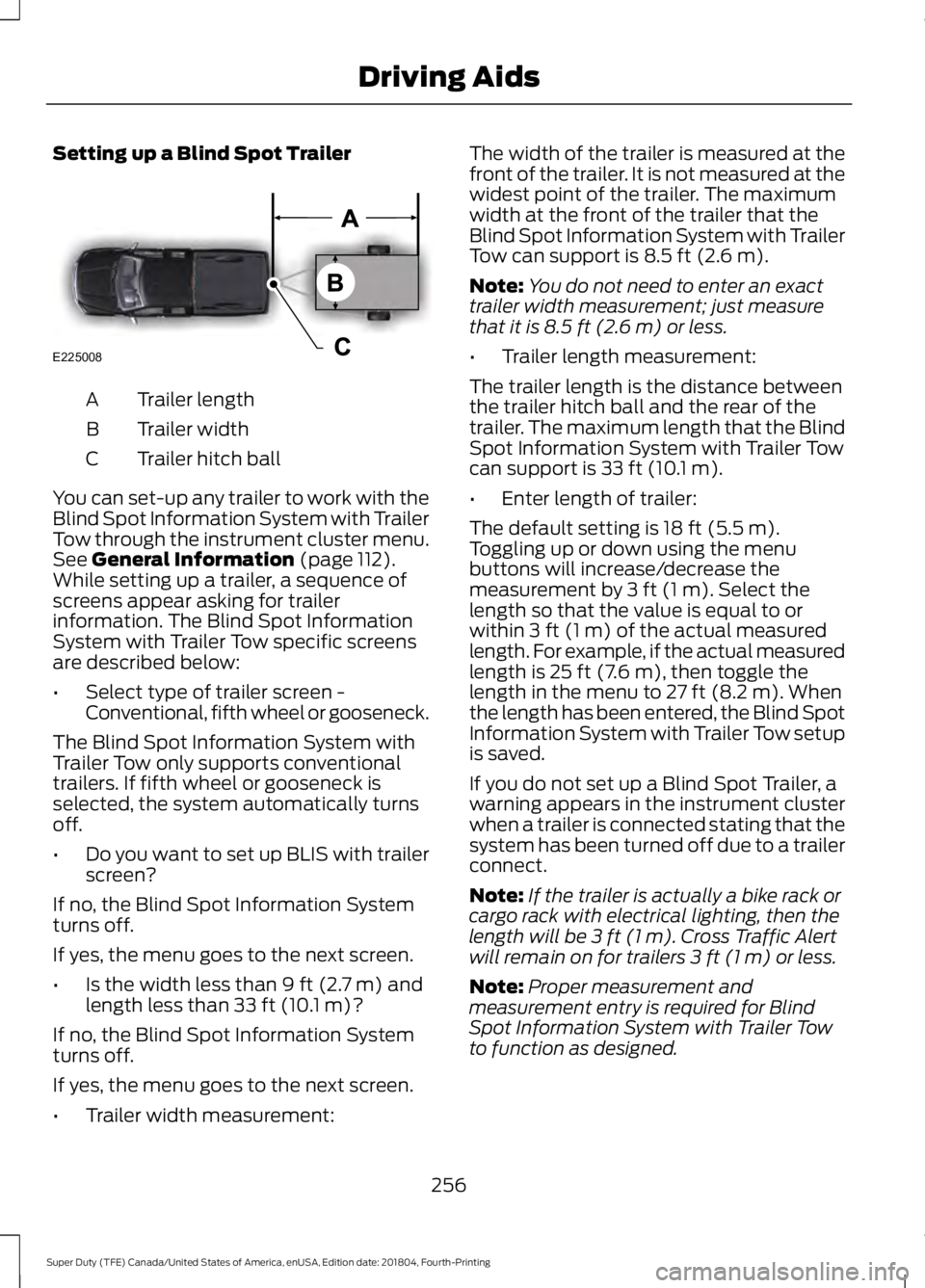
Setting up a Blind Spot Trailer
Trailer length
A
Trailer width
B
Trailer hitch ball
C
You can set-up any trailer to work with the
Blind Spot Information System with Trailer
Tow through the instrument cluster menu.
See General Information (page 112).
While setting up a trailer, a sequence of
screens appear asking for trailer
information. The Blind Spot Information
System with Trailer Tow specific screens
are described below:
• Select type of trailer screen -
Conventional, fifth wheel or gooseneck.
The Blind Spot Information System with
Trailer Tow only supports conventional
trailers. If fifth wheel or gooseneck is
selected, the system automatically turns
off.
• Do you want to set up BLIS with trailer
screen?
If no, the Blind Spot Information System
turns off.
If yes, the menu goes to the next screen.
• Is the width less than
9 ft (2.7 m) and
length less than 33 ft (10.1 m)?
If no, the Blind Spot Information System
turns off.
If yes, the menu goes to the next screen.
• Trailer width measurement: The width of the trailer is measured at the
front of the trailer. It is not measured at the
widest point of the trailer. The maximum
width at the front of the trailer that the
Blind Spot Information System with Trailer
Tow can support is
8.5 ft (2.6 m).
Note: You do not need to enter an exact
trailer width measurement; just measure
that it is
8.5 ft (2.6 m) or less.
• Trailer length measurement:
The trailer length is the distance between
the trailer hitch ball and the rear of the
trailer. The maximum length that the Blind
Spot Information System with Trailer Tow
can support is
33 ft (10.1 m).
• Enter length of trailer:
The default setting is
18 ft (5.5 m).
Toggling up or down using the menu
buttons will increase/decrease the
measurement by
3 ft (1 m). Select the
length so that the value is equal to or
within
3 ft (1 m) of the actual measured
length. For example, if the actual measured
length is
25 ft (7.6 m), then toggle the
length in the menu to 27 ft (8.2 m). When
the length has been entered, the Blind Spot
Information System with Trailer Tow setup
is saved.
If you do not set up a Blind Spot Trailer, a
warning appears in the instrument cluster
when a trailer is connected stating that the
system has been turned off due to a trailer
connect.
Note: If the trailer is actually a bike rack or
cargo rack with electrical lighting, then the
length will be
3 ft (1 m). Cross Traffic Alert
will remain on for trailers 3 ft (1 m) or less.
Note: Proper measurement and
measurement entry is required for Blind
Spot Information System with Trailer Tow
to function as designed.
256
Super Duty (TFE) Canada/United States of America, enUSA, Edition date: 201804, Fourth-Printing Driving AidsE225008
Page 260 of 666
System Operation
If you select a trailer in the display screen
prior to connecting the trailer, the system
will load that configuration and the
information cluster displays a message
when the trailer is connected. A second
message appears stating Cross Traffic
Alert has been turned off; the Blind Spot
Information System with Trailer Tow still
functions normally when driving forward.
If no trailer has been set up and a trailer is
connected, the instrument cluster provides
a message indicating a trailer is connected
followed by a message asking to select a
trailer from the existing list of trailers or to
add a trailer. In order for the Blind Spot
Information System with Trailer Tow to
function, an existing trailer must be
selected or a new trailer must be added. If
the request is ignored or if you exit the
screen, a message appears prompting you
that the system has been turned off due
to a trailer connect. This message may not
appear until your vehicle speed reaches
22 mph (35 km/h).
The Blind Spot Information System with
Trailer Tow activates when driving forward
for that particular trailer set up. If the
ignition is cycled, the Blind Spot
Information System with Trailer Tow
continues to function using the last trailer
selected.
Trailer Considerations
The Blind Spot Information System with
Trailer Tow is designed to work with any
trailer whose front width is
8.5 ft (2.6 m)
or less and total length from the trailer
hitch ball to the rear of the trailer is
33 ft
(10.1 m) or less. Different trailers may
cause a slight change in performance as
outlined below. Large box trailers may cause false alerts
to trigger when driving next to buildings or
near parking cars. A false alert may also
occur while making a 90-degree turn.
Trailers that are
8.5 ft (2.6 m) wide at the
front and have a total length greater than
20 ft (6 m)
may have delayed alerts from
passing vehicles when the vehicle is
passing at high speed.
A box trailer whose front width is
8.5 ft
(2.6 m) may cause early alerts when you
are over taking a vehicle.
When towing a clam shell or V-Nose box
trailer with a front width of
8.5 ft (2.6 m),
delayed alerts on merging vehicles that are
traveling the same speed as your vehicle
may occur.
System Errors
If the system senses a problem with the
left or right sensor, the telltale illuminates
and a message appears in the display
screen. See
Information Messages
(page 128).
Switching the System Off and On
You can temporarily switch the Blind Spot
Information System off in the display
screen. See
General Information (page
112). When the Blind Spot Information
System switches off, you do not receive
alerts and the display screen shows a
system off message. The telltale in the
cluster also illuminates. When you switch
the Blind Spot Information System on or
off, the alert indicators flash twice.
Note: The Blind Spot Information System
remembers the last selected on or off
setting.
You can also have the Blind Spot
Information System switched off
permanently at an authorized dealer. Once
switched off permanently, the system can
only be switched back on at an authorized
dealer.
257
Super Duty (TFE) Canada/United States of America, enUSA, Edition date: 201804, Fourth-Printing Driving Aids
Page 301 of 666
Note:
You can check four-wheel-down
towing status at any time by opening the
driver's door or turning the ignition to the
accessory or on position and verifying a
message displays in the cluster.
To exit four-wheel-down towing and return
the transfer case to its 2H position:
1. With your vehicle still properly secured
to the tow vehicle, put the ignition in
the on position, but do not start the
engine. If your vehicle has an ignition
key, switch the key to on. If your vehicle
has intelligent access, press the engine
START/STOP
button once without
pressing the brake pedal.
2. Press and hold the brake pedal.
3. Shift the transmission out of neutral (N) and into any other gear.
4. Release the brake pedal.
Note: If completed successfully, the
2H
indicator light illuminates and a
confirmation message displays in the
instrument cluster.
Note: If the indicator light and message do
not display, you must perform the procedure
again from the beginning.
Note: You may hear an audible noise as the
transfer case shifts out of its neutral
position. This is normal.
Note: If a message displays in the
instrument cluster stating there is a shift
delay, transfer case gear tooth blockage
may be present. See
Resolving the Shift
Delay Issue after this section.
5. Apply the parking brake and disconnect
the vehicle from the tow vehicle.
6. Release the parking brake, start the engine and shift the transmission to
drive (D) to make sure the transfer
case is out of neutral (N). 7. If the transfer case does not
successfully shift out of neutral (N),
set the parking brake until you can have
your vehicle serviced.
Resolving the Shift Delay Issue
If the instrument cluster displays a shift
delay message, See
Information
Messages (page 128). You need to
perform the following steps:
1. Press and hold the brake pedal.
2. Put the transmission into neutral (N), and then start the engine.
3. With the engine running, shift the transmission to drive (D) and let the
vehicle roll forward, up to
3 ft (1 m).
You may hear an audible noise as the
transfer case shifts out of its neutral
position. This is normal.
4. When the issue is resolved, the instrument cluster displays a message
stating neutral tow is disabled.
298
Super Duty (TFE) Canada/United States of America, enUSA, Edition date: 201804, Fourth-Printing Towing
Page 328 of 666
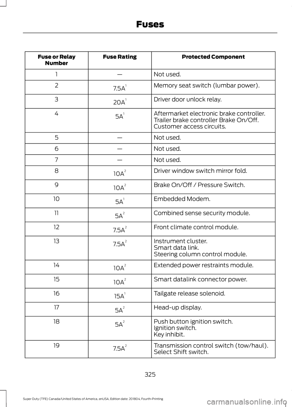
Protected Component
Fuse Rating
Fuse or Relay
Number
Not used.
—
1
Memory seat switch (lumbar power).
7.5A 1
2
Driver door unlock relay.
20A 1
3
Aftermarket electronic brake controller.
5A 1
4
Trailer brake controller Brake On/Off.
Customer access circuits.
Not used.
—
5
Not used.
—
6
Not used.
—
7
Driver window switch mirror fold.
10A 2
8
Brake On/Off / Pressure Switch.
10A 2
9
Embedded Modem.
5A 1
10
Combined sense security module.
5A 2
11
Front climate control module.
7.5A 2
12
Instrument cluster.
7.5A 2
13
Smart data link.
Steering column control module.
Extended power restraints module.
10A 2
14
Smart datalink connector power.
10A 2
15
Tailgate release solenoid.
15A 1
16
Head-up display.
5A 2
17
Push button ignition switch.
5A 2
18
Ignition switch.
Key inhibit.
Transmission control switch (tow/haul).
7.5A 2
19
Select Shift switch.
325
Super Duty (TFE) Canada/United States of America, enUSA, Edition date: 201804, Fourth-Printing Fuses
Page 342 of 666
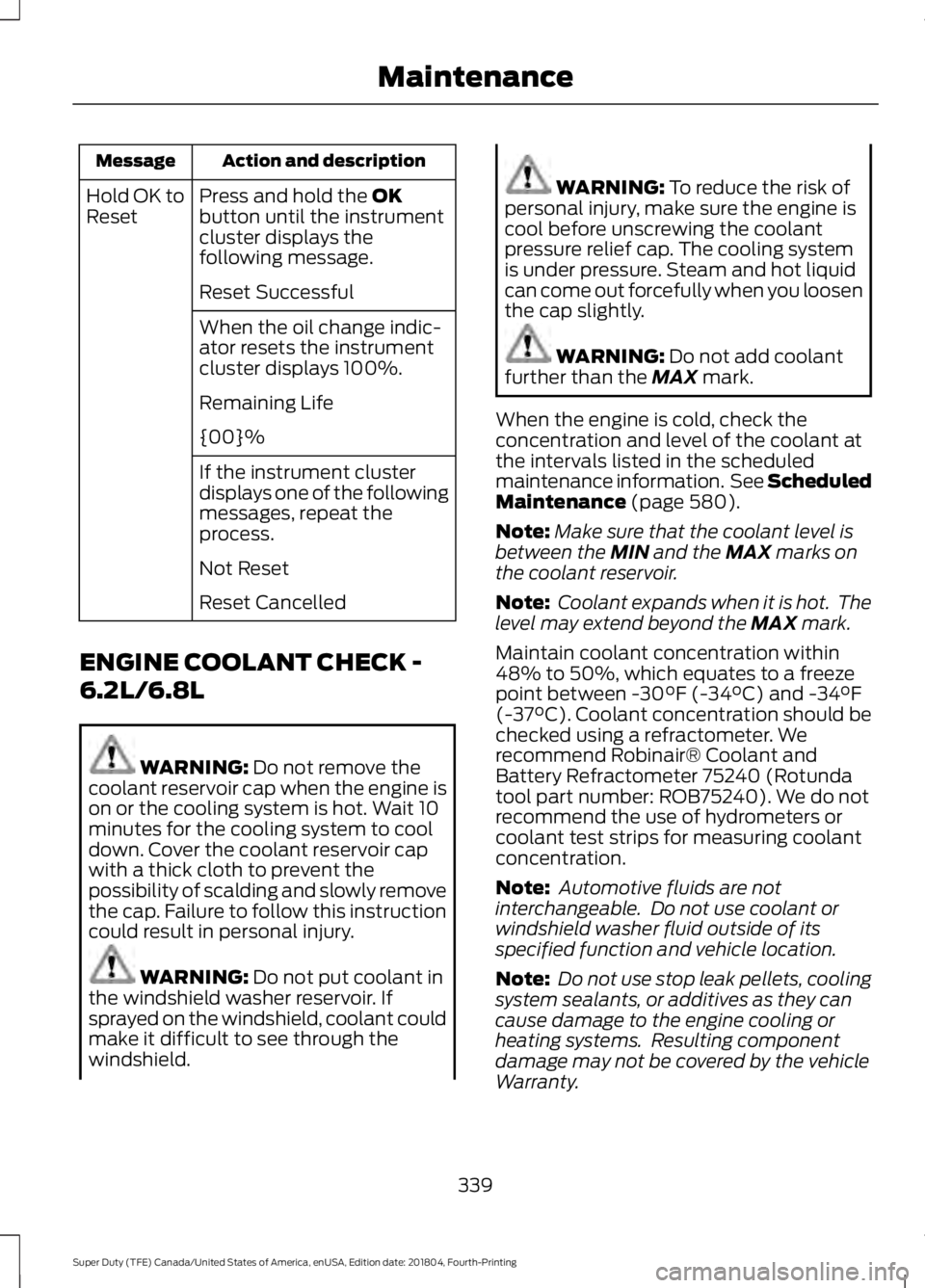
Action and description
Message
Press and hold the OK
button until the instrument
cluster displays the
following message.
Hold OK to
Reset
Reset Successful
When the oil change indic-
ator resets the instrument
cluster displays 100%.
Remaining Life
{00}%
If the instrument cluster
displays one of the following
messages, repeat the
process.
Not Reset
Reset Cancelled
ENGINE COOLANT CHECK -
6.2L/6.8L WARNING:
Do not remove the
coolant reservoir cap when the engine is
on or the cooling system is hot. Wait 10
minutes for the cooling system to cool
down. Cover the coolant reservoir cap
with a thick cloth to prevent the
possibility of scalding and slowly remove
the cap. Failure to follow this instruction
could result in personal injury. WARNING:
Do not put coolant in
the windshield washer reservoir. If
sprayed on the windshield, coolant could
make it difficult to see through the
windshield. WARNING:
To reduce the risk of
personal injury, make sure the engine is
cool before unscrewing the coolant
pressure relief cap. The cooling system
is under pressure. Steam and hot liquid
can come out forcefully when you loosen
the cap slightly. WARNING:
Do not add coolant
further than the MAX mark.
When the engine is cold, check the
concentration and level of the coolant at
the intervals listed in the scheduled
maintenance information. See Scheduled
Maintenance
(page 580).
Note: Make sure that the coolant level is
between the
MIN and the MAX marks on
the coolant reservoir.
Note: Coolant expands when it is hot. The
level may extend beyond the
MAX mark.
Maintain coolant concentration within
48% to 50%, which equates to a freeze
point between -30°F (-34°C) and -34°F
(-37°C). Coolant concentration should be
checked using a refractometer. We
recommend Robinair® Coolant and
Battery Refractometer 75240 (Rotunda
tool part number: ROB75240). We do not
recommend the use of hydrometers or
coolant test strips for measuring coolant
concentration.
Note: Automotive fluids are not
interchangeable. Do not use coolant or
windshield washer fluid outside of its
specified function and vehicle location.
Note: Do not use stop leak pellets, cooling
system sealants, or additives as they can
cause damage to the engine cooling or
heating systems. Resulting component
damage may not be covered by the vehicle
Warranty.
339
Super Duty (TFE) Canada/United States of America, enUSA, Edition date: 201804, Fourth-Printing Maintenance
Page 350 of 666
Refer to your scheduled maintenance
information for scheduled intervals for fluid
checks and changes. Your transmission
does not consume fluid. However, if the
transmission slips, slowly shifts or if you
notice a sign of leaking fluid, contact an
authorized dealer.
Checking Automatic Transmission
Fluid (If Equipped)
For scheduled intervals of the fluid checks
and changes, See
Scheduled
Maintenance (page 580). Your
transmission does not consume fluid.
However, the fluid level should be checked
if the transmission is not working properly,
i.e., if the transmission slips or shifts slowly
or if you notice some sign of fluid leakage.
Automatic transmission fluid expands
when warmed. To obtain an accurate fluid
check, drive the vehicle until it is at normal
operating temperature (approximately
19 mi (30 km)
). Verify that the
transmission fluid temperature gauge,
located on the instrument cluster, is within
normal range.
1. Drive the vehicle
19 mi (30 km) until it
reaches normal operating temperature.
2. Park the vehicle on a level surface and
engage the parking brake.
3. With the engine running, parking brake
engaged and your foot on the brake
pedal, move the gearshift lever through
all of the gear ranges. Allow sufficient
time for each gear to engage.
4. Latch the gearshift lever in park (P) and
leave the engine running.
5. Remove the dipstick, wiping it clean with a clean, dry lint free rag. If
necessary, refer to the Under Hood
Overview in this chapter for the
location of the dipstick. 6.
Install the dipstick making sure it is fully
seated in the filler tube.
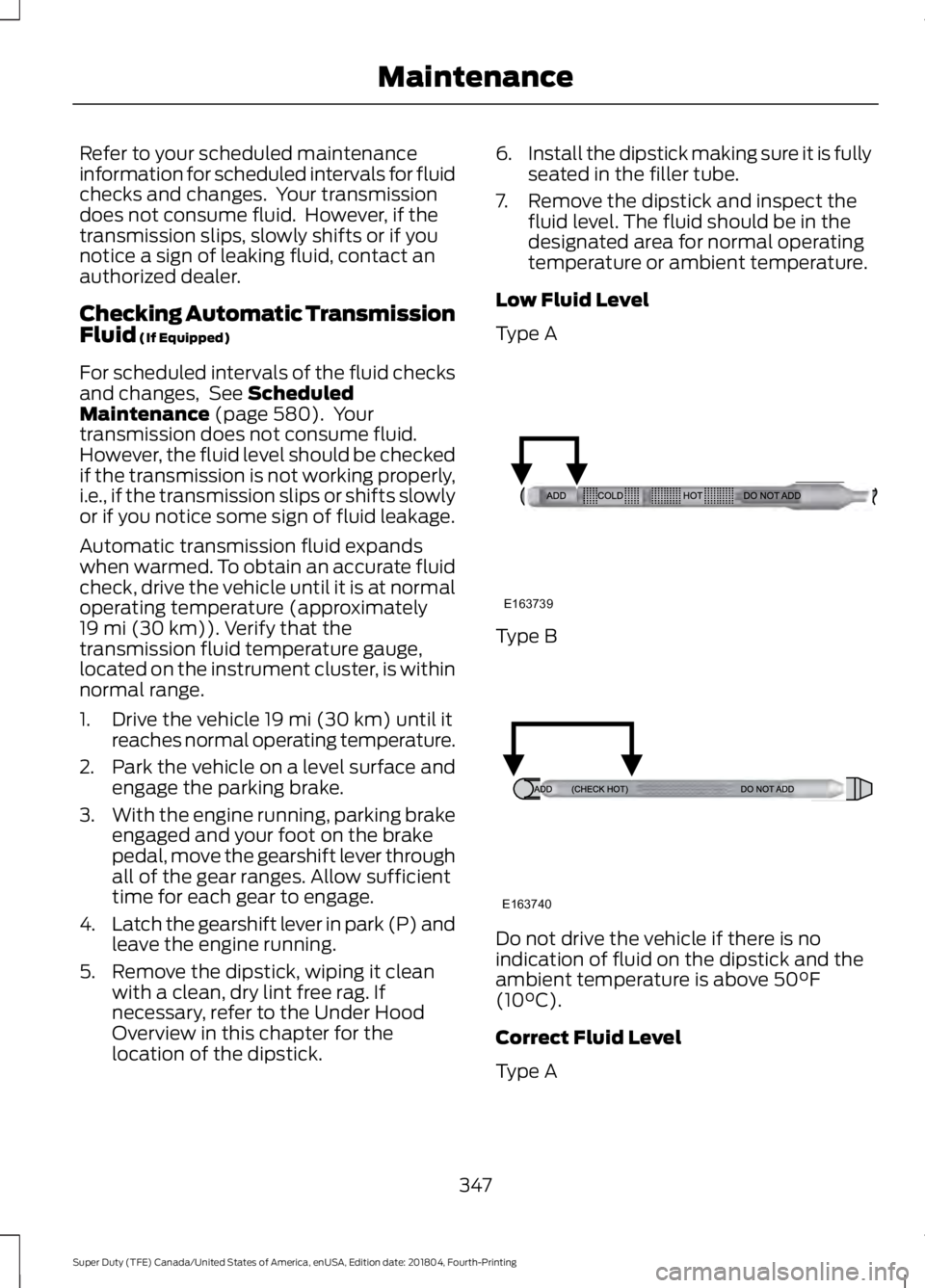
7. Remove the dipstick and inspect the fluid level. The fluid should be in the
designated area for normal operating
temperature or ambient temperature.
Low Fluid Level
Type A Type B
Do not drive the vehicle if there is no
indication of fluid on the dipstick and the
ambient temperature is above
50°F
(10°C).
Correct Fluid Level
Type A
347
Super Duty (TFE) Canada/United States of America, enUSA, Edition date: 201804, Fourth-Printing MaintenanceE163739 E163740
Page 377 of 666
CLEANING THE INSTRUMENT
PANEL AND INSTRUMENT
CLUSTER LENS
WARNING: Do not use chemical
solvents or strong detergents when
cleaning the steering wheel or
instrument panel to avoid contamination
of the airbag system.
Note: Follow the same procedure as
cleaning leather seats for cleaning leather
instrument panels and leather interior trim
surfaces. See
Cleaning Leather Seats
(page 374).
Clean the instrument panel and cluster
lens with a clean, damp and soft cloth,
then use a clean, dry and soft cloth to dry
these areas.
• Avoid cleaners or polishes that increase
the gloss of the upper portion of the
instrument panel. The dull finish in this
area helps protect you from
undesirable windshield reflection.
• Do not use any household cleaning
products or glass cleaners as these
may damage the finish of the
instrument panel, interior trim and
cluster lens.
• Wash or wipe your hands clean if you
have been in contact with certain
products such as insect repellent and
suntan lotion to avoid possible damage
to the interior painted surfaces.
• Do not allow air fresheners and hand
sanitizers to spill onto interior surfaces.
If a spill occurs, wipe off immediately.
Your warranty may not cover these
damages.
If a staining liquid like coffee or juice has
been spilled on the instrument panel or on
interior trim surfaces: 1. Wipe up spilled liquid using a clean,
soft cloth as quickly as possible.
2. Use Motorcraft Premium Leather and Vinyl Cleaner or a commercially
available leather cleaning product for
automotive interiors. Test any cleaner
or stain remover on an inconspicuous
area.
3. Alternatively, wipe the surface with a clean, soft cloth and a mild soap and
water solution. Dry the area with a
clean, soft cloth.
4. If necessary, apply more soap and water solution or cleaning product to
a clean, soft cloth and press it onto the
soiled area. Allow this to set at room
temperature for 30 minutes.
5. Remove the soaked cloth, then with a clean, damp cloth, use a rubbing
motion for 60 seconds on the soiled
area.
6. Dry the area with a clean, soft cloth.
CLEANING LEATHER SEATS
(IF
EQUIPPED)
Without King Ranch Edition
Note: Follow the same procedure as
cleaning leather seats for cleaning leather
instrument panels and leather interior trim
surfaces.
For routine cleaning, wipe the surface with
a soft, damp cloth and a mild soap and
water solution. Dry the area with a clean,
soft cloth.
For cleaning and removing spots and stains
such as dye transfer, use Motorcraft
Premium Leather and Vinyl Cleaner or a
commercially available leather cleaning
product for automotive interiors.
Note: Test any cleaner or stain remover on
an inconspicuous area.
374
Super Duty (TFE) Canada/United States of America, enUSA, Edition date: 201804, Fourth-Printing Vehicle Care