sensor FORD F-250 2019 Owner's Manual
[x] Cancel search | Manufacturer: FORD, Model Year: 2019, Model line: F-250, Model: FORD F-250 2019Pages: 666, PDF Size: 13.6 MB
Page 146 of 666
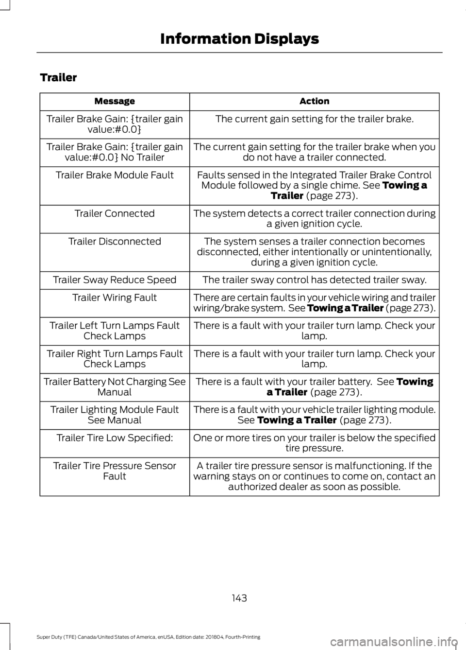
Trailer
Action
Message
The current gain setting for the trailer brake.
Trailer Brake Gain: {trailer gain
value:#0.0}
The current gain setting for the trailer brake when youdo not have a trailer connected.
Trailer Brake Gain: {trailer gain
value:#0.0} No Trailer
Faults sensed in the Integrated Trailer Brake ControlModule followed by a single chime. See Towing a
Trailer (page 273).
Trailer Brake Module Fault
The system detects a correct trailer connection duringa given ignition cycle.
Trailer Connected
The system senses a trailer connection becomes
disconnected, either intentionally or unintentionally, during a given ignition cycle.
Trailer Disconnected
The trailer sway control has detected trailer sway.
Trailer Sway Reduce Speed
There are certain faults in your vehicle wiring and trailer
wiring/brake system. See Towing a Trailer
(page 273).
Trailer Wiring Fault
There is a fault with your trailer turn lamp. Check yourlamp.
Trailer Left Turn Lamps Fault
Check Lamps
There is a fault with your trailer turn lamp. Check yourlamp.
Trailer Right Turn Lamps Fault
Check Lamps
There is a fault with your trailer battery. See
Towing
a Trailer (page 273).
Trailer Battery Not Charging See
Manual
There is a fault with your vehicle trailer lighting module.See
Towing a Trailer (page 273).
Trailer Lighting Module Fault
See Manual
One or more tires on your trailer is below the specifiedtire pressure.
Trailer Tire Low Specified:
A trailer tire pressure sensor is malfunctioning. If the
warning stays on or continues to come on, contact an authorized dealer as soon as possible.
Trailer Tire Pressure Sensor
Fault
143
Super Duty (TFE) Canada/United States of America, enUSA, Edition date: 201804, Fourth-Printing Information Displays
Page 172 of 666
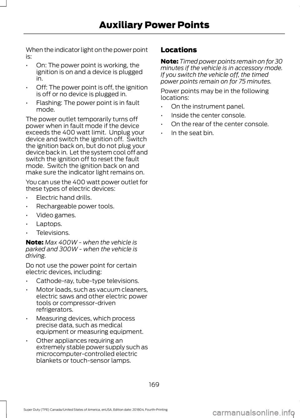
When the indicator light on the power point
is:
•
On: The power point is working, the
ignition is on and a device is plugged
in.
• Off: The power point is off, the ignition
is off or no device is plugged in.
• Flashing: The power point is in fault
mode.
The power outlet temporarily turns off
power when in fault mode if the device
exceeds the 400 watt limit. Unplug your
device and switch the ignition off. Switch
the ignition back on, but do not plug your
device back in. Let the system cool off and
switch the ignition off to reset the fault
mode. Switch the ignition back on and
make sure the indicator light remains on.
You can use the 400 watt power outlet for
these types of electric devices:
• Electric hand drills.
• Rechargeable power tools.
• Video games.
• Laptops.
• Televisions.
Note: Max 400W - when the vehicle is
parked and 300W - when the vehicle is
driving.
Do not use the power point for certain
electric devices, including:
• Cathode-ray, tube-type televisions.
• Motor loads, such as vacuum cleaners,
electric saws and other electric power
tools or compressor-driven
refrigerators.
• Measuring devices, which process
precise data, such as medical
equipment or measuring equipment.
• Other appliances requiring an
extremely stable power supply such as
microcomputer-controlled electric
blankets or touch-sensor lamps. Locations
Note:
Timed power points remain on for 30
minutes if the vehicle is in accessory mode.
If you switch the vehicle off, the timed
power points remain on for 75 minutes.
Power points may be in the following
locations:
• On the instrument panel.
• Inside the center console.
• On the rear of the center console.
• In the seat bin.
169
Super Duty (TFE) Canada/United States of America, enUSA, Edition date: 201804, Fourth-Printing Auxiliary Power Points
Page 180 of 666
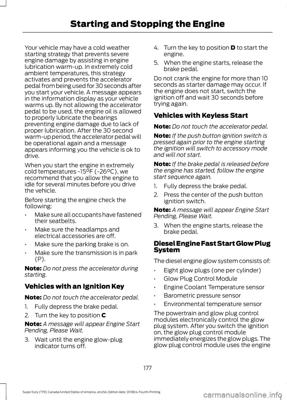
Your vehicle may have a cold weather
starting strategy that prevents severe
engine damage by assisting in engine
lubrication warm-up. In extremely cold
ambient temperatures, this strategy
activates and prevents the accelerator
pedal from being used for 30 seconds after
you start your vehicle. A message appears
in the information display as your vehicle
warms up. By not allowing the accelerator
pedal to be used, the engine oil is allowed
to properly lubricate the bearings
preventing engine damage due to lack of
proper lubrication. After the 30 second
warm-up period, the accelerator pedal will
be operational again and a message
appears informing you the vehicle is ok to
drive.
When you start the engine in extremely
cold temperatures -15°F (-26°C), we
recommend that you allow the engine to
idle for several minutes before you drive
the vehicle.
Before starting the engine check the
following:
• Make sure all occupants have fastened
their seatbelts.
• Make sure the headlamps and
electrical accessories are off.
• Make sure the parking brake is on.
• Make sure the transmission is in park
(P).
Note: Do not press the accelerator during
starting.
Vehicles with an Ignition Key
Note: Do not touch the accelerator pedal.
1. Fully depress the brake pedal.
2. Turn the key to position
C
Note: A message will appear Engine Start
Pending, Please Wait.
3. Wait until the engine glow-plug indicator turns off. 4. Turn the key to position
D to start the
engine.
5. When the engine starts, release the brake pedal.
Do not crank the engine for more than 10
seconds as starter damage may occur. If
the engine does not start, switch the
ignition off and wait 30 seconds before
trying again.
Vehicles with Keyless Start
Note: Do not touch the accelerator pedal.
Note: If the push button ignition switch is
pressed again prior to the engine starting
the ignition will switch to accessory mode
and will not start.
Note: If the brake pedal is released before
the engine has started, follow the engine
start sequence again.
1. Fully depress the brake pedal.
2. Press the center of the push button ignition switch.
Note: A message will appear Engine Start
Pending, Please Wait.
3. When the engine starts, release the brake pedal.
Diesel Engine Fast Start Glow Plug
System
The diesel engine glow system consists of:
• Eight glow plugs (one per cylinder)
• Glow Plug Control Module
• Engine Coolant Temperature sensor
• Barometric pressure sensor
• Environmental temperature sensor
The powertrain and glow plug control
modules electronically control the glow
plug system. After you switch the ignition
on, the glow plug control module
immediately energizes the glow plugs. The
glow plug control module uses the engine
177
Super Duty (TFE) Canada/United States of America, enUSA, Edition date: 201804, Fourth-Printing Starting and Stopping the Engine
Page 181 of 666
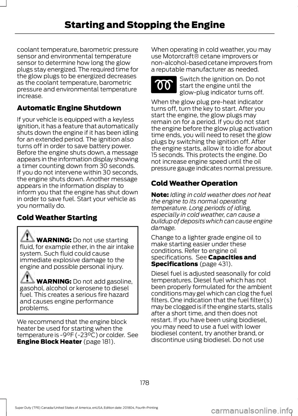
coolant temperature, barometric pressure
sensor and environmental temperature
sensor to determine how long the glow
plugs stay energized. The required time for
the glow plugs to be energized decreases
as the coolant temperature, barometric
pressure and environmental temperature
increase.
Automatic Engine Shutdown
If your vehicle is equipped with a keyless
ignition, it has a feature that automatically
shuts down the engine if it has been idling
for an extended period. The ignition also
turns off in order to save battery power.
Before the engine shuts down, a message
appears in the information display showing
a timer counting down from 30 seconds.
If you do not intervene within 30 seconds,
the engine shuts down. Another message
appears in the information display to
inform you that the engine has shut down
in order to save fuel. Start your vehicle as
you normally do.
Cold Weather Starting
WARNING: Do not use starting
fluid, for example ether, in the air intake
system. Such fluid could cause
immediate explosive damage to the
engine and possible personal injury. WARNING:
Do not add gasoline,
gasohol, alcohol or kerosene to diesel
fuel. This creates a serious fire hazard
and causes engine performance
problems.
We recommend that the engine block
heater be used for starting when the
temperature is -9°F (-23°C) or colder. See
Engine Block Heater
(page 181). When operating in cold weather, you may
use Motorcraft® cetane improvers or
non-alcohol-based cetane improvers from
a reputable manufacturer as needed. Switch the ignition on. Do not
start the engine until the
glow-plug indicator turns off.
When the glow plug pre-heat indicator
turns off, turn the key to start. After you
start the engine, the glow plugs may
remain on for a period. If you do not start
the engine before the glow plug activation
time ends, you will need to reset the glow
plugs by switching the ignition off. After
the engine starts, allow it to idle for about
15 seconds. This protects the engine. Do
not increase engine speed until the oil
pressure gauge indicates normal pressure.
Cold Weather Operation
Note: Idling in cold weather does not heat
the engine to its normal operating
temperature. Long periods of idling,
especially in cold weather, can cause a
buildup of deposits which can cause engine
damage.
Change to a lighter grade engine oil to
make starting easier under these
conditions. Refer to engine oil
specifications. See
Capacities and
Specifications (page 431).
Diesel fuel is adjusted seasonally for cold
temperatures. Diesel fuel which has not
been properly formulated for the ambient
conditions may gel which can clog the fuel
filters. One indication that the fuel filter(s)
may be clogged is if the engine starts, stalls
after a short time, and then does not
restart. If you have been using biodiesel,
you may need to use a fuel with lower
biodiesel content, try another brand, or
discontinue using biodiesel. Do not use
178
Super Duty (TFE) Canada/United States of America, enUSA, Edition date: 201804, Fourth-Printing Starting and Stopping the Engine
Page 196 of 666
EMISSION LAW
WARNING: Do not remove or alter
the original equipment floor covering or
insulation between it and the metal floor
of the vehicle. The floor covering and
insulation protect occupants of the
vehicle from the engine and exhaust
system heat and noise. On vehicles with
no original equipment floor covering
insulation, do not carry passengers in a
manner that permits prolonged skin
contact with the metal floor. Failure to
follow these instructions may result in
fire or personal injury.
U.S. federal laws and certain state laws
prohibit removing or rendering inoperative
emission control system components.
Similar federal or provincial laws may
apply in Canada. We do not approve of any
vehicle modification without first
determining applicable laws. Tampering with emissions
control systems including
related sensors or the Diesel
Exhaust Fluid system can result in reduced
engine power and the illumination of the
service engine soon light. Tampering With a Noise Control
System
Federal laws prohibit the following acts:
•
Removal or rendering inoperative by
any person other than for purposes of
maintenance.
• Repair or replacement of any device or
element of the design incorporated into
a new vehicle for the purpose of noise
control prior to its sale or delivery to
the ultimate purchaser or while it is in
use.
• The use of the vehicle after any person
removes or renders inoperative any
device or element of the design.
The U.S. Environmental Protection Agency
may presume to constitute tampering as
follows:
• Removal of hood blanket, fender apron
absorbers, fender apron barriers,
underbody noise shields or acoustically
absorptive material.
• Tampering or rendering inoperative the
engine speed governor, to allow engine
speed to exceed manufacturer
specifications.
If the engine does not start, runs rough,
experiences a decrease in engine
performance, experiences excess fuel
consumption or produces excessive
exhaust smoke, check for the following:
• A plugged or disconnected air inlet
system hose.
• A plugged engine air filter element.
• Water in the fuel filter and water
separator.
• A clogged fuel filter.
• Contaminated fuel.
• Air in the fuel system, due to loose
connections.
• An open or pinched sensor hose.
• Incorrect engine oil level.
193
Super Duty (TFE) Canada/United States of America, enUSA, Edition date: 201804, Fourth-Printing Engine Emission Control
Page 203 of 666
•
The system has a diesel exhaust fluid
quality sensor. Dilution of diesel
exhaust fluid or use of any other liquid
in the SCR system leads to a diesel
exhaust fluid system fault, eventually
leading to the vehicle only operating in
idle-only mode.
• Do not dilute diesel exhaust fluid with
water or any other liquid.
• An ammonia odor may be smelled
when the cap is removed or during
refill. Refill diesel exhaust fluid in a well
ventilated area.
Typical Diesel Exhaust Fluid Usage
When Using the Power Take Off (PTO) Continuous PTO use—Minimal PTO use
0–7,800 mi (0– 12,550 km)
Contaminated Diesel Exhaust
Fluid or Inoperative Selective
Catalytic Reduction System
Selective catalytic reduction systems are
sensitive to contamination of the diesel
exhaust fluid. Maintaining the purity of the
fluid is important to avoid system
malfunctions. If you remove or drain the
diesel exhaust fluid tank, do not use the
same fluid to refill the tank. The system
has a sensor to monitor fluid quality. A warning lamp illuminates and
a message appears in the
information display if the system
becomes contaminated or inoperative. Continued driving without replacing diesel
exhaust fluid or having the selective
catalytic reduction system repaired results
in the following actions as required by the
California Air Resources Board (CARB) and
U.S. Environmental Protection Agency
(EPA):
•
Within a preset distance to empty,
speed is limited upon vehicle restart.
Prior to this occurring a message
appears in the information display.
• Further vehicle operation without
replacing contaminated diesel exhaust
fluid causes the engine to enter an
idle-only condition. This only occurs
upon vehicle refueling, vehicle idling in
park for 1 hour, or engine shutdown for
10 minutes or more and is indicated by
a message in the information display
indicating required actions to resume
normal operation.
Note: For vehicle speed limiting or idle-only
condition, normal vehicle operation resumes
when you repair the contaminated system.
To service a contaminated or inoperative
system, see an authorized dealer.
DIESEL PARTICULATE FILTER
The filter forms part of the emissions
reduction system on your vehicle. It filters
harmful diesel particulates (soot) from the
exhaust gas.
Regeneration WARNING: Do not park or idle your
vehicle over dry leaves, dry grass or other
combustible materials. The regeneration
process creates very high exhaust gas
temperatures and the exhaust will
radiate a considerable amount of heat
during and after regeneration and after
you have switched the engine off. This is
a potential fire hazard.
200
Super Duty (TFE) Canada/United States of America, enUSA, Edition date: 201804, Fourth-Printing Engine Emission ControlE163176
Page 229 of 666
When the system is active, your vehicle
remains stationary on the slope for two to
three seconds after you release the brake
pedal. This allows time to move your foot
from the brake to the accelerator pedal.
The system releases the brakes
automatically once the engine has
developed sufficient torque to prevent your
vehicle from rolling down the slope. This
is an advantage when pulling away on a
slope, for example from a car park ramp,
traffic lights or when reversing uphill into
a parking space.
The system activates on any slope that
causes your vehicle to roll.
Note:
There is no warning light to indicate
the system is either on or off.
Using Hill Start Assist
1. Press the brake pedal to bring your vehicle to a complete standstill. Keep
the brake pedal pressed and shift into
first gear when facing uphill or reverse
(R) when facing downhill.
2. If the sensors detect that your vehicle is on a slope, the system activates
automatically.
3. When you remove your foot from the brake pedal, your vehicle remains on
the slope without rolling away for
about two to three seconds. This hold
time automatically extends if you are
in the process of driving off.
4. Drive off in the normal manner. The system releases the brakes
automatically.
Note: When you remove your foot from the
brake pedal and press the pedal again when
the system is active, you will experience
significantly reduced brake pedal travel. This
is normal. Switching the System On and Off
Vehicles with Manual Transmission
You can switch this feature on or off in the
information display. The system
remembers the last setting when you start
your vehicle.
Vehicles with Automatic Transmission
You cannot turn the system on or off.
When you switch the ignition on, the
system automatically turns on.
226
Super Duty (TFE) Canada/United States of America, enUSA, Edition date: 201804, Fourth-Printing Brakes
Page 231 of 666
PRINCIPLE OF OPERATION
WARNING: Vehicle modifications
involving braking system, aftermarket
roof racks, suspension, steering system,
tire construction and wheel and tire size
may change the handling characteristics
of your vehicle and may adversely affect
the performance of the electronic
stability control system. In addition,
installing any stereo loudspeakers may
interfere with and adversely affect the
electronic stability control system. Install
any aftermarket stereo loudspeaker as
far as possible from the front center
console, the tunnel, and the front seats
in order to minimize the risk of interfering
with the electronic stability control
sensors. Reducing the effectiveness of
the electronic stability control system
could lead to an increased risk of loss of
vehicle control, vehicle rollover, personal
injury and death. WARNING:
Remember that even
advanced technology cannot defy the
laws of physics. It’ s always possible to
lose control of a vehicle due to
inappropriate driver input for the
conditions. Aggressive driving on any
road condition can cause you to lose
control of your vehicle increasing the risk
of personal injury or property damage.
Activation of the electronic stability
control system is an indication that at
least some of the tires have exceeded
their ability to grip the road; this could
reduce the operator ’s ability to control
the vehicle potentially resulting in a loss
of vehicle control, vehicle rollover,
personal injury and death. If your
electronic stability control system
activates, SLOW DOWN.
The system automatically turns on each
time you switch the ignition on. If a fault occurs in either the stability
control or the traction control system, you
may experience the following conditions:
•
The stability and traction control light
illuminates steadily.
• The stability control and traction
control systems do not enhance your
vehicle's ability to maintain traction of
the wheels.
• The Adaptive Steering system (if
equipped) automatically changes the
steering function to a fixed steering
ratio. See
Steering (page 260).
If a driving condition activates either the
stability control or the traction control
system you may experience the following
conditions:
• The stability and traction control light
flashes.
• Your vehicle slows down.
• Reduced engine power.
• A vibration in the brake pedal.
• The brake pedal is stiffer than usual.
• If the driving condition is severe and
your foot is not on the brake, the brake
pedal may move as the system applies
higher brake force.
The stability control system has several
features built into it to help you maintain
control of your vehicle:
Electronic Stability Control
The system enhances your vehicle ’s ability
to prevent skids or lateral slides by
applying brakes to one or more of the
wheels individually and, if necessary,
reducing engine power.
228
Super Duty (TFE) Canada/United States of America, enUSA, Edition date: 201804, Fourth-Printing Stability Control
Page 236 of 666
PRINCIPLE OF OPERATION
WARNING: To help avoid personal
injury, always use caution when in
reverse (R) and when using the sensing
system. WARNING: The system may not
detect objects with surfaces that absorb
reflection. Always drive with due care
and attention. Failure to take care may
result in a crash. WARNING:
Traffic control
systems, inclement weather, air brakes,
external motors and fans may affect the
correct operation of the sensing
system.This may cause reduced
performance or false alerts. WARNING:
The system may not
detect small or moving objects,
particularly those close to the ground.
Note: Certain add-on devices installed
around the bumper or fascia may create
false beeps. For example, large trailer
hitches, bike or surfboard racks, license plate
brackets, bumper covers or any other device
that may block the normal detection zone
of the system.
Note: Keep the sensors, located on the
bumper or fascia, free from snow, ice and
large accumulations of dirt. If the sensors
are covered, the system ’s accuracy can be
affected. Do not clean the sensors with
sharp objects.
Note: If your vehicle sustains damage to
the bumper or fascia, leaving it misaligned
or bent, the sensing zone may be altered
causing inaccurate measurement of
obstacles or false alarms. See your
authorized technician. Note:
When a trailer is connected to your
vehicle, the rear parking aid may detect the
trailer and therefore provide warnings.
Disable the rear parking aid when a trailer
is connected to prevent these warnings.
Note: The sensing system cannot be turned
off when a MyKey is present. See Principle
of Operation
(page 65).
The sensing system warns the driver of
obstacles within a certain range of your
vehicle. The system turns on automatically
whenever you switch the ignition on.
When receiving a detection warning, the
radio volume reduces to a predetermined
level. After the warning goes away, the
radio volume returns to the previous level.
The sensing system can be switched off
through the information display menu or
from the pop-up message that appears
once you shift the transmission into reverse
(R). See General Information (page 112).
If a fault is present in the system, a warning
message appears in the information
display and you cannot switch the system
on through the pop-up message. See
Information Messages
(page 128).
REAR PARKING AID
(IF EQUIPPED)
The rear sensors are only active when the
transmission is in reverse (R). As your
vehicle moves closer to the obstacle, the
rate of the audible warning increases.
When the obstacle is less than
11.81 in
(30 cm) away, the warning sounds
continuously. If the system detects a
stationary or receding object farther than
11.81 in (30 cm)
from the corners of the
bumper, the tone sounds for only two
seconds. Once the system detects an
object approaching, the warning sounds
again.
233
Super Duty (TFE) Canada/United States of America, enUSA, Edition date: 201804, Fourth-Printing Parking Aids
Page 239 of 666
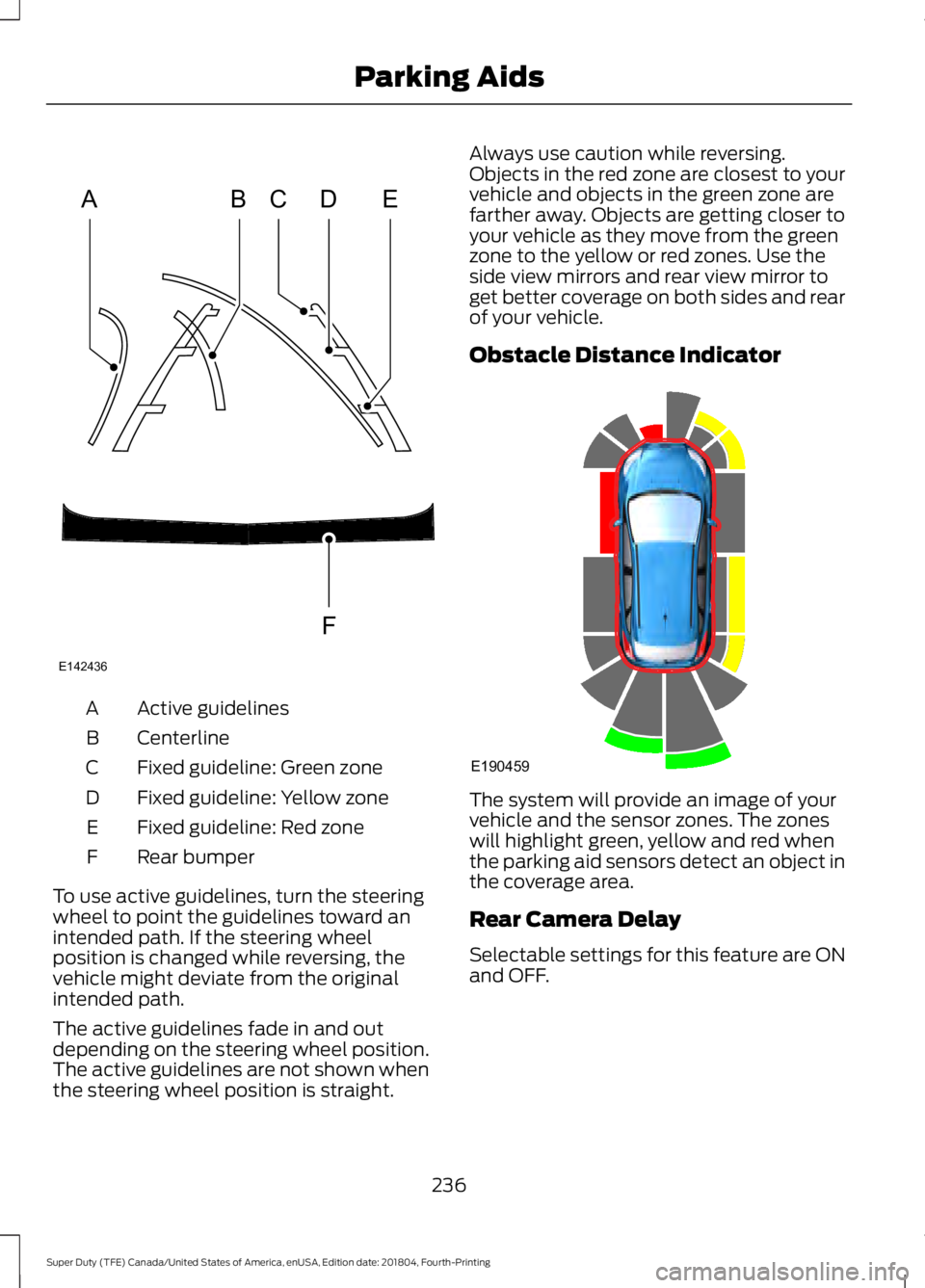
Active guidelines
A
Centerline
B
Fixed guideline: Green zone
C
Fixed guideline: Yellow zone
D
Fixed guideline: Red zone
E
Rear bumper
F
To use active guidelines, turn the steering
wheel to point the guidelines toward an
intended path. If the steering wheel
position is changed while reversing, the
vehicle might deviate from the original
intended path.
The active guidelines fade in and out
depending on the steering wheel position.
The active guidelines are not shown when
the steering wheel position is straight. Always use caution while reversing.
Objects in the red zone are closest to your
vehicle and objects in the green zone are
farther away. Objects are getting closer to
your vehicle as they move from the green
zone to the yellow or red zones. Use the
side view mirrors and rear view mirror to
get better coverage on both sides and rear
of your vehicle.
Obstacle Distance Indicator
The system will provide an image of your
vehicle and the sensor zones. The zones
will highlight green, yellow and red when
the parking aid sensors detect an object in
the coverage area.
Rear Camera Delay
Selectable settings for this feature are ON
and OFF.
236
Super Duty (TFE) Canada/United States of America, enUSA, Edition date: 201804, Fourth-Printing Parking AidsABCD
F
E
E142436 E190459