AUX FORD F-450 2020 User Guide
[x] Cancel search | Manufacturer: FORD, Model Year: 2020, Model line: F-450, Model: FORD F-450 2020Pages: 631, PDF Size: 9.62 MB
Page 238 of 631
Access the auxiliary camera view
by pressing the button on the
display screen when in reverse
(R).
Access the auxiliary camera while in drive
(D) by pressing the camera button twice.
The auxiliary camera system is a variant
of the rear view camera. It is designed to
display a rear view image from the back of
a trailer while reversing. The auxiliary
camera is not meant as an alternative to
the rear view camera.
235
Super Duty (TFE), enUSA, Edition date: 201909, Third-Printing- Parking Aids (If Equipped)E233727
Page 284 of 631
4. When in this mode, you can see the
camera view on the side your trailer is
moving, or both sides when the trailer
is straight behind you. When the views
change with the trailer direction, it is
called auto mode. For example, if you
turn the trailer to the right, you see the
right side of your vehicle and trailer.
You can manually switch this view at
any time by using the arrow keys. To
return to auto mode, press the auto
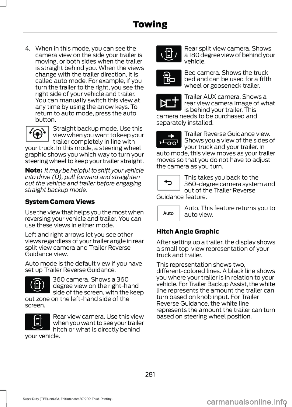
button. Straight backup mode. Use this
view when you want to keep your
trailer completely in line with
your truck. In this mode, a steering wheel
graphic shows you which way to turn your
steering wheel to keep your trailer straight.
Note: It may be helpful to shift your vehicle
into drive (D), pull forward and straighten
out the vehicle and trailer before engaging
straight backup mode.
System Camera Views
Use the view that helps you the most when
reversing your vehicle and trailer. You can
use these views in either mode.
Left and right arrows let you see other
views regardless of your trailer angle in rear
split view camera and Trailer Reverse
Guidance view.
Auto mode is the default view if you have
set up Trailer Reverse Guidance. 360 camera. Shows a 360
degree view on the right-hand
side of the screen, with the keep
out zone on the left-hand side of the
screen. Rear view camera. Use this view
when you want to see your trailer
hitch or what is directly behind
your vehicle. Rear split view camera. Shows
a 180 degree view of behind your
vehicle.
Bed camera. Shows the truck
bed and can be used for a fifth
wheel or gooseneck trailer.
Trailer AUX camera. Shows a
rear view camera image of what
is behind your trailer. This
camera needs to be purchased and
separately installed. Trailer Reverse Guidance view.
Shows you a view of the sides of
your truck and your trailer. In
auto mode, this view moves as your trailer
moves so that you do not have to adjust
the camera as you turn. This takes you back to the
360-degree camera system and
out of the Trailer Reverse
Guidance feature. Auto. This feature returns you to
auto view.
Hitch Angle Graphic
After setting up a trailer, the display shows
a small top-view representation of your
truck and trailer.
This representation shows two,
different-colored lines. A black line shows
you where your trailer is in relation to your
vehicle. For Trailer Backup Assist, the white
line represents the amount the trailer can
turn based on knob input. For Trailer
Reverse Guidance, the white line
represents the amount the trailer can turn
based on steering wheel position.
281
Super Duty (TFE), enUSA, Edition date: 201909, Third-Printing- TowingE224484 E310996 E310967 E310974 E310995 E311776 E310965 E224486 E315644
Page 314 of 631
For Vehicles with Tremor Off-Road
Package
Your vehicle equipped with Tremor
Off-Road package is capable of traveling
through water at a maximum depth of
33 in (837 mm). When driving through
standing water do not exceed crawl speed
of
4 mph (7 km/h).
• Always determine the depth before
attempting a water crossing.
• Proceed slowly and avoid splashing
water any more than is necessary. As
the water depth increases, vehicle
speed must be reduced to avoid
potential vehicle damage.
• Be aware that obstacles and debris
may be beneath the water ’s surface.
• Keep the doors fully closed during the
water crossing.
• Upon completion of the water crossing,
slowly drive a short distance and check
the brakes for full effectiveness.
SNOW PLOWING
Ford recommends that the Super Duty
F-Series used for snow removal include
the snowplow package option.
Installing the Snowplow
Weight limits and guidelines for selecting
and installing the snowplow are in the Ford
Truck Body Builders Layout Book,
snowplow section, found at
www.fleet.ford.com/truckbbas. A typical
installation affects the following: •
Certification to government safety laws
such as occupant protection and airbag
deployment, braking, and lighting. Look
for an Alterer ’s Label on the vehicle
from the snowplow installer certifying
that the installation meets all
applicable Federal Motor Vehicle
Safety Standards (FMVSS).
• The Total Accessory Reserve Capacity
(TARC) is on the lower right side of the
vehicle ’s Safety Compliance
Certification Label. This applies to
Ford-completed vehicles of
10,000 lb
(4,536 kg) GVWR or less. This is the
weight of permanently-attached
auxiliary equipment, such as snowplow
frame-mounting hardware, that can
be added to the vehicle and satisfy
Ford compliance certification to
FMVSS. Exceeding this weight may
require the auxiliary equipment installer
additional safety certification
responsibility. The Front Accessory
Reserve Capacity (FARC) is for
customer convenience.
• Rear ballast weight behind the rear
axle may be required to prevent
exceeding the FGAWR, and provide
front-to-rear weight balance for proper
braking and steering.
• Front wheel toe may require
re-adjustment to prevent premature
uneven tire wear. Specifications are in
the Ford Workshop Manual.
• Headlight aim may require
re-adjustment.
311
Super Duty (TFE), enUSA, Edition date: 201909, Third-Printing- Driving Hints
Page 335 of 631
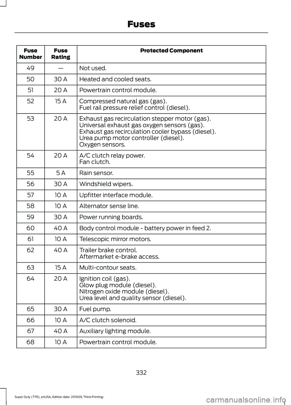
Protected Component
Fuse
Rating
Fuse
Number
Not used.
—
49
Heated and cooled seats.
30 A
50
Powertrain control module.
20 A
51
Compressed natural gas (gas).
15 A
52
Fuel rail pressure relief control (diesel).
Exhaust gas recirculation stepper motor (gas).
20 A
53
Universal exhaust gas oxygen sensors (gas).
Exhaust gas recirculation cooler bypass (diesel).
Urea pump motor controller (diesel).
Oxygen sensors.
A/C clutch relay power.
20 A
54
Fan clutch.
Rain sensor.
5 A
55
Windshield wipers.
30 A
56
Upfitter interface module.
10 A
57
Alternator sense line.
10 A
58
Power running boards.
30 A
59
Body control module - battery power in feed 2.
40 A
60
Telescopic mirror motors.
10 A
61
Trailer brake control.
40 A
62
Aftermarket e-brake access.
Multi-contour seats.
15 A
63
Ignition coil (gas).
20 A
64
Glow plug module (diesel).
Nitrogen oxide module (diesel).
Urea level and quality sensor (diesel).
Fuel pump.
30 A
65
A/C clutch solenoid.
10 A
66
Auxiliary lighting module.
40 A
67
Powertrain control module.
10 A
68
332
Super Duty (TFE), enUSA, Edition date: 201909, Third-Printing- Fuses
Page 351 of 631
4. Remove the auxiliary foam filter from
the air filter housing.
5. To install, reverse the removal procedure. The housing cover can be
oscillated slightly left to right to assist
with installation as needed, until
positioned such that all three clips can
be re-engaged.
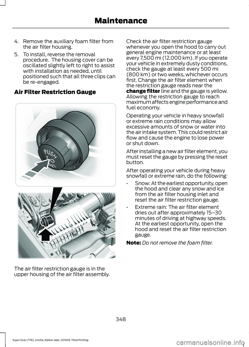
Air Filter Restriction Gauge The air filter restriction gauge is in the
upper housing of the air filter assembly. Check the air filter restriction gauge
whenever you open the hood to carry out
general engine maintenance or at least
every 7,500 mi (12,000 km). If you operate
your vehicle in extremely dusty conditions,
check the gauge at least every 500 mi
(800 km) or two weeks, whichever occurs
first. Change the air filter element when
the restriction gauge reads near the
change filter line and the gauge is yellow.
Allowing the restriction gauge to reach
maximum affects engine performance and
fuel economy.
Operating your vehicle in heavy snowfall
or extreme rain conditions may allow
excessive amounts of snow or water into
the air intake system. This could restrict air
flow and cause the engine to lose power
or shut down.
After installing a new air filter element, you
must reset the gauge by pressing the reset
button.
After operating your vehicle during heavy
snowfall or extreme rain, do the following:
• Snow: At the earliest opportunity, open
the hood and clear any snow and ice
from the air filter housing inlet and
reset the air filter restriction gauge.
• Extreme rain: The air filter element
dries out after approximately 15– 30
minutes of driving at highway speeds.
At the earliest opportunity, open the
hood and reset the air filter restriction
gauge.
Note: Do not remove the foam filter.
348
Super Duty (TFE), enUSA, Edition date: 201909, Third-Printing- Maintenance E310420
Page 486 of 631
USB PORT
WARNING: Driving while distracted
can result in loss of vehicle control, crash
and injury. We strongly recommend that
you use extreme caution when using any
device that may take your focus off the
road. Your primary responsibility is the
safe operation of your vehicle. We
recommend against the use of any
hand-held device while driving and
encourage the use of voice-operated
systems when possible. Make sure you
are aware of all applicable local laws
that may affect the use of electronic
devices while driving.
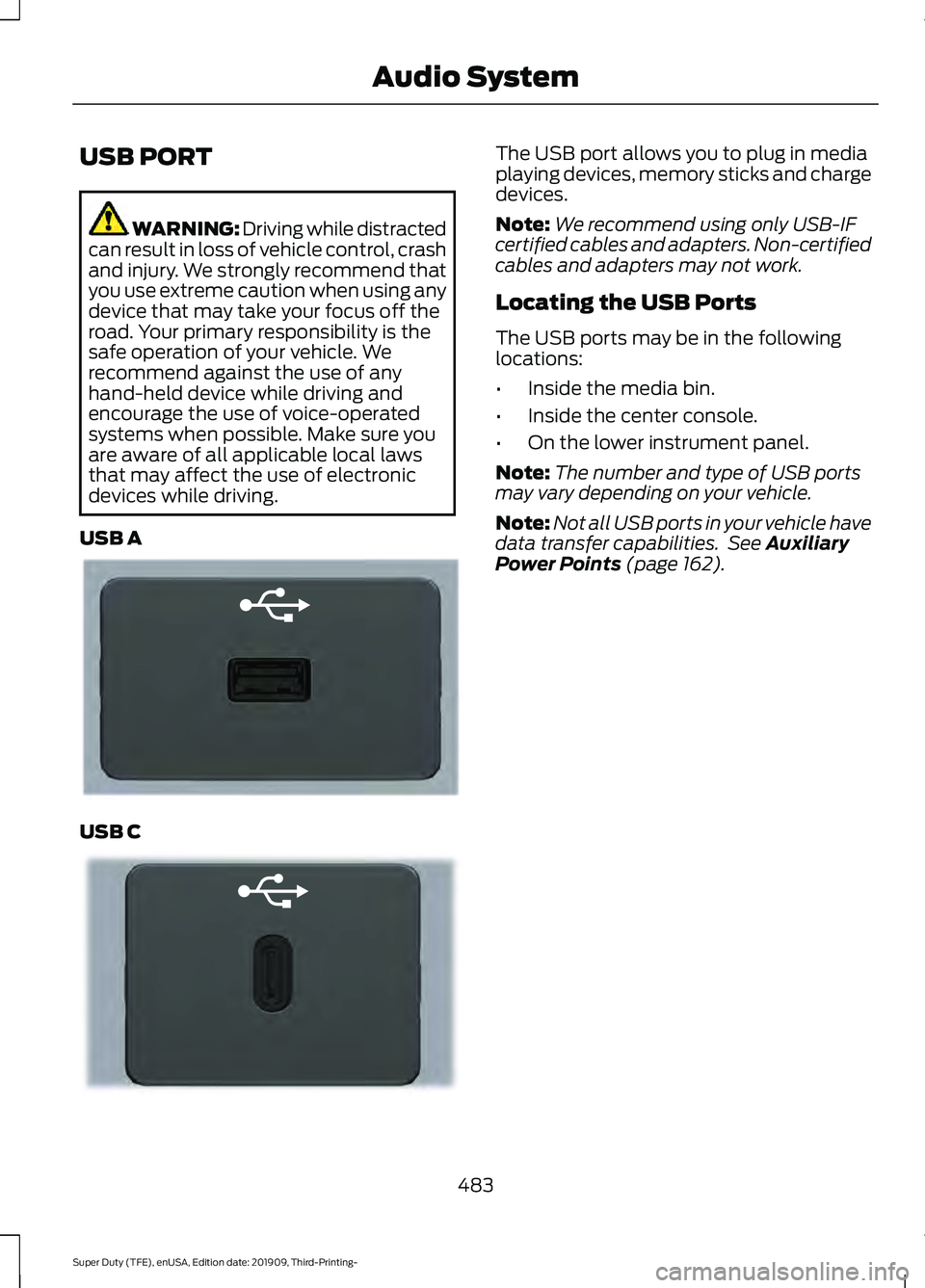
USB A USB C The USB port allows you to plug in media
playing devices, memory sticks and charge
devices.
Note:
We recommend using only USB-IF
certified cables and adapters. Non-certified
cables and adapters may not work.
Locating the USB Ports
The USB ports may be in the following
locations:
• Inside the media bin.
• Inside the center console.
• On the lower instrument panel.
Note: The number and type of USB ports
may vary depending on your vehicle.
Note: Not all USB ports in your vehicle have
data transfer capabilities. See Auxiliary
Power Points (page 162).
483
Super Duty (TFE), enUSA, Edition date: 201909, Third-Printing- Audio SystemE201595 E301114
Page 494 of 631
App Permissions
App permissions are organized by groups.
You can grant these group permissions
individually. You can change a permission
group status any time when not driving, by
using the settings menu.
When you launch an app using SYNC, the
system may ask you to grant certain
permissions, for example:
•
To allow your vehicle to provide vehicle
information to the app such as, but not
limited to: Fuel level, fuel economy, fuel
consumption, engine speed, rain
sensor, odometer, VIN, external
temperature, gear position, tire
pressure, and head lamp status.
• To allow your vehicle to provide driving
characteristic information such as, but
not limited to: MyKey, seat belt status,
engine revolutions per minute, gear
position, braking events, steering wheel
angle, and accelerator pedal position.
• To allow your vehicle to provide
location information, including: GPS
and speed.
• To allow the app to send push
notifications using the vehicle display
and voice capabilities while running in
a background state. Push notifications
may be particularly useful for news or
location based apps.
Note: You only need to grant permissions
the first time you use an app with SYNC.
Note: Ford is not responsible or liable for
any damages or loss of privacy relating to
usage of an app, or dissemination of any
vehicle data that you approve Ford to
provide to an app. Enabling SYNC Mobile Apps
In order to enable mobile apps, SYNC
requires user consent to send and receive
app authorization information and updates
using the data plan associated with the
connected device.
Data is sent to Ford in the United States
through the connected device. The
information is encrypted and includes your
VIN, SYNC module number, anonymous
usage statistics and debugging
information. Updates may take place.
Note:
You must enable mobile apps for
each connected device the first time you
select a mobile app using the system.
Note: Standard data rates apply. Ford is
not responsible for any additional charges
you may receive from your service provider,
when your vehicle sends or receives data
through the connected device. This includes
any additional charges incurred due to
driving in areas when roaming out of a home
network.
USING SYNC™ WITH YOUR
MEDIA PLAYER
SYNC supports digital media sources
including: iPod, Bluetooth devices, and
most USB drives. SYNC also supports
audio formats, such as MP3, WMA, WAV
and ACC.
Media Sources
The AUX or MEDIA button allows you to
view and select available media sources.
Press the
AUX or MEDIA button to view
your sources. Use the directional arrows
and OK button to select your source. You
can also use the steering wheel audio
controls.
491
Super Duty (TFE), enUSA, Edition date: 201909, Third-Printing- SYNC™
(If Equipped)
Page 550 of 631

AUXILIARY SWITCHES
For maximum vehicle performance, keep
the following information in mind when
adding accessories or equipment to your
vehicle:
•
When adding accessories, equipment,
passengers and luggage to your
vehicle, do not exceed the total weight
capacity of the vehicle or of the front
or rear axle (GVWR or GAWR as
indicated on the Safety Compliance
Certification label). Ask an authorized
dealer for specific weight information.
• The Federal Communications
Commission (FCC) and Canadian
Radio Telecommunications
Commission (CRTC) regulate the use
of mobile communications systems
equipped with radio transmitters, for
example, two-way radios, telephones
and theft alarms. Any such equipment
installed in your vehicle should comply
with Federal Communications
Commission (FCC) and Canadian
Radio Telecommunications
Commission (CRTC) regulations, and
should be installed by an authorized
dealer.
• An authorized dealer needs to install
mobile communications systems.
Improper installation may harm the
operation of your vehicle, particularly
if the manufacturer did not design the
mobile communication system
specifically for automotive use.
• If you or an authorized Ford dealer add
any non-Ford electrical or electronic
accessories or components to your
vehicle, you may adversely affect
battery performance and durability. In
addition, you may also adversely affect
the performance of other electrical
systems in the vehicle. The auxiliary switch option package
provides six switches mounted in the
overhead console. These switches operate
when the vehicle is running or from battery
power, depending on the switchable fuse
AUXF4's location in the upfitter relay box.
We recommend, however, that the engine
remain running to maintain battery charge
when using the auxiliary switches for
extended periods of time or higher current
draws.
Note:
When your vehicle has a diesel
engine, use the auxiliary switches only when
the engine is running. The glow plugs also
drain battery power when the ignition key is
in the on position. Using the auxiliary
switches, even for limited amounts of time,
can cause your battery to drain quickly and
prevent your vehicle from restarting.
When switched on, the auxiliary switches
provide electrical battery power for a
variety of personal or commercial uses.
Switches 1 through 4 provide 25 amps.
Switches 5 and 6 provide 40 amps.
The relay box for the auxiliary switches is
in the engine compartment. See your
authorized dealer for service.
The relays are coded as shown:
547
Super Duty (TFE), enUSA, Edition date: 201909, Third-Printing- AccessoriesE220728
Page 552 of 631
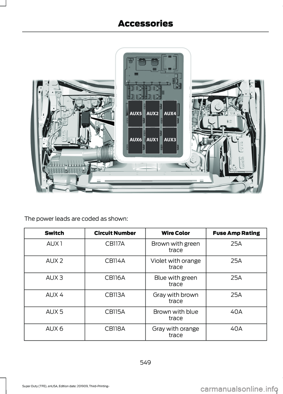
The power leads are coded as shown:
Fuse Amp Rating
Wire Color
Circuit Number
Switch
25A
Brown with green
trace
CB117A
AUX 1
25A
Violet with orange
trace
CB114A
AUX 2
25A
Blue with green
trace
CB116A
AUX 3
25A
Gray with brown
trace
CB113A
AUX 4
40A
Brown with blue
trace
CB115A
AUX 5
40A
Gray with orange
trace
CB118A
AUX 6
549
Super Duty (TFE), enUSA, Edition date: 201909, Third-Printing- AccessoriesE314958
Page 553 of 631
Upfitter Interface Module (If Equipped)
The Upfitter Interface Module (UIM) is an
electronic control module that operates
equipment (such as lift buckets, cranes,
motors, salt spreaders and snow plows)
with external relays.
If you replace the module, it will require
additional programming by the upfitter.
Obtain this data directly from the upfitter
company. The upfitter contact information
is in the vehicle door opening.
For more information on the Upfitter
Interface Module and the auxiliary
switches, contact your upfitter.
550
Super Duty (TFE), enUSA, Edition date: 201909, Third-Printing- Accessories