height FORD F-450 2020 User Guide
[x] Cancel search | Manufacturer: FORD, Model Year: 2020, Model line: F-450, Model: FORD F-450 2020Pages: 631, PDF Size: 9.62 MB
Page 286 of 631
Measurement B has reached maximum or
minimum value:
•
Make sure that the sticker placement
instruction in step 3 of the setup has
been followed. Stickers placed outside
the allowed zone adversely affects the
system performance and could cause
improper feature function.
• Make sure that the measurement being
made is the horizontal distance only
from center of sticker to the hitch ball
center. A straight line distance that
includes any vertical rise or drop
increases the measurement and
causes an inaccurate value to be
entered into the system. See step 4 of
the setup for additional measurement
instructions.
Measurement C has reached maximum or
minimum value:
• Make sure you follow the sticker
placement instructions in step 3 of the
setup. Stickers placed outside the
allowed zone adversely affect the
system performance and could cause
improper feature function. If you have
met all the criteria for sticker
placement and you see this message,
the sticker is either too far below or too
close to the camera to properly
recognize the sticker. For the system
to operate correctly, the sticker height
must be lowered if you receive the
minimum warning or the sticker height
must be raised if you receive the
maximum warning.
• Only one sticker can be placed on the
trailer for correct system function. The
previous sticker must be removed or
covered so only one sticker is visible to
the camera.
• Measurement B and C must be
measured again if a new sticker is
placed on the trailer. Measurement D has reached maximum or
minimum value:
•
Make sure that the measurement being
made is the horizontal distance only
from tailgate to the center of the single
axle or the center of all the axles on the
trailer. See step 4 of the setup for
additional measurement instructions.
The system does not support trailer
lengths outside the range allowed by
the information display.
System is circling something beside the
sticker or system cannot find the sticker:
• Make sure the rear camera is clean and
the sticker is clearly visible in the
camera image. Clean the camera and
sticker if necessary.
• The camera system uses the entered
measurements to help locate the
sticker. Inaccurate sticker
measurements degrade the system ’s
ability to locate the sticker. Verify the
measurements you enter into the
system are accurate.
• Remove the incorrectly circled label or
decal if possible.
• If you cannot resolve the issue, try a
new sticker location. The sticker
location must still meet the
requirements noted in step 3 of the
setup instructions. Only one sticker can
be placed on the trailer for correct
system function. The previous sticker
must be removed or covered so only
one sticker is visible to the camera.
Calibration
The system monitors various vehicle
parameters to ensure your vehicle is being
driven straight and the trailer is straight
behind your vehicle. Any steering input or
trailer movement pauses the calibration.
283
Super Duty (TFE), enUSA, Edition date: 201909, Third-Printing- Towing
Page 301 of 631
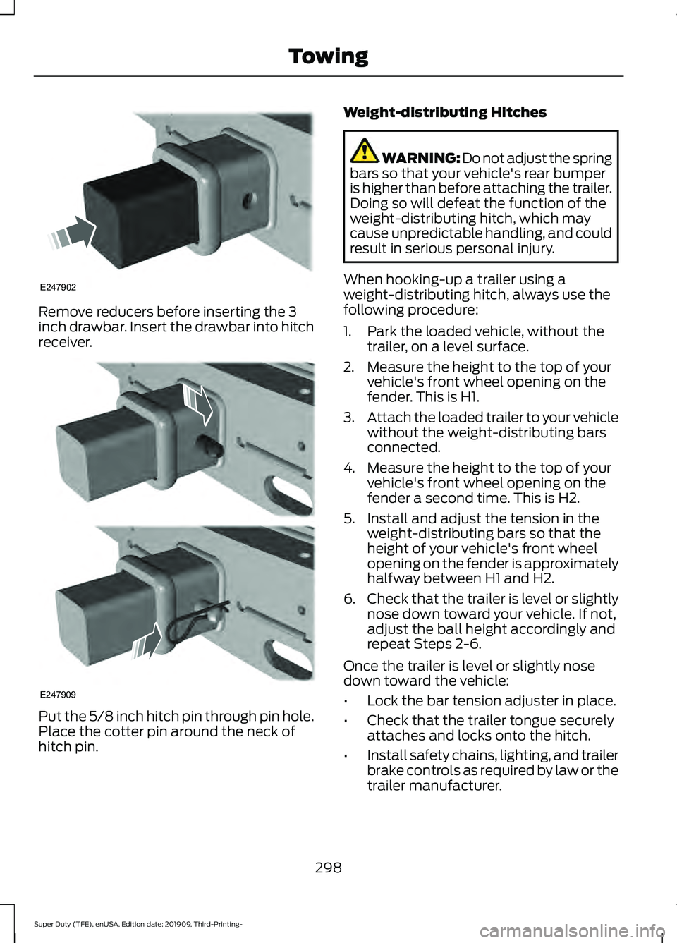
Remove reducers before inserting the 3
inch drawbar. Insert the drawbar into hitch
receiver.
Put the 5/8 inch hitch pin through pin hole.
Place the cotter pin around the neck of
hitch pin. Weight-distributing Hitches WARNING: Do not adjust the spring
bars so that your vehicle's rear bumper
is higher than before attaching the trailer.
Doing so will defeat the function of the
weight-distributing hitch, which may
cause unpredictable handling, and could
result in serious personal injury.
When hooking-up a trailer using a
weight-distributing hitch, always use the
following procedure:
1. Park the loaded vehicle, without the trailer, on a level surface.
2. Measure the height to the top of your vehicle's front wheel opening on the
fender. This is H1.
3. Attach the loaded trailer to your vehicle
without the weight-distributing bars
connected.
4. Measure the height to the top of your vehicle's front wheel opening on the
fender a second time. This is H2.
5. Install and adjust the tension in the weight-distributing bars so that the
height of your vehicle's front wheel
opening on the fender is approximately
halfway between H1 and H2.
6. Check that the trailer is level or slightly
nose down toward your vehicle. If not,
adjust the ball height accordingly and
repeat Steps 2-6.
Once the trailer is level or slightly nose
down toward the vehicle:
• Lock the bar tension adjuster in place.
• Check that the trailer tongue securely
attaches and locks onto the hitch.
• Install safety chains, lighting, and trailer
brake controls as required by law or the
trailer manufacturer.
298
Super Duty (TFE), enUSA, Edition date: 201909, Third-Printing- TowingE247902 E247909
Page 315 of 631
•
The tire air pressures recommended
for general driving are on the vehicle ’s
Safety Certification Label. The
maximum cold inflation pressure for
the tire and associated load rating is
on the tire sidewall. Tire air pressure
may require re-adjustment within these
pressure limits to accommodate the
additional weight of the snowplow
installation.
• Federal and some local regulations
require additional exterior lamps for
snowplow-equipped vehicles. Consult
your authorized dealer for additional
information.
Operating the Vehicle with the
Snowplow Attached
Note: Do not use your vehicle for snow
removal until you have driven at least
500 mi (800 km).
Ford recommends vehicle speed does not
exceed
45 mph (72 km/h) when
snowplowing.
If transporting a snowplow in summertime,
cooling system airflow may be blocked by
the snowplow. Change the snowplow
height or position to improve airflow to the
radiator or limit your vehicle speed to a
maximum of
45 mph (72 km/h).
The attached snowplow blade restricts
airflow to the radiator, and may cause the
engine to run at a higher temperature:
Attention to engine temperature is
especially important when outside
temperatures are above freezing. Angle
the blade to maximize airflow to the
radiator and monitor engine temperature
to determine whether a left or right angle
provides the best performance.
Follow the severe duty schedule in your
Scheduled Maintenance information for
engine oil and transmission fluid change
intervals. Snowplowing with your Airbag
Equipped Vehicle WARNING:
Do not attempt to
service, repair, or modify the
supplementary restraint system or
associated components. Failure to
follow this instruction could result in
personal injury or death. WARNING:
All occupants of your
vehicle, including the driver, should
always properly wear their seatbelts,
even when an airbag supplemental
restraint system is provided. Failure to
properly wear your seatbelt could
seriously increase the risk of injury or
death. WARNING:
Modifying or adding
equipment to the front end of your
vehicle (including hood, bumper system,
frame, front end body structure, tow
hooks and hood pins) may affect the
performance of the airbag system,
increasing the risk of injury. Do not
modify or add equipment to the front
end of your vehicle.
Note: Please refer to the Body Builders
Layout Book for instructions about the
appropriate installation of additional
equipment.
Your vehicle is equipped with a driver and
passenger airbag supplemental restraint
system. The supplemental restraint system
will activate in certain frontal and offset
frontal collisions when the vehicle sustains
sufficient frontal deceleration.
Careless or high speed driving while
plowing snow that results in sufficient
vehicle decelerations can deploy the
airbags. Such driving also increases the risk
of accidents.
312
Super Duty (TFE), enUSA, Edition date: 201909, Third-Printing- Driving Hints
Page 373 of 631
ADJUSTING THE HEADLAMPS
Vertical Aim Adjustment
The headlamps on your vehicle are
properly aimed at the assembly plant. If
your vehicle has been in an accident, the
alignment of your headlamps should be
checked by your authorized dealer.
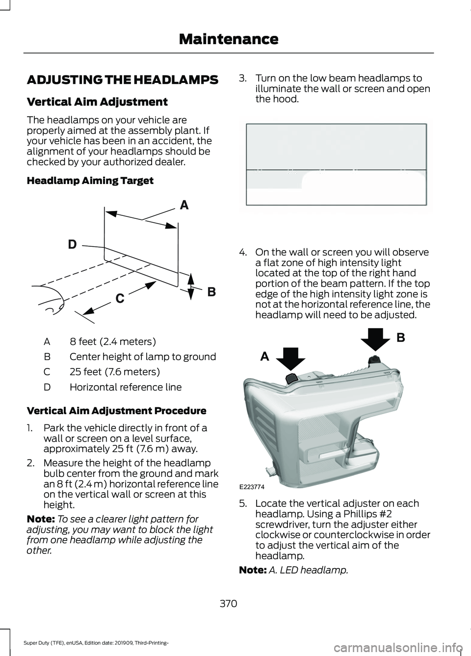
Headlamp Aiming Target
8 feet (2.4 meters)
A
Center height of lamp to ground
B
25 feet (7.6 meters)
C
Horizontal reference line
D
Vertical Aim Adjustment Procedure
1. Park the vehicle directly in front of a wall or screen on a level surface,
approximately 25 ft (7.6 m) away.
2. Measure the height of the headlamp bulb center from the ground and mark
an
8 ft (2.4 m) horizontal reference line
on the vertical wall or screen at this
height.
Note: To see a clearer light pattern for
adjusting, you may want to block the light
from one headlamp while adjusting the
other. 3. Turn on the low beam headlamps to
illuminate the wall or screen and open
the hood. 4. On the wall or screen you will observe
a flat zone of high intensity light
located at the top of the right hand
portion of the beam pattern. If the top
edge of the high intensity light zone is
not at the horizontal reference line, the
headlamp will need to be adjusted. 5. Locate the vertical adjuster on each
headlamp. Using a Phillips #2
screwdriver, turn the adjuster either
clockwise or counterclockwise in order
to adjust the vertical aim of the
headlamp.
Note: A. LED headlamp.
370
Super Duty (TFE), enUSA, Edition date: 201909, Third-Printing- MaintenanceE142592 E142465 A
B
E223774
Page 382 of 631
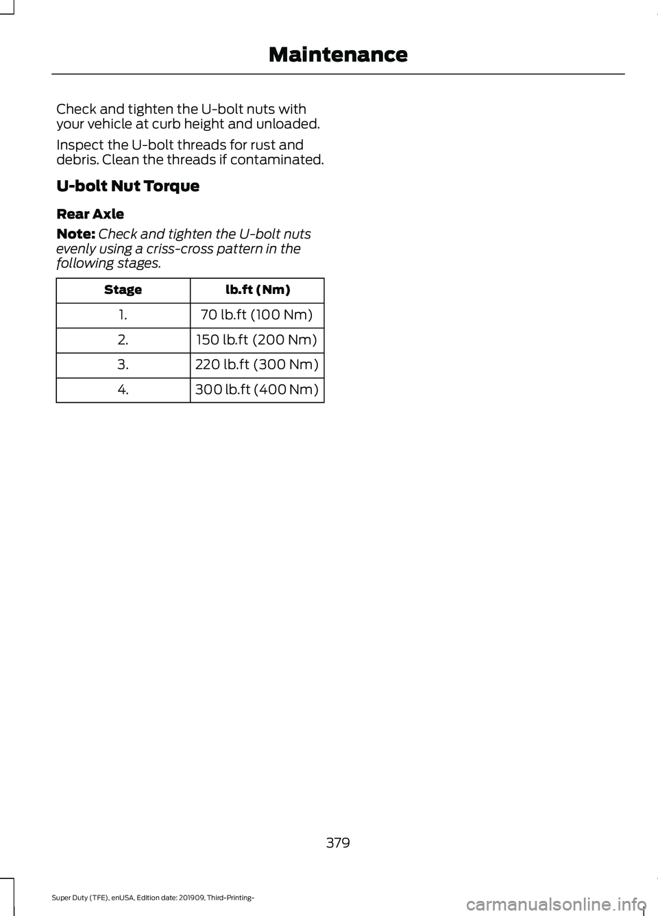
Check and tighten the U-bolt nuts with
your vehicle at curb height and unloaded.
Inspect the U-bolt threads for rust and
debris. Clean the threads if contaminated.
U-bolt Nut Torque
Rear Axle
Note:
Check and tighten the U-bolt nuts
evenly using a criss-cross pattern in the
following stages. lb.ft (Nm)
Stage
70 lb.ft (100 Nm)
1.
150 lb.ft (200 Nm)
2.
220 lb.ft (300 Nm)
3.
300 lb.ft (400 Nm)
4.
379
Super Duty (TFE), enUSA, Edition date: 201909, Third-Printing- Maintenance
Page 398 of 631
A.
P: Indicates a tire, designated
by the Tire and Rim Association,
that may be used for service on
cars, sport utility vehicles,
minivans and light trucks. Note:
If
your tire size does not begin with
a letter this may mean it is
designated by either the European
Tire and Rim Technical
Organization or the Japan Tire
Manufacturing Association.
B. 215:
Indicates the nominal
width of the tire in millimeters
from sidewall edge to sidewall
edge. In general, the larger the
number, the wider the tire.
C. 65:
Indicates the aspect ratio
which gives the tire's ratio of
height to width.
D. R:
Indicates a radial type tire.
E. 15:
Indicates the wheel or rim
diameter in inches. If you change
your wheel size, you will have to
purchase new tires to match the
new wheel diameter.
F. 95:
Indicates the tire's load
index. It is an index that relates to
how much weight a tire can carry.
You may find this information in
your owner ’s manual. If not,
contact a local tire dealer.
Note: You may not find this
information on all tires because it
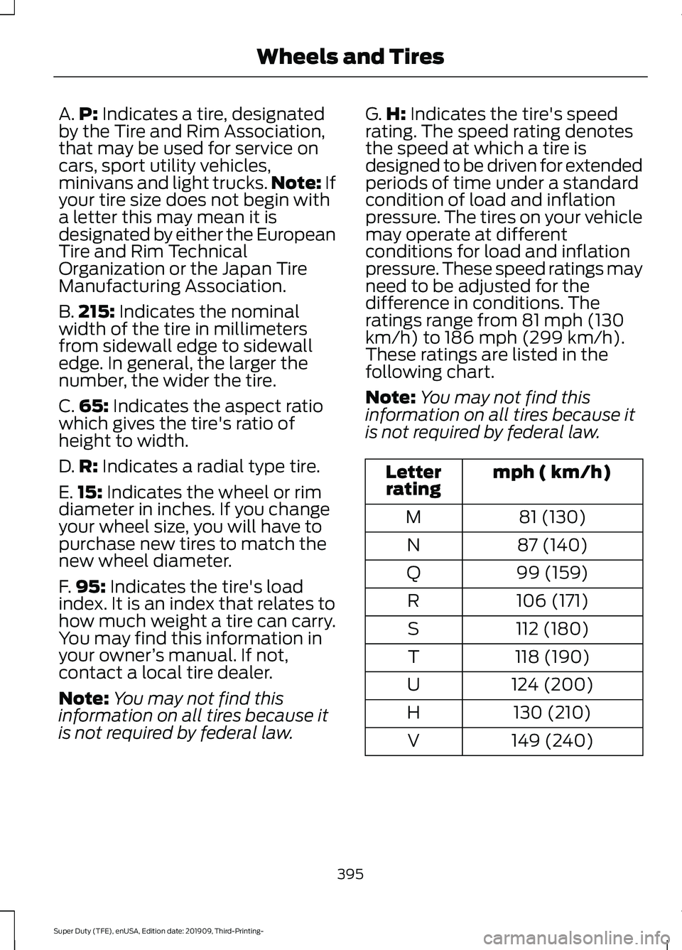
is not required by federal law. G.
H:
Indicates the tire's speed
rating. The speed rating denotes
the speed at which a tire is
designed to be driven for extended
periods of time under a standard
condition of load and inflation
pressure. The tires on your vehicle
may operate at different
conditions for load and inflation
pressure. These speed ratings may
need to be adjusted for the
difference in conditions. The
ratings range from 81 mph (130
km/h) to 186 mph (299 km/h).
These ratings are listed in the
following chart.
Note: You may not find this
information on all tires because it
is not required by federal law. mph ( km/h)
Letter
rating
81 (130)
M
87 (140)
N
99 (159)
Q
106 (171)
R
112 (180)
S
118 (190)
T
124 (200)
U
130 (210)
H
149 (240)
V
395
Super Duty (TFE), enUSA, Edition date: 201909, Third-Printing- Wheels and Tires
Page 401 of 631
D.
Maximum Load Single lb
(kg) at psi (kPa) cold: Indicates
the maximum load and tire
pressure when the tire is used as
a single; defined as two tires
(total) on the rear axle.
Information on T Type Tires
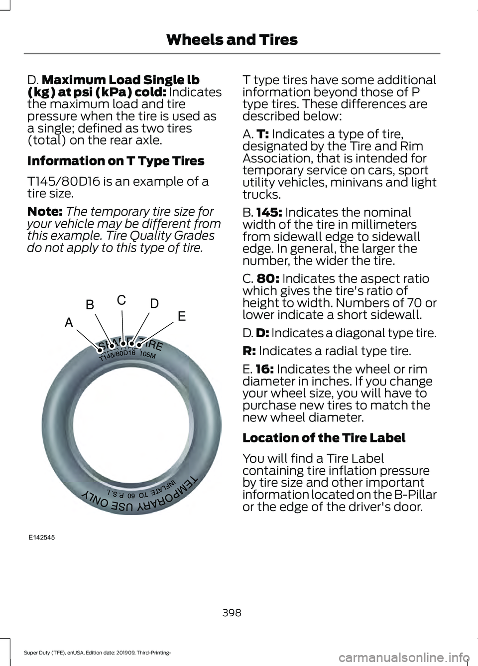
T145/80D16 is an example of a
tire size.
Note: The temporary tire size for
your vehicle may be different from
this example. Tire Quality Grades
do not apply to this type of tire. T type tires have some additional
information beyond those of P
type tires. These differences are
described below:
A.
T:
Indicates a type of tire,
designated by the Tire and Rim
Association, that is intended for
temporary service on cars, sport
utility vehicles, minivans and light
trucks.
B. 145:
Indicates the nominal
width of the tire in millimeters
from sidewall edge to sidewall
edge. In general, the larger the
number, the wider the tire.
C. 80:
Indicates the aspect ratio
which gives the tire's ratio of
height to width. Numbers of 70 or
lower indicate a short sidewall.
D. D:
Indicates a diagonal type tire.
R:
Indicates a radial type tire.
E. 16:
Indicates the wheel or rim
diameter in inches. If you change
your wheel size, you will have to
purchase new tires to match the
new wheel diameter.
Location of the Tire Label
You will find a Tire Label
containing tire inflation pressure
by tire size and other important
information located on the B-Pillar
or the edge of the driver's door.
398
Super Duty (TFE), enUSA, Edition date: 201909, Third-Printing- Wheels and TiresA
BCDE
E142545
Page 406 of 631
it needs to be repaired or replaced.
For your safety, tires that are
damaged or show signs of
excessive wear should not be used
because they are more likely to
blow out or fail.
Improper or inadequate vehicle
maintenance can cause tires to
wear abnormally. Inspect all your
tires, including the spare,
frequently, and replace them if
one or more of the following
conditions exist:
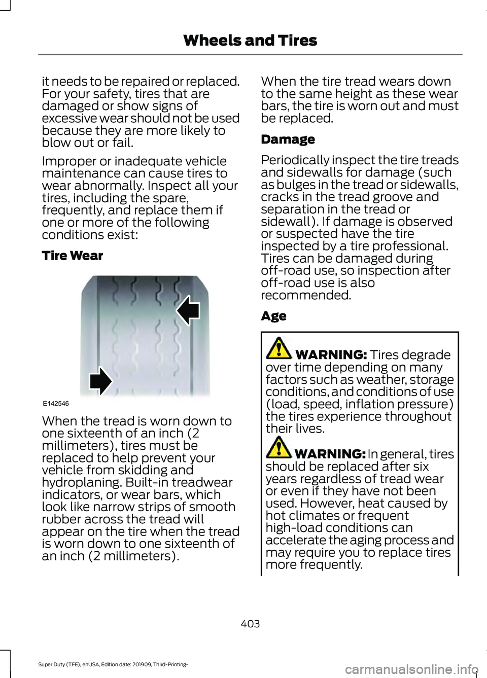
Tire Wear
When the tread is worn down to
one sixteenth of an inch (2
millimeters), tires must be
replaced to help prevent your
vehicle from skidding and
hydroplaning. Built-in treadwear
indicators, or wear bars, which
look like narrow strips of smooth
rubber across the tread will
appear on the tire when the tread
is worn down to one sixteenth of
an inch (2 millimeters). When the tire tread wears down
to the same height as these wear
bars, the tire is worn out and must
be replaced.
Damage
Periodically inspect the tire treads
and sidewalls for damage (such
as bulges in the tread or sidewalls,
cracks in the tread groove and
separation in the tread or
sidewall). If damage is observed
or suspected have the tire
inspected by a tire professional.
Tires can be damaged during
off-road use, so inspection after
off-road use is also
recommended.
Age
WARNING: Tires degrade
over time depending on many
factors such as weather, storage
conditions, and conditions of use
(load, speed, inflation pressure)
the tires experience throughout
their lives. WARNING: In general, tires
should be replaced after six
years regardless of tread wear
or even if they have not been
used. However, heat caused by
hot climates or frequent
high-load conditions can
accelerate the aging process and
may require you to replace tires
more frequently.
403
Super Duty (TFE), enUSA, Edition date: 201909, Third-Printing- Wheels and TiresE142546
Page 627 of 631
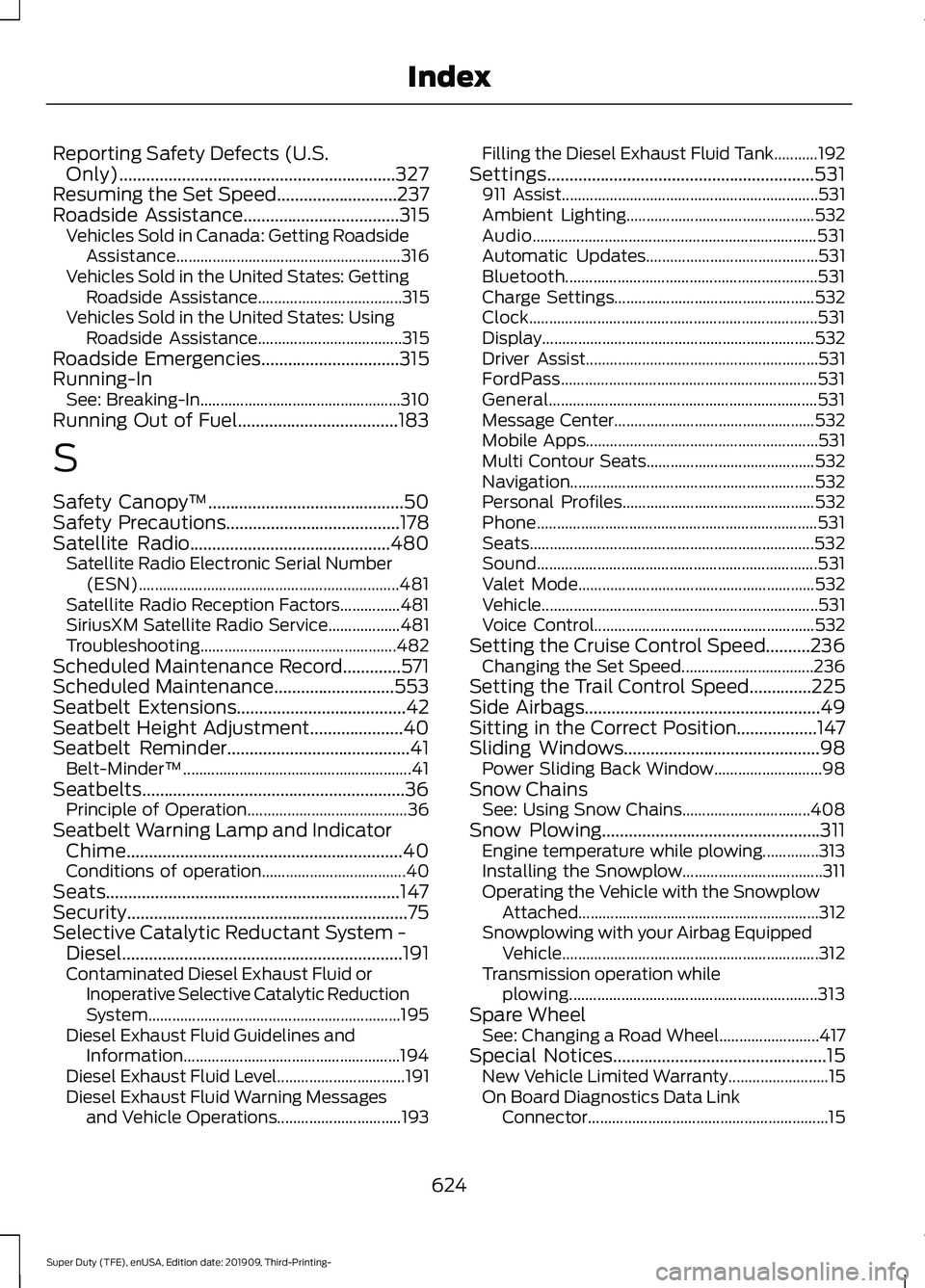
Reporting Safety Defects (U.S.
Only)..............................................................327
Resuming the Set Speed...........................237
Roadside Assistance...................................315
Vehicles Sold in Canada: Getting Roadside
Assistance........................................................ 316
Vehicles Sold in the United States: Getting Roadside Assistance.................................... 315
Vehicles Sold in the United States: Using Roadside Assistance.................................... 315
Roadside Emergencies
...............................315
Running-In See: Breaking-In.................................................. 310
Running Out of Fuel....................................183
S
Safety Canopy ™
............................................50
Safety Precautions.......................................178
Satellite Radio.............................................480
Satellite Radio Electronic Serial Number
(ESN)................................................................. 481
Satellite Radio Reception Factors...............481
SiriusXM Satellite Radio Service.................. 481
Troubleshooting................................................. 482
Scheduled Maintenance Record.............571
Scheduled Maintenance
...........................553
Seatbelt Extensions......................................42
Seatbelt Height Adjustment.....................40
Seatbelt Reminder.........................................41 Belt-Minder™......................................................... 41
Seatbelts...........................................................36 Principle of Operation........................................ 36
Seatbelt Warning Lamp and Indicator Chime..............................................................40
Conditions of operation.................................... 40
Seats..................................................................147
Security...............................................................75
Selective Catalytic Reductant System - Diesel...............................................................191
Contaminated Diesel Exhaust Fluid or Inoperative Selective Catalytic Reduction
System............................................................... 195
Diesel Exhaust Fluid Guidelines and Information...................................................... 194
Diesel Exhaust Fluid Level................................ 191
Diesel Exhaust Fluid Warning Messages and Vehicle Operations............................... 193Filling the Diesel Exhaust Fluid Tank...........192
Settings............................................................531 911 Assist................................................................ 531
Ambient Lighting............................................... 532
Audio....................................................................... 531
Automatic Updates........................................... 531
Bluetooth............................................................... 531
Charge Settings.................................................. 532
Clock........................................................................\
531
Display.................................................................... 532
Driver Assist.......................................................... 531
FordPass................................................................ 531
General................................................................... 531
Message Center.................................................. 532
Mobile Apps.......................................................... 531
Multi Contour Seats.......................................... 532
Navigation............................................................. 532
Personal Profiles................................................ 532
Phone...................................................................... 531
Seats....................................................................... 532
Sound...................................................................... 531
Valet Mode........................................................... 532
Vehicle..................................................................... 531
Voice Control....................................................... 532
Setting the Cruise Control Speed..........236 Changing the Set Speed................................. 236
Setting the Trail Control Speed..............225
Side Airbags.....................................................49
Sitting in the Correct Position..................147
Sliding Windows
............................................98
Power Sliding Back Window........................... 98
Snow Chains See: Using Snow Chains................................ 408
Snow Plowing.................................................311 Engine temperature while plowing..............313
Installing the Snowplow................................... 311
Operating the Vehicle with the Snowplow Attached............................................................ 312
Snowplowing with your Airbag Equipped Vehicle................................................................ 312
Transmission operation while plowing.............................................................. 313
Spare Wheel See: Changing a Road Wheel......................... 417
Special Notices
................................................15
New Vehicle Limited Warranty......................... 15
On Board Diagnostics Data Link Connector............................................................ 15
624
Super Duty (TFE), enUSA, Edition date: 201909, Third-Printing- Index