ECU FORD F-450 2020 Owner's Manual
[x] Cancel search | Manufacturer: FORD, Model Year: 2020, Model line: F-450, Model: FORD F-450 2020Pages: 631, PDF Size: 9.62 MB
Page 76 of 631
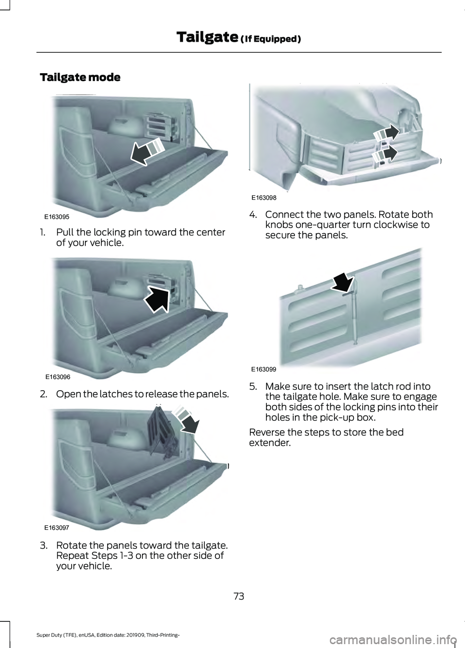
Tailgate mode
1. Pull the locking pin toward the center
of your vehicle. 2.
Open the latches to release the panels. 3. Rotate the panels toward the tailgate.
Repeat Steps 1-3 on the other side of
your vehicle. 4. Connect the two panels. Rotate both
knobs one-quarter turn clockwise to
secure the panels. 5. Make sure to insert the latch rod into
the tailgate hole. Make sure to engage
both sides of the locking pins into their
holes in the pick-up box.
Reverse the steps to store the bed
extender.
73
Super Duty (TFE), enUSA, Edition date: 201909, Third-Printing- Tailgate (If Equipped)E163095 E163096 E163097 E163098 E163099
Page 78 of 631
PASSIVE ANTI-THEFT
SYSTEM
The system prevents someone from
starting the engine with an incorrectly
coded key.
Note:
The system is not compatible with
aftermarket remote start systems. Use of
these may result in engine starting problems
and a loss of security.
Note: Metallic objects, electronic devices
or a second coded key on the same key
chain could cause vehicle starting problems
if they are too close to the key when starting
the engine. Prevent these objects from
touching the coded key when starting the
engine. Switch the ignition off, move all
objects on the key chain away from the
coded key and restart the engine if a
problem occurs.
Note: Do not leave a duplicate coded key
in your vehicle. Always take your keys and
lock all doors when leaving your vehicle.
SecuriLock®
The system helps prevent the engine from
starting unless you use a coded key
programmed to your vehicle. Using the
wrong key may prevent your vehicle from
starting.
A message could appear in the information
display.
If you are unable to start your vehicle with
a coded key, it is not operating correctly.
A message could appear in the information
display.
Automatic Arming
The system arms when you switch the
ignition off. Automatic Disarming
The system disarms when you switch the
ignition on with a coded key.
ANTI-THEFT ALARM
The active anti-theft system is designed
to warn you in the event of unauthorized
vehicle entry and is also designed to help
prevent unwanted towing of your vehicle.
You can choose what is monitored by
arming the system in different ways. See
Information Displays (page 109).
The direction indicators flash and the horn
sounds if the system triggers while the
alarm is armed.
Take all remote controls to an authorized
dealer if there is any potential alarm
problem with your vehicle.
Using the System
You can select two levels of alarm security.
You can change the level of security when
the ignition is switched off through the
information display with the two options
below:
Perimeter Only (If Equipped)
Perimeter only monitors the following:
• Doors.
• Hood.
• Tailgate.
All Sensors (If Equipped)
All sensors monitors the following:
• Doors.
• Hood.
• Tailgate.
• Movement inside your vehicle.
• Change in vehicle inclination, for
example, unwanted towing.
75
Super Duty (TFE), enUSA, Edition date: 201909, Third-Printing- Security
Page 79 of 631
Note:
Do not choose all sensors monitor
mode when the vehicle is in transport or if
movement within the vehicle is likely to
occur.
Note: For correct operation of the interior
motion detection system, make sure you
close all the windows prior to arming the
system. This helps prevent accidental alarm
activation due to external influences.
Additionally, the interior motion sensing
system does not arm if any door is ajar.
Arming the Alarm
The alarm is ready to arm when there is
not a key in the ignition. Lock your vehicle
using the remote control or keyless entry
keypad. You can also lock your vehicle
using the lock sensor on the exterior door
handle if your vehicle is equipped with
intelligent access. See Locking and
Unlocking (page 65).
The direction indicators flash once after
you lock your vehicle. This indicates the
alarm is in the pre-armed mode. It fully
arms after 20 seconds.
Disarming the Alarm
Disarm the alarm by any of the following
actions:
• Press the power door unlock button
within the 20-second pre-armed mode.
• Unlock the doors with the remote
control or keyless entry keypad. If
equipped with intelligent access, you
can use the unlock sensor on the
exterior door handle. See
Locking and
Unlocking (page 65).
• Switch the ignition on or start your
vehicle.
• Use a key in the driver door lock
cylinder to unlock your vehicle, then
switch the ignition on within 12
seconds.
76
Super Duty (TFE), enUSA, Edition date: 201909, Third-Printing- Security
Page 126 of 631
Airbag
Action
Message
Displays when the system detects a malfunction due to a blocked sensor.
Occupant Sensor
BLOCKED Remove
Objects Near Passenger Seat
Alarm and Security Action
Message
Alarm triggered due to unauthorized entry. See Anti-Theft
Alarm (page 75).
Vehicle Alarm To Stop
Alarm, Start Vehicle.
Automatic Engine Shutdown Action
Message
The engine is getting ready to shut off.
Engine Shuts Off In
{seconds to shut off:#0} Seconds
The engine has shut off to help increase fuel economy.
Engine Shut Off For Fuel
Economy
The engine is getting ready to shut off. Follow the promptfrom the message to override the shut down.
Engine Shuts Off in
{seconds to shut off:#0} Seconds Press Ok to Override
123
Super Duty (TFE), enUSA, Edition date: 201909, Third-Printing- Information Displays
Page 161 of 631
UNIVERSAL GARAGE DOOR
OPENER
HomeLink Wireless Control
System
WARNING: Do not use the system
with any garage door opener that does
not have the safety stop and reverse
feature as required by U.S. Federal
Safety Standards (this includes any
garage door opener manufactured
before April 1, 1982). A garage door
opener which cannot detect an object,
signaling the door to stop and reverse,
does not meet current federal safety
standards. Using a garage door opener
without these features increases the risk
of serious injury or death.
Note: Make sure that the garage door and
security device are free from obstruction
when you are programming. Do not program
the system with the vehicle in the garage.
Note: Make sure you keep the original
remote control transmitter for use in other
vehicles as well as for future system
programming.
Note: We recommend that upon the sale
or lease termination of your vehicle, you
erase the programmed function buttons for
security reasons. See Erasing the Function
Button Codes
later in this section.
Note: You can program a maximum of
three devices. To change or replace any of
the three devices after it has been initially
programmed, you must first erase the
current settings. See Erasing the Function
Button Codes
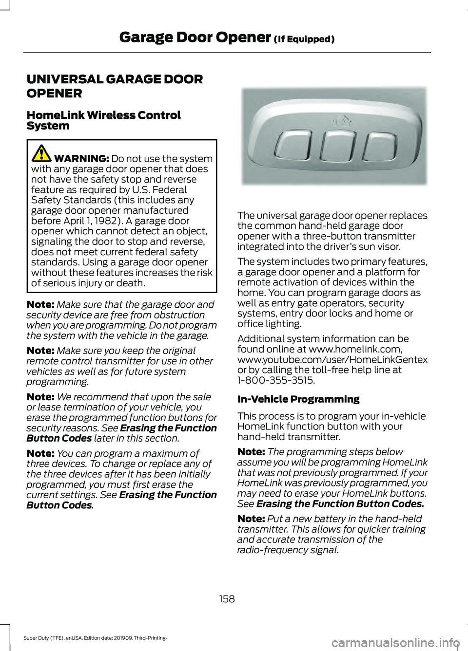
. The universal garage door opener replaces
the common hand-held garage door
opener with a three-button transmitter
integrated into the driver
’s sun visor.
The system includes two primary features,
a garage door opener and a platform for
remote activation of devices within the
home. You can program garage doors as
well as entry gate operators, security
systems, entry door locks and home or
office lighting.
Additional system information can be
found online at www.homelink.com,
www.youtube.com/user/HomeLinkGentex
or by calling the toll-free help line at
1-800-355-3515.
In-Vehicle Programming
This process is to program your in-vehicle
HomeLink function button with your
hand-held transmitter.
Note: The programming steps below
assume you will be programming HomeLink
that was not previously programmed. If your
HomeLink was previously programmed, you
may need to erase your HomeLink buttons.
See Erasing the Function Button Codes.
Note: Put a new battery in the hand-held
transmitter. This allows for quicker training
and accurate transmission of the
radio-frequency signal.
158
Super Duty (TFE), enUSA, Edition date: 201909, Third-Printing- Garage Door Opener
(If Equipped)E188211
Page 204 of 631
AUTOMATIC TRANSMISSION
WARNING: Apply the parking
brake, shift into park (P), switch the
ignition off and remove the key before
you leave your vehicle. Failure to follow
this instruction could result in personal
injury or death. WARNING:
When your vehicle is
stationary, keep the brake pedal fully
pressed when shifting gears. Failure to
follow this instruction could result in
personal injury, death or property
damage.
Note: You may not be able to shift out of
park (P) unless the intelligent access key is
inside your vehicle.
Understanding the Shift Positions
of Your Automatic Transmission
(If Equipped)
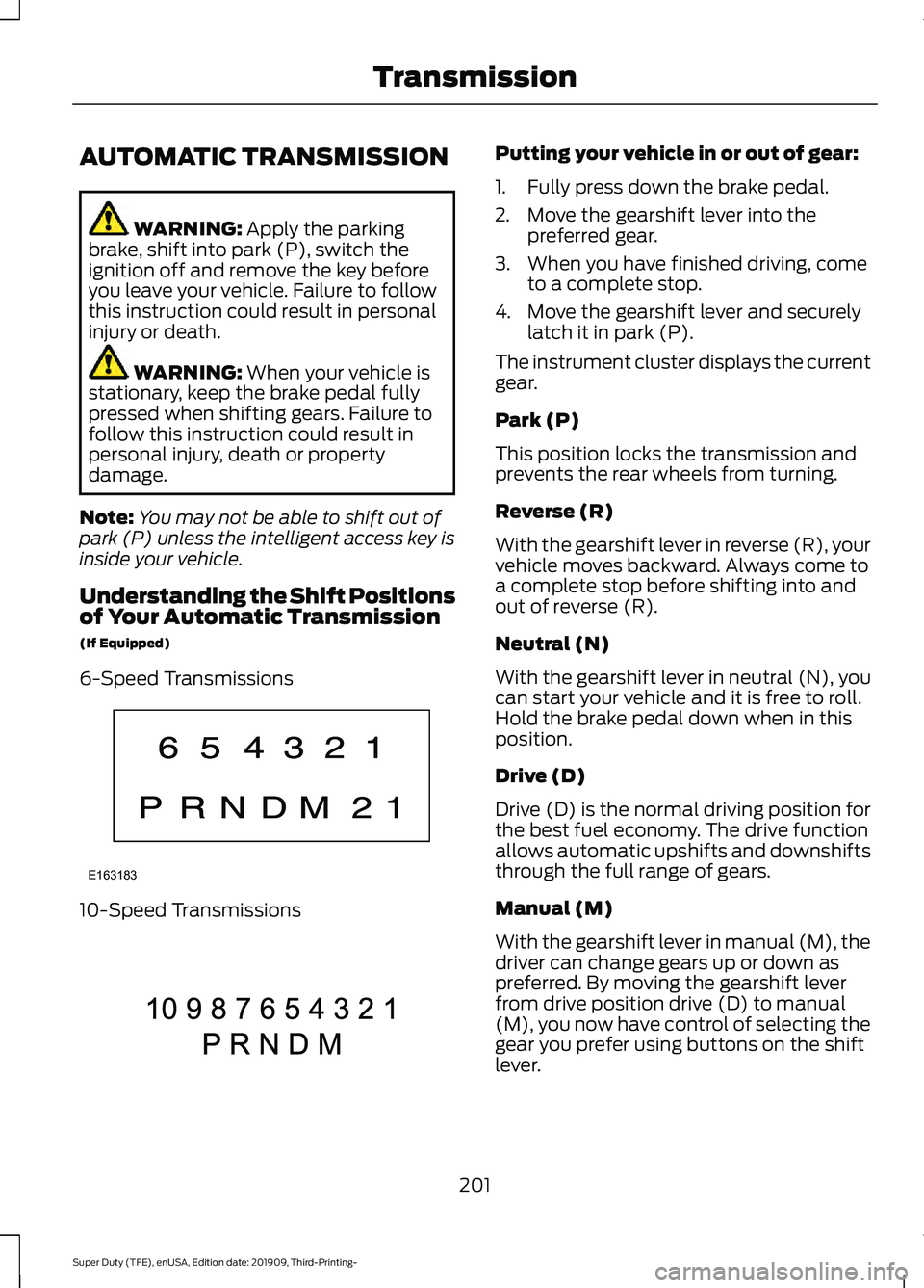
6-Speed Transmissions 10-Speed Transmissions Putting your vehicle in or out of gear:
1. Fully press down the brake pedal.
2. Move the gearshift lever into the
preferred gear.
3. When you have finished driving, come to a complete stop.
4. Move the gearshift lever and securely latch it in park (P).
The instrument cluster displays the current
gear.
Park (P)
This position locks the transmission and
prevents the rear wheels from turning.
Reverse (R)
With the gearshift lever in reverse (R), your
vehicle moves backward. Always come to
a complete stop before shifting into and
out of reverse (R).
Neutral (N)
With the gearshift lever in neutral (N), you
can start your vehicle and it is free to roll.
Hold the brake pedal down when in this
position.
Drive (D)
Drive (D) is the normal driving position for
the best fuel economy. The drive function
allows automatic upshifts and downshifts
through the full range of gears.
Manual (M)
With the gearshift lever in manual (M), the
driver can change gears up or down as
preferred. By moving the gearshift lever
from drive position drive (D) to manual
(M), you now have control of selecting the
gear you prefer using buttons on the shift
lever.
201
Super Duty (TFE), enUSA, Edition date: 201909, Third-Printing- TransmissionE163183 E308145
Page 208 of 631
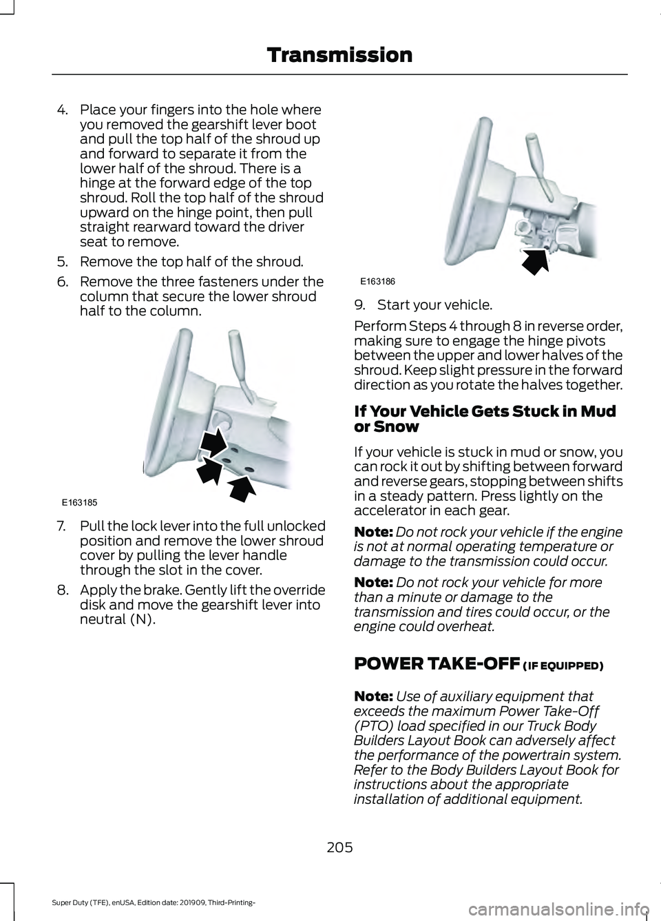
4. Place your fingers into the hole where
you removed the gearshift lever boot
and pull the top half of the shroud up
and forward to separate it from the
lower half of the shroud. There is a
hinge at the forward edge of the top
shroud. Roll the top half of the shroud
upward on the hinge point, then pull
straight rearward toward the driver
seat to remove.
5. Remove the top half of the shroud.
6. Remove the three fasteners under the column that secure the lower shroud
half to the column. 7.
Pull the lock lever into the full unlocked
position and remove the lower shroud
cover by pulling the lever handle
through the slot in the cover.
8. Apply the brake. Gently lift the override
disk and move the gearshift lever into
neutral (N). 9. Start your vehicle.
Perform Steps 4 through 8 in reverse order,
making sure to engage the hinge pivots
between the upper and lower halves of the
shroud. Keep slight pressure in the forward
direction as you rotate the halves together.
If Your Vehicle Gets Stuck in Mud
or Snow
If your vehicle is stuck in mud or snow, you
can rock it out by shifting between forward
and reverse gears, stopping between shifts
in a steady pattern. Press lightly on the
accelerator in each gear.
Note:
Do not rock your vehicle if the engine
is not at normal operating temperature or
damage to the transmission could occur.
Note: Do not rock your vehicle for more
than a minute or damage to the
transmission and tires could occur, or the
engine could overheat.
POWER TAKE-OFF (IF EQUIPPED)
Note: Use of auxiliary equipment that
exceeds the maximum Power Take-Off
(PTO) load specified in our Truck Body
Builders Layout Book can adversely affect
the performance of the powertrain system.
Refer to the Body Builders Layout Book for
instructions about the appropriate
installation of additional equipment.
205
Super Duty (TFE), enUSA, Edition date: 201909, Third-Printing- TransmissionE163185 E163186
Page 274 of 631
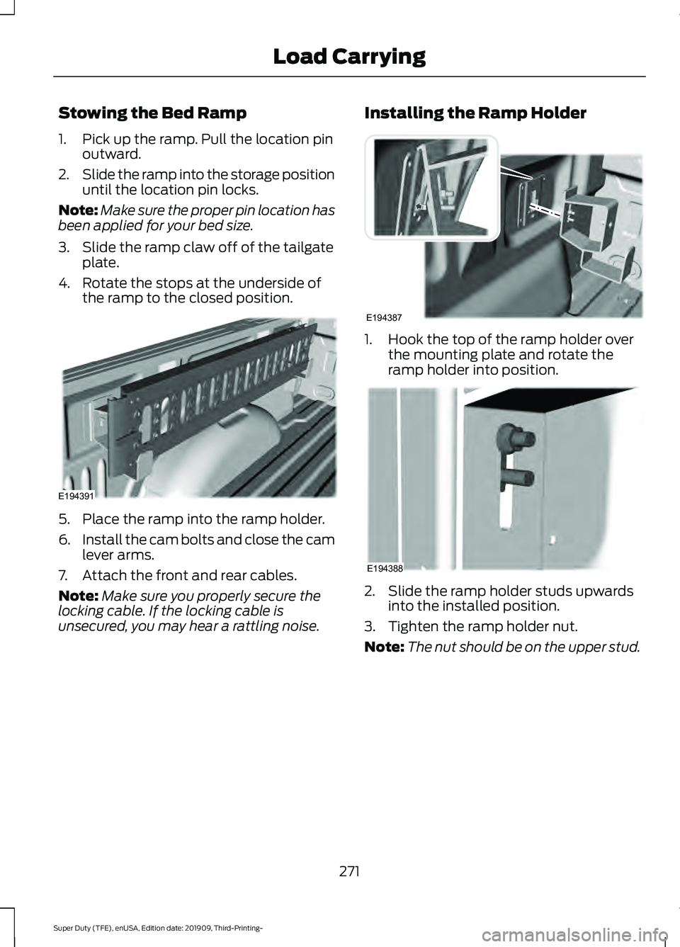
Stowing the Bed Ramp
1. Pick up the ramp. Pull the location pin
outward.
2. Slide the ramp into the storage position
until the location pin locks.
Note: Make sure the proper pin location has
been applied for your bed size.
3. Slide the ramp claw off of the tailgate plate.
4. Rotate the stops at the underside of the ramp to the closed position. 5. Place the ramp into the ramp holder.
6.
Install the cam bolts and close the cam
lever arms.
7. Attach the front and rear cables.
Note: Make sure you properly secure the
locking cable. If the locking cable is
unsecured, you may hear a rattling noise. Installing the Ramp Holder 1. Hook the top of the ramp holder over
the mounting plate and rotate the
ramp holder into position. 2. Slide the ramp holder studs upwards
into the installed position.
3. Tighten the ramp holder nut.
Note: The nut should be on the upper stud.
271
Super Duty (TFE), enUSA, Edition date: 201909, Third-Printing- Load CarryingE194391 E194387 E194388
Page 290 of 631
Troubleshooting - Fifth Wheel and
Gooseneck Trailer
Setup
The system is designed to be used with a
wide variety of trailers. There are some
trailers that do not have a proper surface
and location to mount the sensor. These
trailers are not supported. Attempts to
install the sensor in a manner that does
not meet the requirements can result in
improper system function.
To correctly install the trailer sensor:
•
Attach to vertical surface with the
arrows pointed straight up.
• If you are not sure, use a level to check
that the attachment surface is vertical.
• Securely fasten the sensor so that it is
rigidly mounted and does not shake or
wobble.
• Install within the range of the 12 way
connector so that when the trailer
swings the wire harness does not
stretch, pinch or pull.
If the system displays Pro Trailer Backup
Assist™ Sensor Not Detected Refer to
Owner's Manual Press Knob to Exit or
Trailer Reverse Guidance Sensor Not
Detected Refer to Owner's Manual Press
OK to Exit:
• Check that the 12 way connector is fully
inserted into the 12 way socket. The red
rubber seal is not visible when the
connector is fully inserted.
• Check that the wiring harness sensor
connection is fully inserted at the trailer
sensor.
• Check for damaged wiring between the
12 way connector and the trailer sensor.
• If you have a 12 way connector inside
the bed and in the bumper, ensure that
only a single sensor is connected. Note:
If you did not purchase the fifth wheel
prep pack, you need to replace the 7/4 way
trailer connector in your bumper with a 7/12
pin connector. See your authorized dealer.
Calibration
The calibration process is required for the
system to determine the trailer length. The
system supports trailer lengths of 10– 39 ft
(3– 11.94 m) distance from the hitch point
to the center of the axle or axles. The
calibration process consists of a straight
forward drive followed by a turn. During
the straight drive, the system monitors
various vehicle parameters to make sure
your vehicle is being driven straight and the
trailer is straight behind your vehicle. Any
steering input or trailer movement during
this straight drive pauses the calibration.
During the turn, the system monitors
various vehicle parameters to make sure
your vehicle and trailer are correctly
turning.
For best results:
• Use a smooth and level road when
attempting to calibrate.
• Steer and smoothly turn and avoid
abrupt steering inputs.
• Drive between 2 –16 mph (4– 25 km/h)
.
• Make a typical 90 degree corner turn.
Turning too shallow does not allow the
system to calibrate.
The typical calibration process results in
the system displaying messages in the
information display. The system also
displays additional warnings if the vehicle
or trailer motion is not within the
calibration limits.
287
Super Duty (TFE), enUSA, Edition date: 201909, Third-Printing- Towing
Page 301 of 631
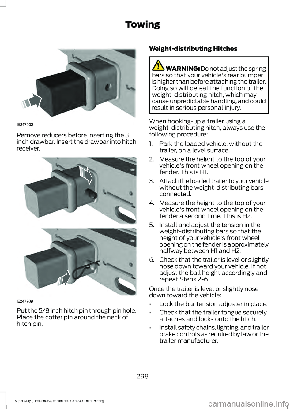
Remove reducers before inserting the 3
inch drawbar. Insert the drawbar into hitch
receiver.
Put the 5/8 inch hitch pin through pin hole.
Place the cotter pin around the neck of
hitch pin. Weight-distributing Hitches WARNING: Do not adjust the spring
bars so that your vehicle's rear bumper
is higher than before attaching the trailer.
Doing so will defeat the function of the
weight-distributing hitch, which may
cause unpredictable handling, and could
result in serious personal injury.
When hooking-up a trailer using a
weight-distributing hitch, always use the
following procedure:
1. Park the loaded vehicle, without the trailer, on a level surface.
2. Measure the height to the top of your vehicle's front wheel opening on the
fender. This is H1.
3. Attach the loaded trailer to your vehicle
without the weight-distributing bars
connected.
4. Measure the height to the top of your vehicle's front wheel opening on the
fender a second time. This is H2.
5. Install and adjust the tension in the weight-distributing bars so that the
height of your vehicle's front wheel
opening on the fender is approximately
halfway between H1 and H2.
6. Check that the trailer is level or slightly
nose down toward your vehicle. If not,
adjust the ball height accordingly and
repeat Steps 2-6.
Once the trailer is level or slightly nose
down toward the vehicle:
• Lock the bar tension adjuster in place.
• Check that the trailer tongue securely
attaches and locks onto the hitch.
• Install safety chains, lighting, and trailer
brake controls as required by law or the
trailer manufacturer.
298
Super Duty (TFE), enUSA, Edition date: 201909, Third-Printing- TowingE247902 E247909