relay FORD F-550 2020 Owners Manual
[x] Cancel search | Manufacturer: FORD, Model Year: 2020, Model line: F-550, Model: FORD F-550 2020Pages: 631, PDF Size: 9.62 MB
Page 275 of 631
TOWING A TRAILER
WARNING: Do not exceed
the GVWR or the GAWR
specified on the certification
label. WARNING:
Towing trailers
beyond the maximum
recommended gross trailer
weight exceeds the limit of your
vehicle and could result in engine
damage, transmission damage,
structural damage, loss of
vehicle control, vehicle rollover
and personal injury. WARNING:
Do not exceed
the lowest rating capacity for
your vehicle or trailer hitch.
Overloading your vehicle or
trailer hitch can impair your
vehicle stability and handling.
Failure to follow this instruction
could result in the loss of control
of your vehicle, personal injury or
death. WARNING:
Do not cut,
drill, weld or modify the trailer
hitch. Modifying the trailer hitch
could reduce the hitch rating. Note:
To prevent your trailer from
accumulating distance, and the
trailer information status appearing
when you restart your vehicle after
disconnecting your trailer, you must
deactivate your trailer. Using the
information display, go to the
Towing menu and then the Select
Trailer option. Select the No active
trailer option. See
Information
Displays (page 109).
Your vehicle may have electrical
items, such as fuses or relays,
related to towing. See
Fuses
(page 329).
Your vehicle may have ability to
modify trailer towing features.
See
General Information (page
109).
Your vehicle's load capacity
designation is by weight, not by
volume, so you cannot necessarily
use all available space when
loading a vehicle or trailer.
Towing a trailer places an extra
load on your vehicle's engine,
transmission, axle, brakes, tires
and suspension. Inspect these
components periodically during,
and after, any towing operation.
272
Super Duty (TFE), enUSA, Edition date: 201909, Third-Printing- Towing
Page 299 of 631
Note:
If your vehicle is equipped with a
factory brake controller, the Battery (+)
Orange wire is powered when you start the
engine and you apply the brakes at least
once when a trailer with brake lamps is
connected. If your vehicle is not equipped
with a factory brake controller, relays control
the system and it becomes active when you
power on your vehicle.
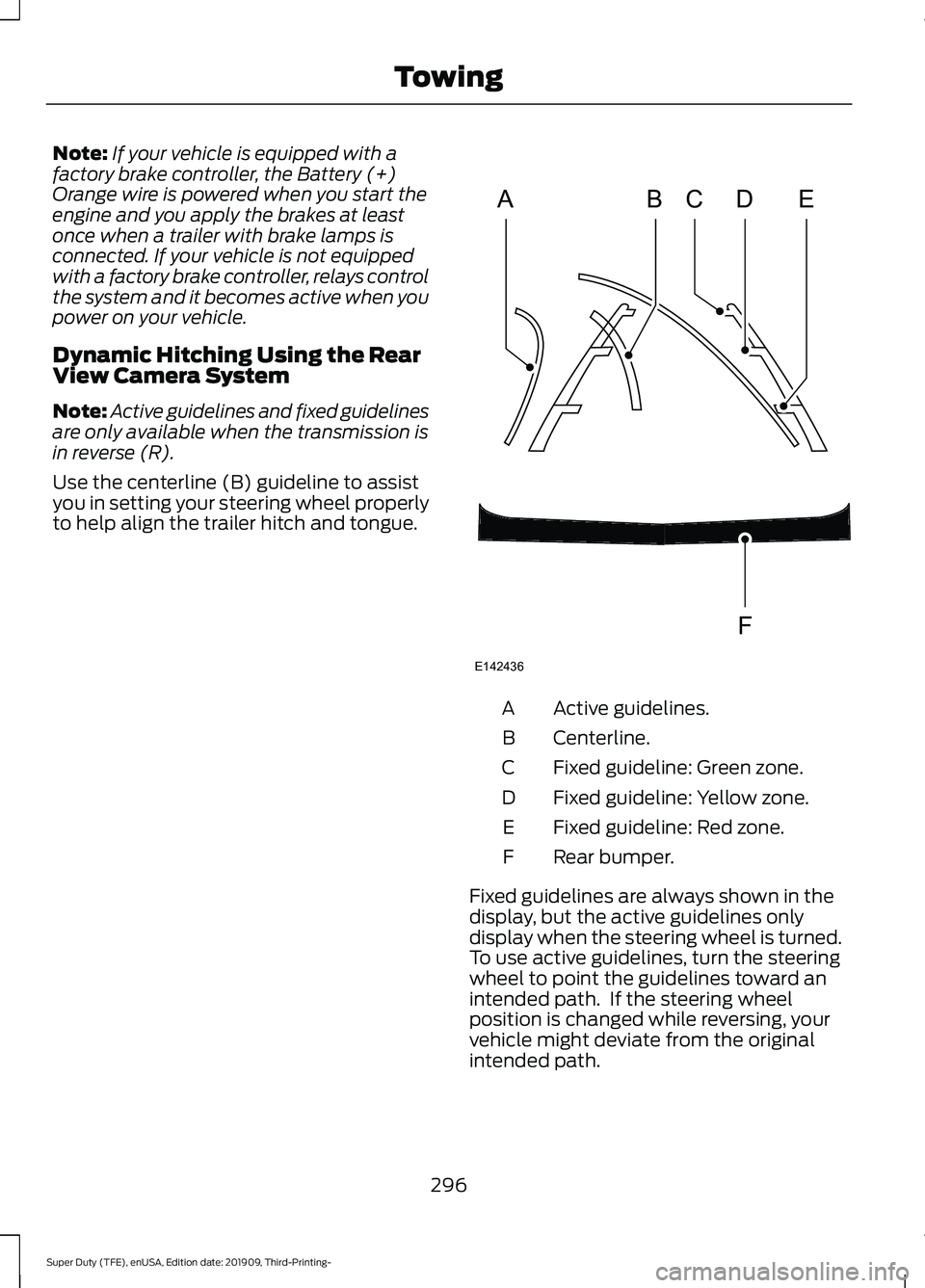
Dynamic Hitching Using the Rear
View Camera System
Note: Active guidelines and fixed guidelines
are only available when the transmission is
in reverse (R).
Use the centerline (B) guideline to assist
you in setting your steering wheel properly
to help align the trailer hitch and tongue. Active guidelines.
A
Centerline.
B
Fixed guideline: Green zone.
C
Fixed guideline: Yellow zone.
D
Fixed guideline: Red zone.
E
Rear bumper.
F
Fixed guidelines are always shown in the
display, but the active guidelines only
display when the steering wheel is turned.
To use active guidelines, turn the steering
wheel to point the guidelines toward an
intended path. If the steering wheel
position is changed while reversing, your
vehicle might deviate from the original
intended path.
296
Super Duty (TFE), enUSA, Edition date: 201909, Third-Printing- TowingABCD
F
E
E142436
Page 335 of 631
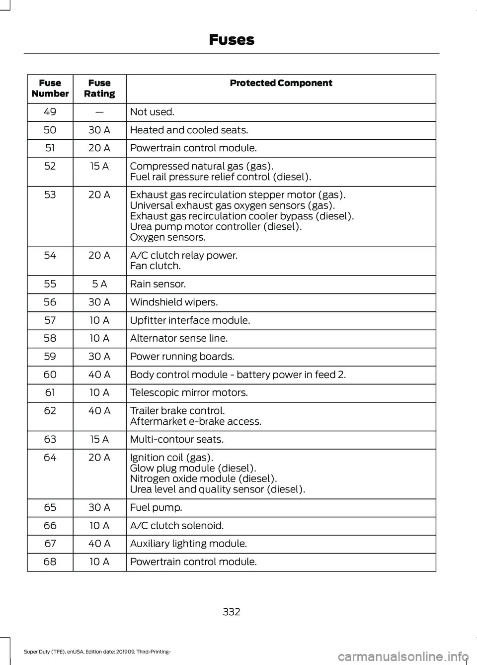
Protected Component
Fuse
Rating
Fuse
Number
Not used.
—
49
Heated and cooled seats.
30 A
50
Powertrain control module.
20 A
51
Compressed natural gas (gas).
15 A
52
Fuel rail pressure relief control (diesel).
Exhaust gas recirculation stepper motor (gas).
20 A
53
Universal exhaust gas oxygen sensors (gas).
Exhaust gas recirculation cooler bypass (diesel).
Urea pump motor controller (diesel).
Oxygen sensors.
A/C clutch relay power.
20 A
54
Fan clutch.
Rain sensor.
5 A
55
Windshield wipers.
30 A
56
Upfitter interface module.
10 A
57
Alternator sense line.
10 A
58
Power running boards.
30 A
59
Body control module - battery power in feed 2.
40 A
60
Telescopic mirror motors.
10 A
61
Trailer brake control.
40 A
62
Aftermarket e-brake access.
Multi-contour seats.
15 A
63
Ignition coil (gas).
20 A
64
Glow plug module (diesel).
Nitrogen oxide module (diesel).
Urea level and quality sensor (diesel).
Fuel pump.
30 A
65
A/C clutch solenoid.
10 A
66
Auxiliary lighting module.
40 A
67
Powertrain control module.
10 A
68
332
Super Duty (TFE), enUSA, Edition date: 201909, Third-Printing- Fuses
Page 338 of 631
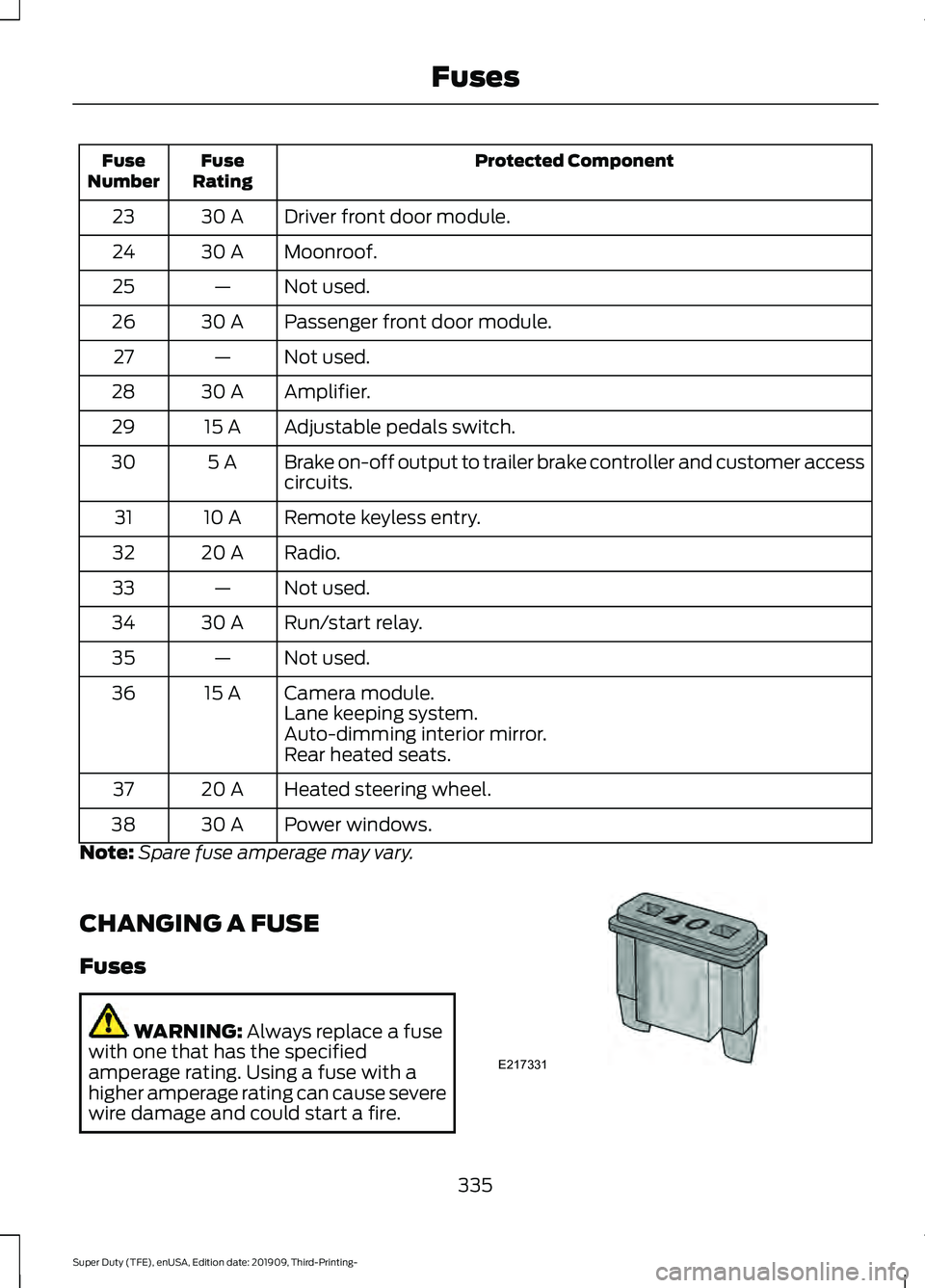
Protected Component
Fuse
Rating
Fuse
Number
Driver front door module.
30 A
23
Moonroof.
30 A
24
Not used.
—
25
Passenger front door module.
30 A
26
Not used.
—
27
Amplifier.
30 A
28
Adjustable pedals switch.
15 A
29
Brake on-off output to trailer brake controller and customer access
circuits.
5 A
30
Remote keyless entry.
10 A
31
Radio.
20 A
32
Not used.
—
33
Run/start relay.
30 A
34
Not used.
—
35
Camera module.
15 A
36
Lane keeping system.
Auto-dimming interior mirror.
Rear heated seats.
Heated steering wheel.
20 A
37
Power windows.
30 A
38
Note: Spare fuse amperage may vary.
CHANGING A FUSE
Fuses WARNING: Always replace a fuse
with one that has the specified
amperage rating. Using a fuse with a
higher amperage rating can cause severe
wire damage and could start a fire. 335
Super Duty (TFE), enUSA, Edition date: 201909, Third-Printing- FusesE217331
Page 550 of 631
AUXILIARY SWITCHES
For maximum vehicle performance, keep
the following information in mind when
adding accessories or equipment to your
vehicle:
•
When adding accessories, equipment,
passengers and luggage to your
vehicle, do not exceed the total weight
capacity of the vehicle or of the front
or rear axle (GVWR or GAWR as
indicated on the Safety Compliance
Certification label). Ask an authorized
dealer for specific weight information.
• The Federal Communications
Commission (FCC) and Canadian
Radio Telecommunications
Commission (CRTC) regulate the use
of mobile communications systems
equipped with radio transmitters, for
example, two-way radios, telephones
and theft alarms. Any such equipment
installed in your vehicle should comply
with Federal Communications
Commission (FCC) and Canadian
Radio Telecommunications
Commission (CRTC) regulations, and
should be installed by an authorized
dealer.
• An authorized dealer needs to install
mobile communications systems.
Improper installation may harm the
operation of your vehicle, particularly
if the manufacturer did not design the
mobile communication system
specifically for automotive use.
• If you or an authorized Ford dealer add
any non-Ford electrical or electronic
accessories or components to your
vehicle, you may adversely affect
battery performance and durability. In
addition, you may also adversely affect
the performance of other electrical
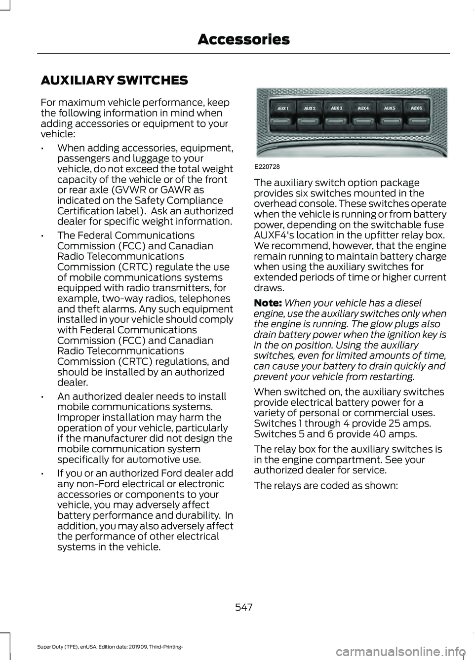
systems in the vehicle. The auxiliary switch option package
provides six switches mounted in the
overhead console. These switches operate
when the vehicle is running or from battery
power, depending on the switchable fuse
AUXF4's location in the upfitter relay box.
We recommend, however, that the engine
remain running to maintain battery charge
when using the auxiliary switches for
extended periods of time or higher current
draws.
Note:
When your vehicle has a diesel
engine, use the auxiliary switches only when
the engine is running. The glow plugs also
drain battery power when the ignition key is
in the on position. Using the auxiliary
switches, even for limited amounts of time,
can cause your battery to drain quickly and
prevent your vehicle from restarting.
When switched on, the auxiliary switches
provide electrical battery power for a
variety of personal or commercial uses.
Switches 1 through 4 provide 25 amps.
Switches 5 and 6 provide 40 amps.
The relay box for the auxiliary switches is
in the engine compartment. See your
authorized dealer for service.
The relays are coded as shown:
547
Super Duty (TFE), enUSA, Edition date: 201909, Third-Printing- AccessoriesE220728
Page 553 of 631
Upfitter Interface Module (If Equipped)
The Upfitter Interface Module (UIM) is an
electronic control module that operates
equipment (such as lift buckets, cranes,
motors, salt spreaders and snow plows)
with external relays.
If you replace the module, it will require
additional programming by the upfitter.
Obtain this data directly from the upfitter
company. The upfitter contact information
is in the vehicle door opening.
For more information on the Upfitter
Interface Module and the auxiliary
switches, contact your upfitter.
550
Super Duty (TFE), enUSA, Edition date: 201909, Third-Printing- Accessories