clutch FORD F-650/750 2018 Owners Manual
[x] Cancel search | Manufacturer: FORD, Model Year: 2018, Model line: F-650/750, Model: FORD F-650/750 2018Pages: 386, PDF Size: 9.01 MB
Page 19 of 386
PROTECTING THE
ENVIRONMENT
You should play your part in protecting the
environment. Correct vehicle usage and
the authorized disposal of waste, cleaning
and lubrication materials are significant
steps toward this aim.
For details about Ford Motor
Company's sustainability progress and
initiatives visit:
Web Address
www.sustainability.ford.com
NOISE POLLUTION CONTROL
In order to keep to the federal exterior
noise regulations, your vehicle may be
equipped with noise emission items.
Depending on your vehicle configuration,
it may have all or some of the following
items:
Air Intake System
Inspect the air cleaner. Do not alter its
location. Do not alter inlet and outlet
piping.
Body
Inspect wheel well splash shields, cab
shields and under hood insulation for
deterioration, dislocation and orientation.
Cooling System
• Inspect the fan for blade damage. If
you find any damage, replace with the
recommended parts. Inspect for
fan-to-shroud interference and any
damage to shroud, such as cracks and
holes.
• Do not change fan ratio or alter fan
spacer dimensions and positions. •
Inspect fan clutch for proper operation.
Make sure the fan is disengaged when
cooling of the engine is not required.
• Inspect radiator shutters (if equipped)
for proper operation. The shutters
should be open during normal
operating temperatures.
Engine
Valve covers and block covers damp-out
engine mechanical noise. If they need
replacing, make sure to replace them with
the recommended parts. Check for
mechanical isolations.
Transmission Enclosure
Inspect for cracks, holes and tears. Clean
any deposits, such as oil, dirt and stones.
Exhaust System
• Inspect for leaks at various joint
connections and loose clamps.
• Perform a visual inspection for cracks
or holes in the muffler and tail pipe.
• Always use the recommended
replacement parts.
• Do not change the tail pipe elbow or
offset tail pipe orientation from the
standard position as originally received.
• To avoid abnormal changes in vehicle
sound levels, it is necessary for the
owner to perform inspections and
necessary maintenance at specified
intervals. See Scheduled
Maintenance (page 320).
16
F650750 (TBC) , enUSA, Edition date: 201708, First Printing Environment
Page 118 of 386
Forced downshifts
•
Allowed in drive (D) with the tow/haul
feature on or off.
• Press the accelerator to the floor.
• Allows transmission to select an
appropriate gear.
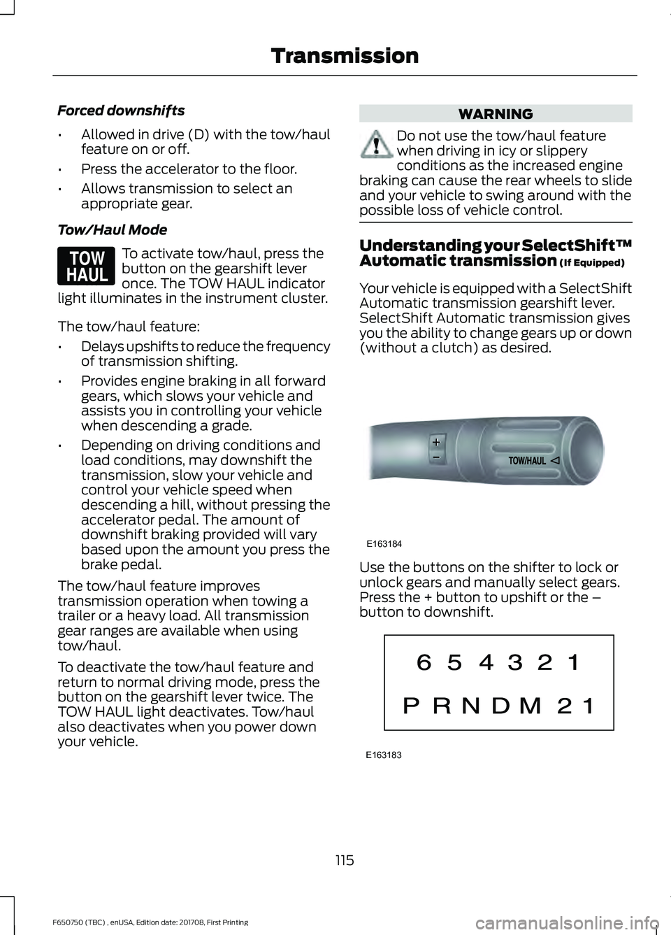
Tow/Haul Mode To activate tow/haul, press the
button on the gearshift lever
once. The TOW HAUL indicator
light illuminates in the instrument cluster.
The tow/haul feature:
• Delays upshifts to reduce the frequency
of transmission shifting.
• Provides engine braking in all forward
gears, which slows your vehicle and
assists you in controlling your vehicle
when descending a grade.
• Depending on driving conditions and
load conditions, may downshift the
transmission, slow your vehicle and
control your vehicle speed when
descending a hill, without pressing the
accelerator pedal. The amount of
downshift braking provided will vary
based upon the amount you press the
brake pedal.
The tow/haul feature improves
transmission operation when towing a
trailer or a heavy load. All transmission
gear ranges are available when using
tow/haul.
To deactivate the tow/haul feature and
return to normal driving mode, press the
button on the gearshift lever twice. The
TOW HAUL light deactivates. Tow/haul
also deactivates when you power down
your vehicle. WARNING
Do not use the tow/haul feature
when driving in icy or slippery
conditions as the increased engine
braking can cause the rear wheels to slide
and your vehicle to swing around with the
possible loss of vehicle control. Understanding your SelectShift™
Automatic transmission (If Equipped)
Your vehicle is equipped with a SelectShift
Automatic transmission gearshift lever.
SelectShift Automatic transmission gives
you the ability to change gears up or down
(without a clutch) as desired. Use the buttons on the shifter to lock or
unlock gears and manually select gears.
Press the + button to upshift or the –
button to downshift.
115
F650750 (TBC) , enUSA, Edition date: 201708, First Printing TransmissionE161509 E163184 E163183
Page 129 of 386
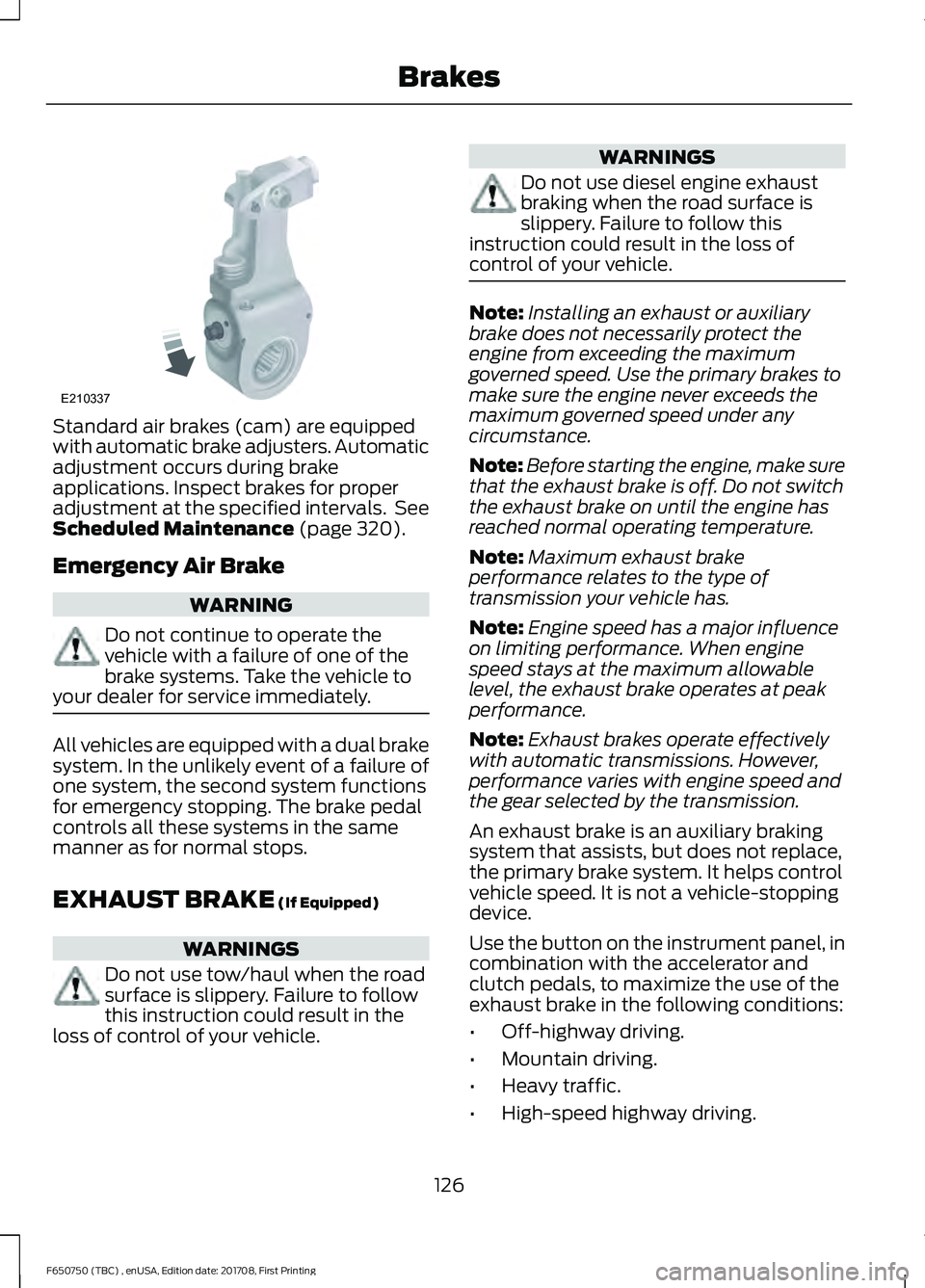
Standard air brakes (cam) are equipped
with automatic brake adjusters. Automatic
adjustment occurs during brake
applications. Inspect brakes for proper
adjustment at the specified intervals. See
Scheduled Maintenance (page 320).
Emergency Air Brake WARNING
Do not continue to operate the
vehicle with a failure of one of the
brake systems. Take the vehicle to
your dealer for service immediately. All vehicles are equipped with a dual brake
system. In the unlikely event of a failure of
one system, the second system functions
for emergency stopping. The brake pedal
controls all these systems in the same
manner as for normal stops.
EXHAUST BRAKE
(If Equipped)
WARNINGS
Do not use tow/haul when the road
surface is slippery. Failure to follow
this instruction could result in the
loss of control of your vehicle. WARNINGS
Do not use diesel engine exhaust
braking when the road surface is
slippery. Failure to follow this
instruction could result in the loss of
control of your vehicle. Note:
Installing an exhaust or auxiliary
brake does not necessarily protect the
engine from exceeding the maximum
governed speed. Use the primary brakes to
make sure the engine never exceeds the
maximum governed speed under any
circumstance.
Note: Before starting the engine, make sure
that the exhaust brake is off. Do not switch
the exhaust brake on until the engine has
reached normal operating temperature.
Note: Maximum exhaust brake
performance relates to the type of
transmission your vehicle has.
Note: Engine speed has a major influence
on limiting performance. When engine
speed stays at the maximum allowable
level, the exhaust brake operates at peak
performance.
Note: Exhaust brakes operate effectively
with automatic transmissions. However,
performance varies with engine speed and
the gear selected by the transmission.
An exhaust brake is an auxiliary braking
system that assists, but does not replace,
the primary brake system. It helps control
vehicle speed. It is not a vehicle-stopping
device.
Use the button on the instrument panel, in
combination with the accelerator and
clutch pedals, to maximize the use of the
exhaust brake in the following conditions:
• Off-highway driving.
• Mountain driving.
• Heavy traffic.
• High-speed highway driving.
126
F650750 (TBC) , enUSA, Edition date: 201708, First Printing BrakesE210337
Page 130 of 386
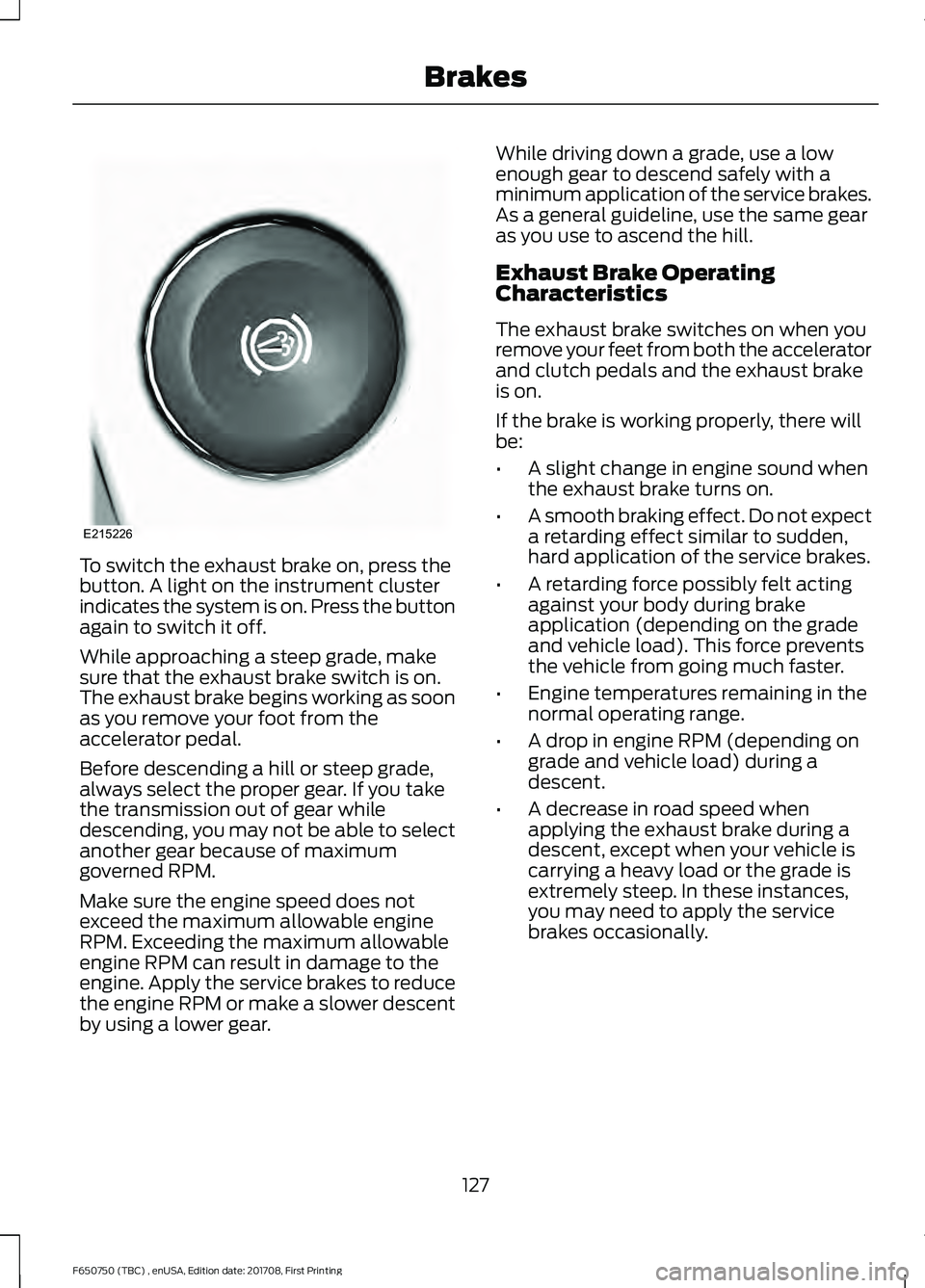
To switch the exhaust brake on, press the
button. A light on the instrument cluster
indicates the system is on. Press the button
again to switch it off.
While approaching a steep grade, make
sure that the exhaust brake switch is on.
The exhaust brake begins working as soon
as you remove your foot from the
accelerator pedal.
Before descending a hill or steep grade,
always select the proper gear. If you take
the transmission out of gear while
descending, you may not be able to select
another gear because of maximum
governed RPM.
Make sure the engine speed does not
exceed the maximum allowable engine
RPM. Exceeding the maximum allowable
engine RPM can result in damage to the
engine. Apply the service brakes to reduce
the engine RPM or make a slower descent
by using a lower gear. While driving down a grade, use a low
enough gear to descend safely with a
minimum application of the service brakes.
As a general guideline, use the same gear
as you use to ascend the hill.
Exhaust Brake Operating
Characteristics
The exhaust brake switches on when you
remove your feet from both the accelerator
and clutch pedals and the exhaust brake
is on.
If the brake is working properly, there will
be:
•
A slight change in engine sound when
the exhaust brake turns on.
• A smooth braking effect. Do not expect
a retarding effect similar to sudden,
hard application of the service brakes.
• A retarding force possibly felt acting
against your body during brake
application (depending on the grade
and vehicle load). This force prevents
the vehicle from going much faster.
• Engine temperatures remaining in the
normal operating range.
• A drop in engine RPM (depending on
grade and vehicle load) during a
descent.
• A decrease in road speed when
applying the exhaust brake during a
descent, except when your vehicle is
carrying a heavy load or the grade is
extremely steep. In these instances,
you may need to apply the service
brakes occasionally.
127
F650750 (TBC) , enUSA, Edition date: 201708, First Printing BrakesE215226
Page 169 of 386
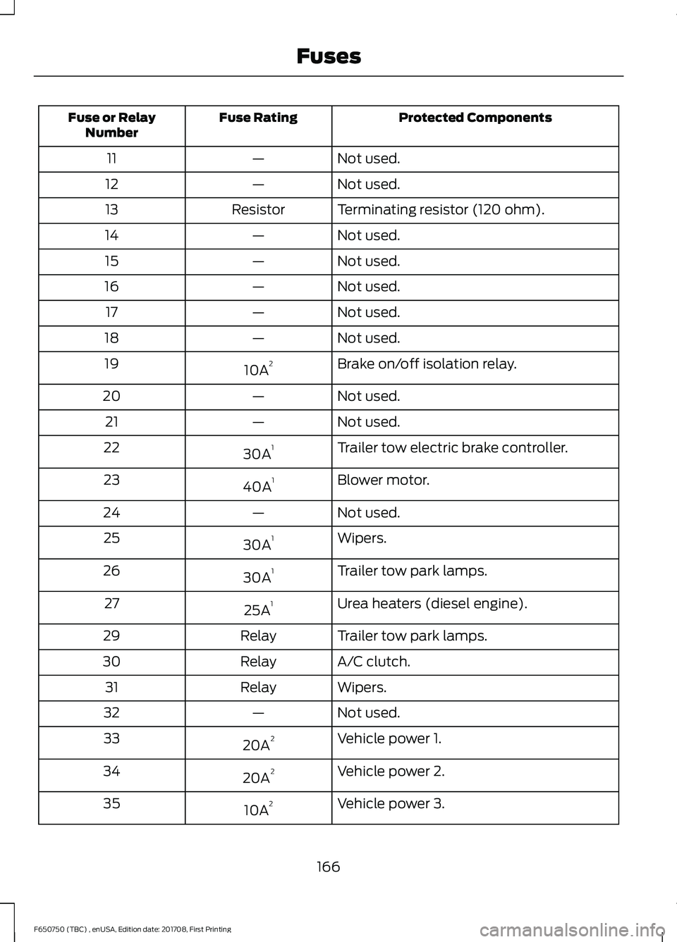
Protected Components
Fuse Rating
Fuse or Relay
Number
Not used.
—
11
Not used.
—
12
Terminating resistor (120 ohm).
Resistor
13
Not used.
—
14
Not used.
—
15
Not used.
—
16
Not used.
—
17
Not used.
—
18
Brake on/off isolation relay.
10A 2
19
Not used.
—
20
Not used.
—
21
Trailer tow electric brake controller.
30A 1
22
Blower motor.
40A 1
23
Not used.
—
24
Wipers.
30A 1
25
Trailer tow park lamps.
30A 1
26
Urea heaters (diesel engine).
25A 1
27
Trailer tow park lamps.
Relay
29
A/C clutch.
Relay
30
Wipers.
Relay
31
Not used.
—
32
Vehicle power 1.
20A 2
33
Vehicle power 2.
20A 2
34
Vehicle power 3.
10A 2
35
166
F650750 (TBC) , enUSA, Edition date: 201708, First Printing Fuses
Page 170 of 386
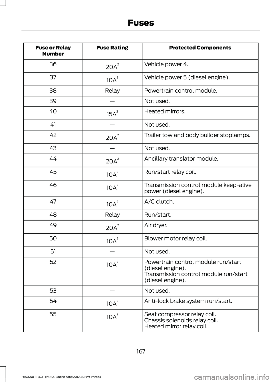
Protected Components
Fuse Rating
Fuse or Relay
Number
Vehicle power 4.
20A 2
36
Vehicle power 5 (diesel engine).
10A 2
37
Powertrain control module.
Relay
38
Not used.
—
39
Heated mirrors.
15A 2
40
Not used.
—
41
Trailer tow and body builder stoplamps.
20A 2
42
Not used.
—
43
Ancillary translator module.
20A 2
44
Run/start relay coil.
10A 2
45
Transmission control module keep-alive
power (diesel engine).
10A 2
46
A/C clutch.
10A 2
47
Run/start.
Relay
48
Air dryer.
20A 2
49
Blower motor relay coil.
10A 2
50
Not used.
—
51
Powertrain control module run/start
(diesel engine).
10A 2
52
Transmission control module run/start
(diesel engine).
Not used.
—
53
Anti-lock brake system run/start.
10A 2
54
Seat compressor relay coil.
10A 2
55
Chassis solenoids relay coil.
Heated mirror relay coil.
167
F650750 (TBC) , enUSA, Edition date: 201708, First Printing Fuses
Page 179 of 386
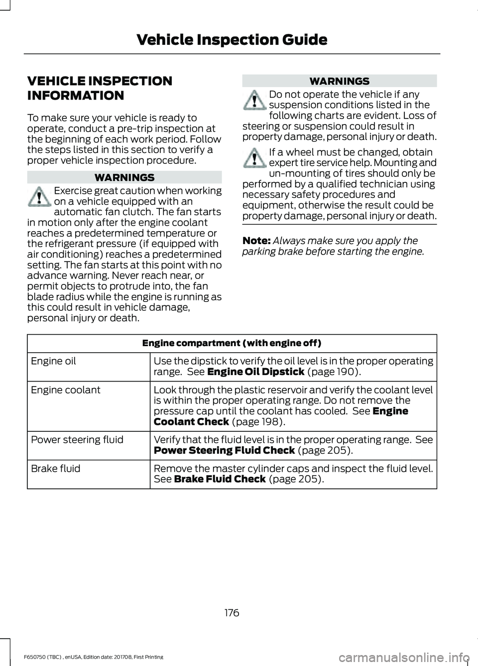
VEHICLE INSPECTION
INFORMATION
To make sure your vehicle is ready to
operate, conduct a pre-trip inspection at
the beginning of each work period. Follow
the steps listed in this section to verify a
proper vehicle inspection procedure.
WARNINGS
Exercise great caution when working
on a vehicle equipped with an
automatic fan clutch. The fan starts
in motion only after the engine coolant
reaches a predetermined temperature or
the refrigerant pressure (if equipped with
air conditioning) reaches a predetermined
setting. The fan starts at this point with no
advance warning. Never reach near, or
permit objects to protrude into, the fan
blade radius while the engine is running as
this could result in vehicle damage,
personal injury or death. WARNINGS
Do not operate the vehicle if any
suspension conditions listed in the
following charts are evident. Loss of
steering or suspension could result in
property damage, personal injury or death. If a wheel must be changed, obtain
expert tire service help. Mounting and
un-mounting of tires should only be
performed by a qualified technician using
necessary safety procedures and
equipment, otherwise the result could be
property damage, personal injury or death. Note:
Always make sure you apply the
parking brake before starting the engine. Engine compartment (with engine off)
Use the dipstick to verify the oil level is in the proper operating
range. See Engine Oil Dipstick (page 190).
Engine oil
Look through the plastic reservoir and verify the coolant level
is within the proper operating range. Do not remove the
pressure cap until the coolant has cooled. See
Engine
Coolant Check (page 198).
Engine coolant
Verify that the fluid level is in the proper operating range. See
Power Steering Fluid Check
(page 205).
Power steering fluid
Remove the master cylinder caps and inspect the fluid level.
See
Brake Fluid Check (page 205).
Brake fluid
176
F650750 (TBC) , enUSA, Edition date: 201708, First Printing Vehicle Inspection Guide
Page 188 of 386
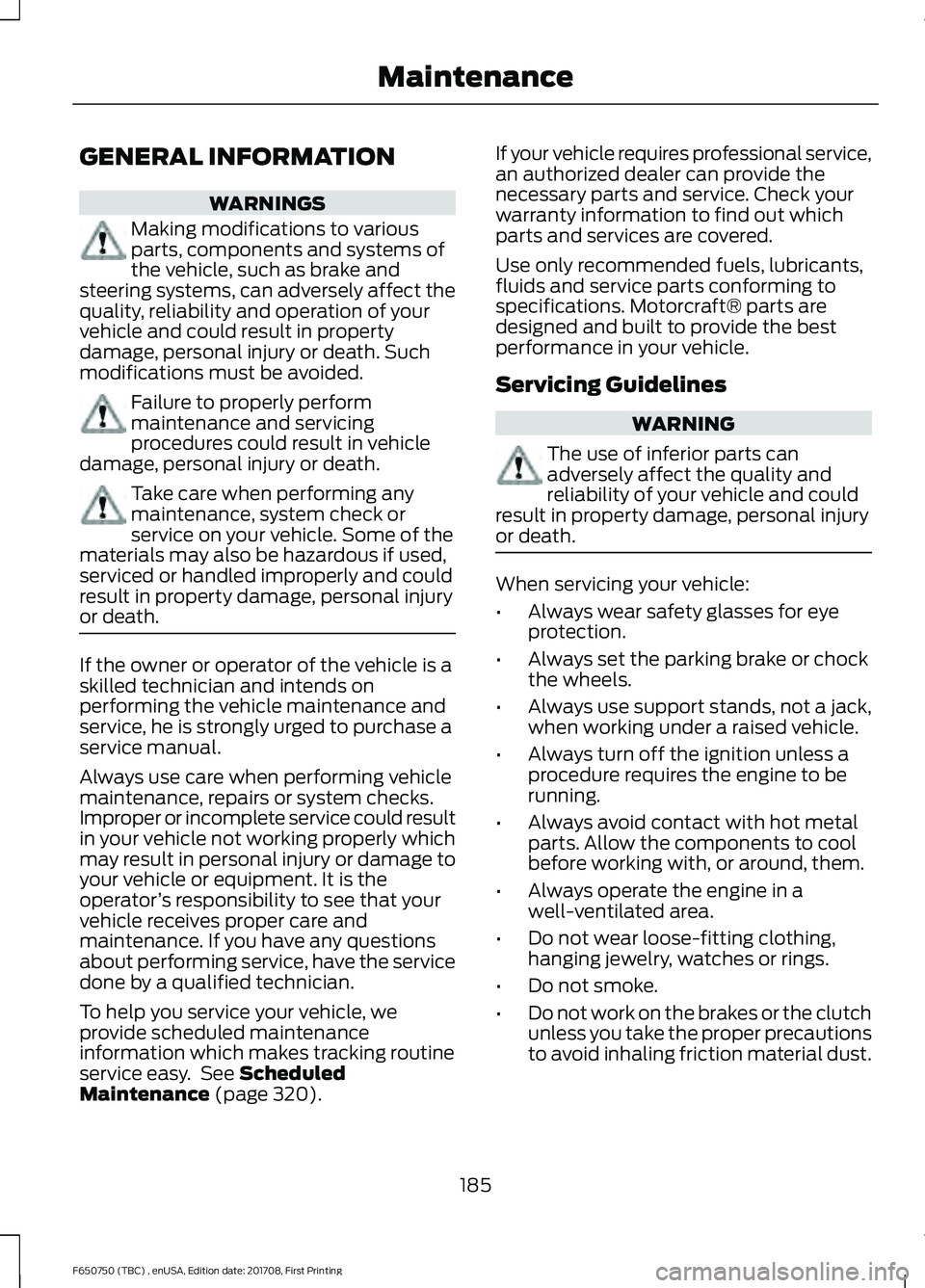
GENERAL INFORMATION
WARNINGS
Making modifications to various
parts, components and systems of
the vehicle, such as brake and
steering systems, can adversely affect the
quality, reliability and operation of your
vehicle and could result in property
damage, personal injury or death. Such
modifications must be avoided. Failure to properly perform
maintenance and servicing
procedures could result in vehicle
damage, personal injury or death. Take care when performing any
maintenance, system check or
service on your vehicle. Some of the
materials may also be hazardous if used,
serviced or handled improperly and could
result in property damage, personal injury
or death. If the owner or operator of the vehicle is a
skilled technician and intends on
performing the vehicle maintenance and
service, he is strongly urged to purchase a
service manual.
Always use care when performing vehicle
maintenance, repairs or system checks.
Improper or incomplete service could result
in your vehicle not working properly which
may result in personal injury or damage to
your vehicle or equipment. It is the
operator
’s responsibility to see that your
vehicle receives proper care and
maintenance. If you have any questions
about performing service, have the service
done by a qualified technician.
To help you service your vehicle, we
provide scheduled maintenance
information which makes tracking routine
service easy. See Scheduled
Maintenance (page 320). If your vehicle requires professional service,
an authorized dealer can provide the
necessary parts and service. Check your
warranty information to find out which
parts and services are covered.
Use only recommended fuels, lubricants,
fluids and service parts conforming to
specifications. Motorcraft® parts are
designed and built to provide the best
performance in your vehicle.
Servicing Guidelines
WARNING
The use of inferior parts can
adversely affect the quality and
reliability of your vehicle and could
result in property damage, personal injury
or death. When servicing your vehicle:
•
Always wear safety glasses for eye
protection.
• Always set the parking brake or chock
the wheels.
• Always use support stands, not a jack,
when working under a raised vehicle.
• Always turn off the ignition unless a
procedure requires the engine to be
running.
• Always avoid contact with hot metal
parts. Allow the components to cool
before working with, or around, them.
• Always operate the engine in a
well-ventilated area.
• Do not wear loose-fitting clothing,
hanging jewelry, watches or rings.
• Do not smoke.
• Do not work on the brakes or the clutch
unless you take the proper precautions
to avoid inhaling friction material dust.
185
F650750 (TBC) , enUSA, Edition date: 201708, First Printing Maintenance
Page 201 of 386
•
Robinair® Coolant and Battery
Refractometer 75240 –
Recommended refractometer to test
coolant concentration. (Rotunda tool
part number: ROB75240).
• Rotunda 328-R071–ELC (Antifreeze
Coolant ELC Contamination Kit)
–
Evaluates the corrosion inhibitor
additive strength. Note the first step is
to verify the vehicle ’s coolant
concentration is in the correct range of
40 – 60%. Coolant concentrations
outside this range will not provide valid
test results. If the report results in a
pass, for example the cooling system
does not show excessive
contamination, the corrosion inhibitor
additive strength is sufficient, and no
action is required. If the report results
as insufficient (does not pass), the
corrosion inhibitor additive strength of
the coolant is too low. If the engine
cooling system corrosion inhibitor
additive strength is low, add
47 fl oz
(1.4 L) of Motorcraft Specialty Orange
Engine Coolant Revitalizer. If the
secondary cooling system corrosion
inhibitor additive strength is low, add
16 fl oz (0.47 L) of Motorcraft Specialty
Orange Engine Coolant Revitalizer.
• Motorcraft Specialty Orange Engine
Coolant Revitalizer
– Additive to
boost the corrosion inhibitor level
based upon the test results of the
Antifreeze Coolant ELC Contamination
Kit. The Revitalizer may be added two
times over the life of the coolant. If
additional dosages are required, the
cooling system must be flushed and
refilled per the instructions in the
Workshop Manual.
Make sure to follow the proper coolant and
additive specifications. See
Capacities
and Specifications (page 255). Coolant Change
At specific mileage intervals, as listed in
the scheduled maintenance information,
the coolant should be changed. The
information display may display a message
to change coolant at this time. Add
prediluted coolant approved to the correct
specification. See
Capacities and
Specifications (page 255).
Engine-driven Cooling Fan (Fan
Clutch)
Your vehicle may have an engine driven
cooling fan drive (also called a fan clutch).
This fan drive changes the fan speed to
match the vehicle ’s changing cooling air
flow requirements. Fan speed, fan noise
level and fuel consumption all will increase
based on the driving conditions that
include trailer towing, hill climbing, heavy
loads, high speed and high ambient
temperature, individually or in combination.
The fan drive is designed to provide the
minimum fan speed (and resulting
minimum fan noise and fuel consumption)
required to meet the ever changing vehicle
cooling air flow requirements. You will hear
the amount of fan noise increasing and
decreasing as the engine power
requirements and vehicle driving conditions
change as you drive. This is to be expected
as being normal to the operation of your
vehicle. High levels of fan noise might also
be heard when your engine is first started,
and should normally decrease after driving
for a short time.
ENGINE COOLANT CHECK -
6.8L WARNINGS
Never remove the coolant reservoir
cap when the engine is running or
hot.
198
F650750 (TBC) , enUSA, Edition date: 201708, First Printing Maintenance
Page 204 of 386
Severe Climates
If you drive in extremely cold climates:
•
It may be necessary to increase the
coolant concentration above 50%.
• A coolant concentration of 60%
provides improved freeze point
protection. Coolant concentrations
above 60% decrease the overheat
protection characteristics of the
coolant and may cause engine
damage.
If you drive in extremely hot climates:
• You can decrease the coolant
concentration to 40%.
• Coolant concentrations below 40%
decrease the freeze and corrosion
protection characteristics of the
coolant and may cause engine
damage.
Vehicles driven year-round in non-extreme
climates should use prediluted engine
coolant for optimum cooling system and
engine protection.
Coolant Change
At specific mileage intervals, as listed in
the scheduled maintenance information,
the coolant should be changed. The
information display may display a message
to change coolant at this time. Add
prediluted coolant approved to the correct
specification. See Capacities and
Specifications (page 255). Engine-driven Cooling Fan (Fan
Clutch)
Your vehicle is equipped with an engine
driven cooling fan drive (also called a fan
clutch). This fan drive changes the fan
speed to match the vehicle
’s changing
cooling air flow requirements. Fan speed,
fan noise level and fuel consumption all
will increase based on the driving
conditions that include trailer towing, hill
climbing, heavy loads, high speed and high
ambient temperature, individually or in
combination.
The fan drive is designed to provide the
minimum fan speed (and resulting
minimum fan noise and fuel consumption)
required to meet the ever changing vehicle
cooling air flow requirements. You will hear
the amount of fan noise increasing and
decreasing as the engine power
requirements and vehicle driving conditions
change as you drive. This is to be expected
as being normal to the operation of your
vehicle. High levels of fan noise might also
be heard when your engine is first started,
and should normally decrease after driving
for a short time.
Fail-Safe Cooling
Fail-safe cooling allows you to temporarily
drive your vehicle before any incremental
component damage occurs. The fail-safe
distance depends on ambient
temperature, vehicle load and terrain.
How Fail-Safe Cooling Works
If the engine begins to overheat, the
coolant temperature gauge moves toward
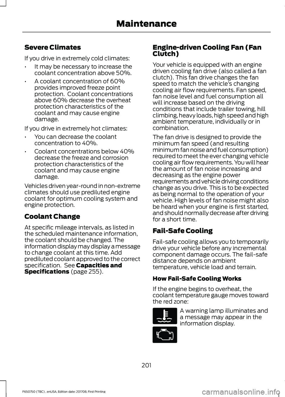
the red zone: A warning lamp illuminates and
a message may appear in the
information display.
201
F650750 (TBC) , enUSA, Edition date: 201708, First Printing Maintenance