instrument cluster FORD F SERIES MOTORHOME AND COMMERCIAL CHASSIS 2004 11.G Owners Manual
[x] Cancel search | Manufacturer: FORD, Model Year: 2004, Model line: F SERIES MOTORHOME AND COMMERCIAL CHASSIS, Model: FORD F SERIES MOTORHOME AND COMMERCIAL CHASSIS 2004 11.GPages: 120, PDF Size: 2.21 MB
Page 25 of 120
•The anti-lock system does not reduce stopping distance. Always leave
enough room between your vehicle and the vehicle in front of you to
stop.
•We recommend that you familiarize yourself with this braking
technique. However, avoid taking any unnecessary risks.
Hydraulic brake booster system (Hydroboost or Hydromax)
The Hydroboost and Hydromax systems receive fluid pressure from the
power steering pump to provide power assist during braking.
The Hydromax booster receives backup pressure from the reserve
system electric pump whenever the fluid in the power steering system is
not flowing. When the engine is OFF, the pump will turn on if the brake
pedal is applied, or if the ignition is turned to the ON position.
The sound of the pump operating may be heard by the driver, but this is
a normal characteristic of the system.
The reserve system provides reduced braking power, so the vehicle
should be operated under these conditions with caution, and only to seek
service repair and remove the vehicle from the roadway.
For Hydromax-equipped vehicles operating under normal
conditions,the noise of the fluid flowing through the booster may be
heard whenever the brake is applied. This condition is normal. Vehicle
service is not required.
If braking performance or pedal response becomes very poor, even when
the pedal is strongly depressed, it may indicate the presence of air in the
hydraulic system or leakage of fluid. Stop the vehicle safely as soon as
possible and seek service immediately.
ABS warning lamp
The
ABSwarning lamp in the instrument cluster momentarily illuminates
when the ignition is turned to the ON position. If the light remains on
after the vehicle is started, continues to flash or fails to illuminate, have
the system serviced immediately. With the ABS light on, the anti-lock
brake system is disabled and normal braking is still effective unless the
brake warning light also remains illuminated.
With the ABS light on, the anti-lock
brake system is disabled and normal
braking is still effective unless the
brake warning light also remains
illuminated with parking brake released. (If your brake warning lamp
illuminates, have your vehicle serviced immediately.)
2004 Motorhome(mot)
Supplement
USA English(fus)
Driving
25
Page 26 of 120
Parking brake
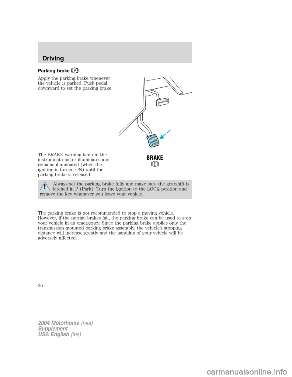
Apply the parking brake whenever
the vehicle is parked. Push pedal
downward to set the parking brake.
The BRAKE warning lamp in the
instrument cluster illuminates and
remains illuminated (when the
ignition is turned ON) until the
parking brake is released.
Always set the parking brake fully and make sure the gearshift is
latched in P (Park). Turn the ignition to the LOCK position and
remove the key whenever you leave your vehicle.
The parking brake is not recommended to stop a moving vehicle.
However, if the normal brakes fail, the parking brake can be used to stop
your vehicle in an emergency. Since the parking brake applies only the
transmission mounted parking brake assembly, the vehicle’s stopping
distance will increase greatly and the handling of your vehicle will be
adversely affected.
2004 Motorhome(mot)
Supplement
USA English(fus)
Driving
26
Page 43 of 120
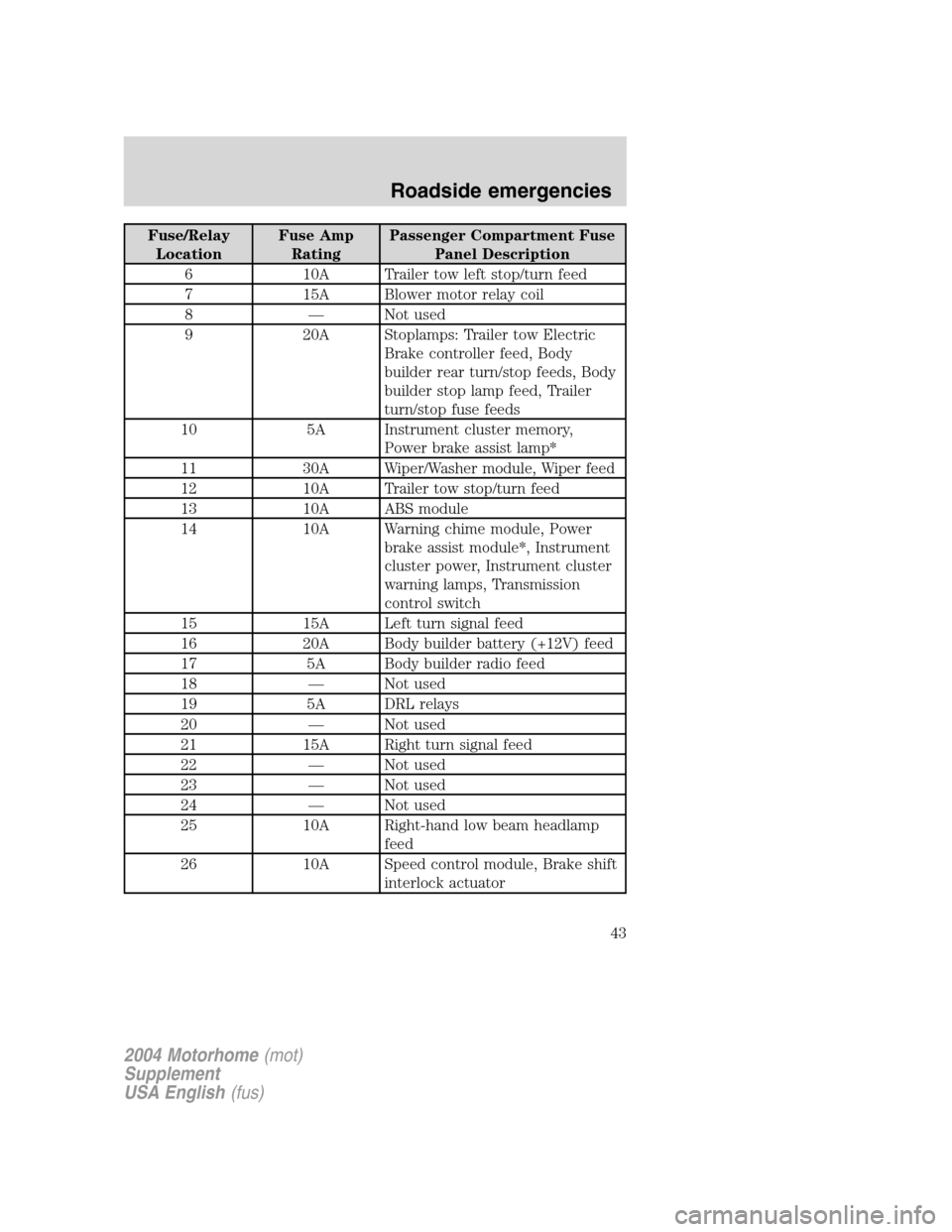
Fuse/Relay
LocationFuse Amp
RatingPassenger Compartment Fuse
Panel Description
6 10A Trailer tow left stop/turn feed
7 15A Blower motor relay coil
8—Not used
9 20A Stoplamps: Trailer tow Electric
Brake controller feed, Body
builder rear turn/stop feeds, Body
builder stop lamp feed, Trailer
turn/stop fuse feeds
10 5A Instrument cluster memory,
Power brake assist lamp*
11 30A Wiper/Washer module, Wiper feed
12 10A Trailer tow stop/turn feed
13 10A ABS module
14 10A Warning chime module, Power
brake assist module*, Instrument
cluster power, Instrument cluster
warning lamps, Transmission
control switch
15 15A Left turn signal feed
16 20A Body builder battery (+12V) feed
17 5A Body builder radio feed
18—Not used
19 5A DRL relays
20—Not used
21 15A Right turn signal feed
22—Not used
23—Not used
24—Not used
25 10A Right-hand low beam headlamp
feed
26 10A Speed control module, Brake shift
interlock actuator
2004 Motorhome(mot)
Supplement
USA English(fus)
Roadside emergencies
43
Page 82 of 120
Cleaner air
Ford endorses the use of reformulated“cleaner-burning”gasolines to
improve air quality.
Running out of fuel
Avoid running out of fuel because this situation may have an adverse
affect on powertrain components.
If you have run out of fuel:
•You may need to cycle the ignition from OFF to ON several times after
refueling, to allow the fuel system to pump the fuel from the tank to
the engine.
•Your“Service Engine Soon”indicator may come on. For more
information on the“Service Engine Soon”indicator, refer to the
Instrument clusterchapter.
Fuel filter replacement
The fuel filter assembly is located inside the driver side frame rail, near
the transmission.
The fuel filter should be replaced every 24 000 km (15 000 miles).
Removal
If the fuel filter is being serviced with the rear of the vehicle
higher than the front, or if the fuel tank is pressurized, fuel
leakage or siphoning from the tank fuel tubes could occur. To prevent
this condition, maintain the vehicle front end at or above the level of
the rear of the vehicle.
Do not smoke or carry lighted tobacco or open flame of any type
when working on or near any fuel related component. Highly
flammable mixtures are always present and may be ignited, resulting in
possible personal injury.
Fuel in the fuel system remains under high pressure even when
the engine is not running. Before servicing or disconnecting any
of the fuel lines or fuel system components, the fuel system pressure
must be relieved in order to prevent accidental spraying of fuel,
causing personal injury or a fire hazard.
2004 Motorhome(mot)
Supplement
USA English(fus)
Maintenance and specifications
82
Page 89 of 120
Readiness for Inspection/Maintenance (I/M) testing
In some localities, it may be a legal requirement to pass an I/M test of
the on-board diagnostics system. If your“Check Engine/Service Engine
Soon”light is on, refer to the description in theWarning lights and
chimessection of theInstrument clusterchapter. Your vehicle may not
pass the I/M test with the“Check Engine/Service Engine Soon”light on.
If the vehicle’s powertrain system or its battery has just been serviced,
the on-board diagnostics system is reset to a“not ready for I/M test”
condition. To ready the on-board diagnostics system for I/M testing, a
minimum of 30 minutes of city and highway driving is necessary as
described below:
•First, at least 10 minutes of driving on an expressway or highway.
•Next, at least 20 minutes driving in stop-and-go, city-type traffic with
at least four idle periods.
Allow the vehicle to sit for at least eight hours without starting the
engine. Then, start the engine and complete the above driving cycle. The
engine must warm up to its normal operating temperature. Once started,
do not turn off the engine until the above driving cycle is complete.
On board diagnostics (OBD-II)
Your vehicle is equipped with a computer that monitors the engine’s
emission control system. This system is commonly known as the On
Board Diagnostics System (OBD-II). This OBD-II system protects the
environment by ensuring that your vehicle continues to meet
government emission standards. The OBD-II system also assists the
service technician in properly servicing your vehicle. When theCheck
Engine/Service Engine Soonlight illuminates, the OBD-II system has
detected a malfunction. Temporary malfunctions may cause yourCheck
Engine/Service Engine Soonlight to illuminate. Examples are:
1.
The vehicle has run out of fuel. (The engine may misfire or run poorly.)
2. Poor fuel quality or water in the fuel.
3. The fuel cap may not have been securely tightened.
These temporary malfunctions can be corrected by filling the fuel tank
with good quality fuel and/or properly tightening the fuel cap. After three
driving cycles without these or any other temporary malfunctions
present, theCheck Engine/Service Engine Soonlight should turn off.
(A driving cycle consists of a cold engine startup followed by mixed
city/highway driving.) No additional vehicle service is required.
If theCheck Engine/Service Engine Soonlight remains on, have your
vehicle serviced at the first available opportunity.
2004 Motorhome(mot)
Supplement
USA English(fus)
Maintenance and specifications
89
Page 118 of 120
Instrument panel
cluster ..........................................8
lighting up panel and
interior .......................................15
J
Jack ..............................................48
positioning .................................48
storage .......................................48
Jump-starting your vehicle ........52
K
Keys
positions of the ignition ...........20
L
Lamps
daytime running light ...............14
headlamps .................................14
headlamps, flash to pass ..........15
instrument panel, dimming .....15
replacing bulbs .........................15
Lights, warning and indicator ......8
anti-lock brakes (ABS) ............25
Load limits .............................31, 33
GAWR ........................................31
GVWR ........................................31
trailer towing ............................31
Lubricant specifications ...112–113
M
Motorcraft parts ..................82, 109
O
Octane rating ..............................81
Oil (see Engine oil) ....................69P
Parking brake ..............................26
Parts (see Motorcraft parts) ....109
Power distribution box
(see Fuses) .................................45
Power steering
fluid, checking and adding ......90
fluid, refill capacity ................110
fluid, specifications .........112–113
R
Relays ....................................41, 48
Roadside assistance ....................39
S
Safety defects, reporting ............65
Servicing your vehicle ................67
Spark plugs,
specifications .............109, 113–114
Special notice ................................5
Specification chart,
lubricants ...........................112–113
Speed control ..............................17
Starting your vehicle ............20–22
jump starting ............................52
Steering wheel
tilting .........................................16
T
Tilt steering wheel ......................16
Tires .......................................48, 96
changing ..............................48, 51
replacing ....................................49
snow tires and chains ............108
2004 Motorhome(mot)
Supplement
USA English(fus)
Index
118