oil FORD F SERIES MOTORHOME AND COMMERCIAL CHASSIS 2004 11.G Owners Manual
[x] Cancel search | Manufacturer: FORD, Model Year: 2004, Model line: F SERIES MOTORHOME AND COMMERCIAL CHASSIS, Model: FORD F SERIES MOTORHOME AND COMMERCIAL CHASSIS 2004 11.GPages: 120, PDF Size: 2.21 MB
Page 2 of 120
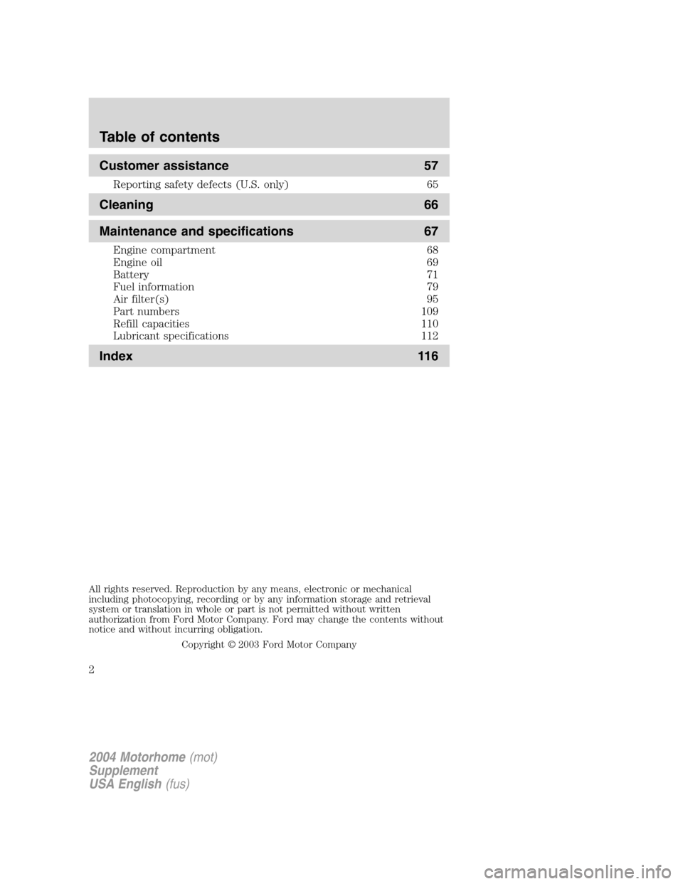
Customer assistance 57
Reporting safety defects (U.S. only) 65
Cleaning 66
Maintenance and specifications 67
Engine compartment 68
Engine oil 69
Battery 71
Fuel information 79
Air filter(s) 95
Part numbers 109
Refill capacities 110
Lubricant specifications 112
Index 116
All rights reserved. Reproduction by any means, electronic or mechanical
including photocopying, recording or by any information storage and retrieval
system or translation in whole or part is not permitted without written
authorization from Ford Motor Company. Ford may change the contents without
notice and without incurring obligation.
Copyright © 2003 Ford Motor Company
2004 Motorhome(mot)
Supplement
USA English(fus)
Table of contents
2
Page 4 of 120
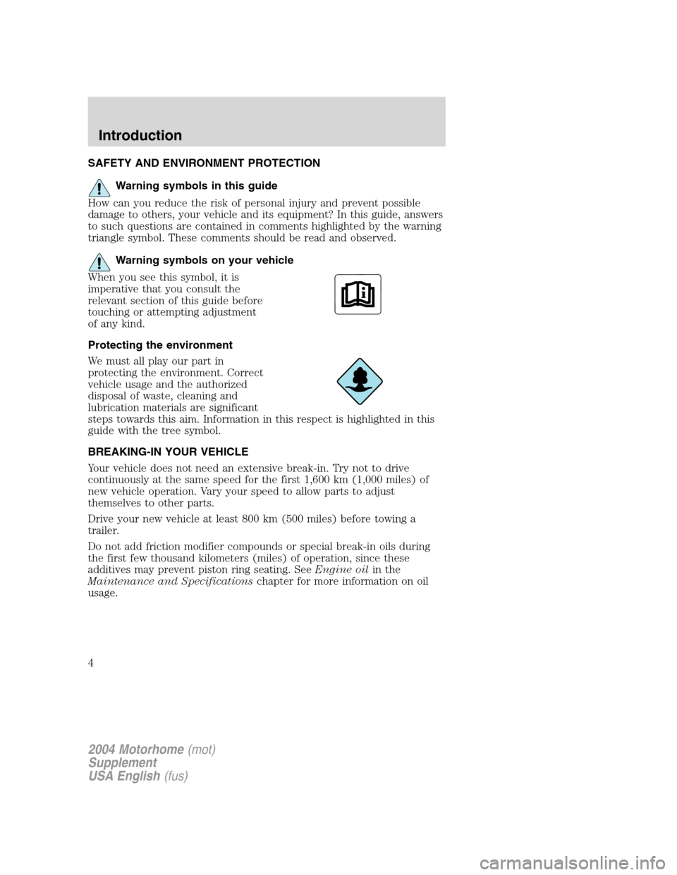
SAFETY AND ENVIRONMENT PROTECTION
Warning symbols in this guide
How can you reduce the risk of personal injury and prevent possible
damage to others, your vehicle and its equipment? In this guide, answers
to such questions are contained in comments highlighted by the warning
triangle symbol. These comments should be read and observed.
Warning symbols on your vehicle
When you see this symbol, it is
imperative that you consult the
relevant section of this guide before
touching or attempting adjustment
of any kind.
Protecting the environment
We must all play our part in
protecting the environment. Correct
vehicle usage and the authorized
disposal of waste, cleaning and
lubrication materials are significant
steps towards this aim. Information in this respect is highlighted in this
guide with the tree symbol.
BREAKING-IN YOUR VEHICLE
Your vehicle does not need an extensive break-in. Try not to drive
continuously at the same speed for the first 1,600 km (1,000 miles) of
new vehicle operation. Vary your speed to allow parts to adjust
themselves to other parts.
Drive your new vehicle at least 800 km (500 miles) before towing a
trailer.
Do not add friction modifier compounds or special break-in oils during
the first few thousand kilometers (miles) of operation, since these
additives may prevent piston ring seating. SeeEngine oilin the
Maintenance and Specificationschapter for more information on oil
usage.
2004 Motorhome(mot)
Supplement
USA English(fus)
Introduction
4
Page 7 of 120
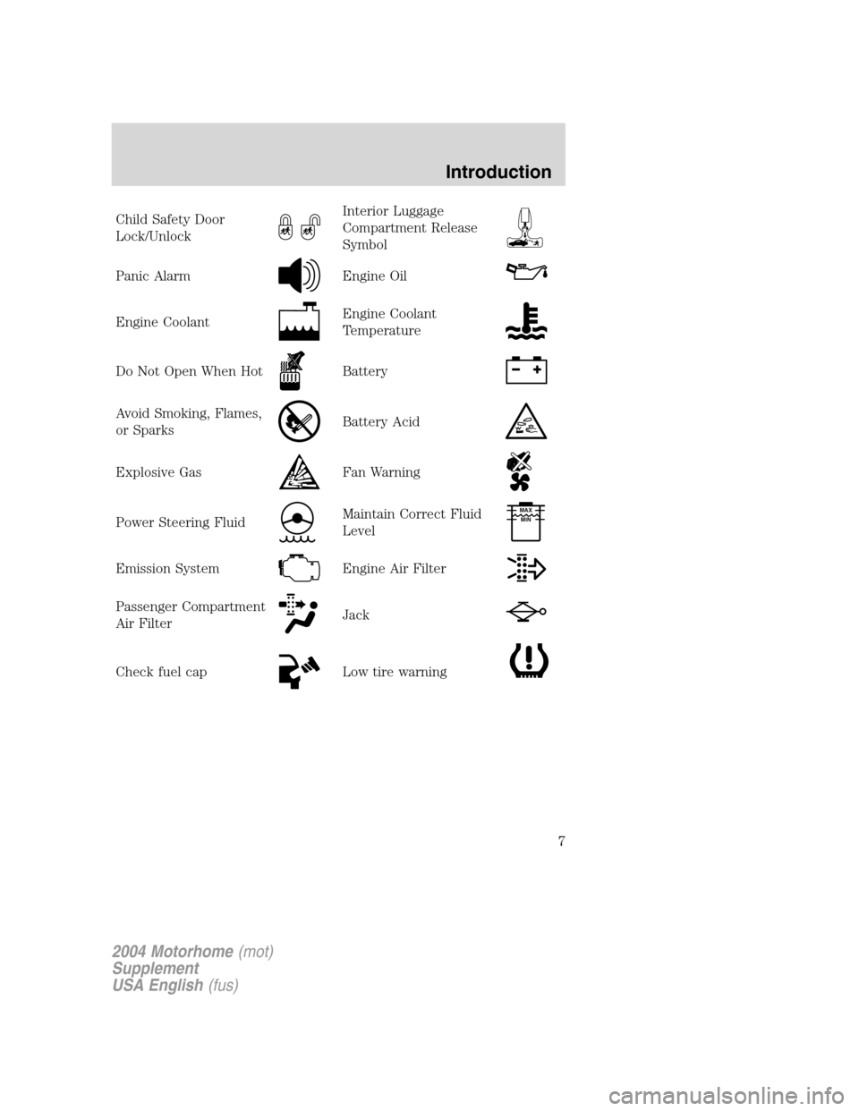
Child Safety Door
Lock/UnlockInterior Luggage
Compartment Release
Symbol
Panic AlarmEngine Oil
Engine CoolantEngine Coolant
Temperature
Do Not Open When HotBattery
Avoid Smoking, Flames,
or SparksBattery Acid
Explosive GasFan Warning
Power Steering FluidMaintain Correct Fluid
LevelMAX
MIN
Emission SystemEngine Air Filter
Passenger Compartment
Air FilterJack
Check fuel capLow tire warning
2004 Motorhome(mot)
Supplement
USA English(fus)
Introduction
7
Page 10 of 120
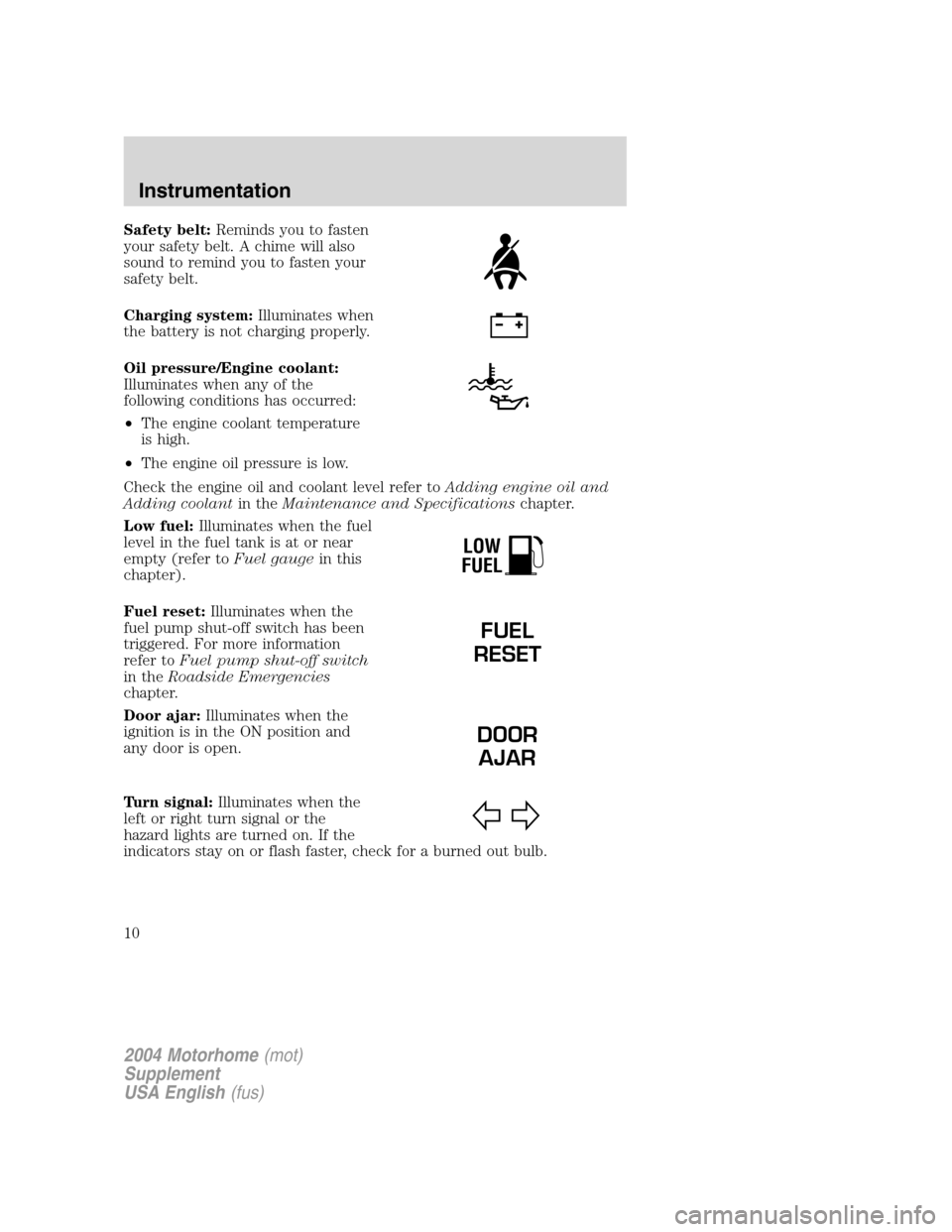
Safety belt:Reminds you to fasten
your safety belt. A chime will also
sound to remind you to fasten your
safety belt.
Charging system:Illuminates when
the battery is not charging properly.
Oil pressure/Engine coolant:
Illuminates when any of the
following conditions has occurred:
•The engine coolant temperature
is high.
•The engine oil pressure is low.
Check the engine oil and coolant level refer toAdding engine oil and
Adding coolantin theMaintenance and Specificationschapter.
Low fuel:Illuminates when the fuel
level in the fuel tank is at or near
empty (refer toFuel gaugein this
chapter).
Fuel reset:Illuminates when the
fuel pump shut-off switch has been
triggered. For more information
refer toFuel pump shut-off switch
in theRoadside Emergencies
chapter.
Door ajar:Illuminates when the
ignition is in the ON position and
any door is open.
Turn signal:Illuminates when the
left or right turn signal or the
hazard lights are turned on. If the
indicators stay on or flash faster, check for a burned out bulb.
LOW
FUEL
FUEL
RESET
DOOR
AJAR
2004 Motorhome(mot)
Supplement
USA English(fus)
Instrumentation
10
Page 13 of 120
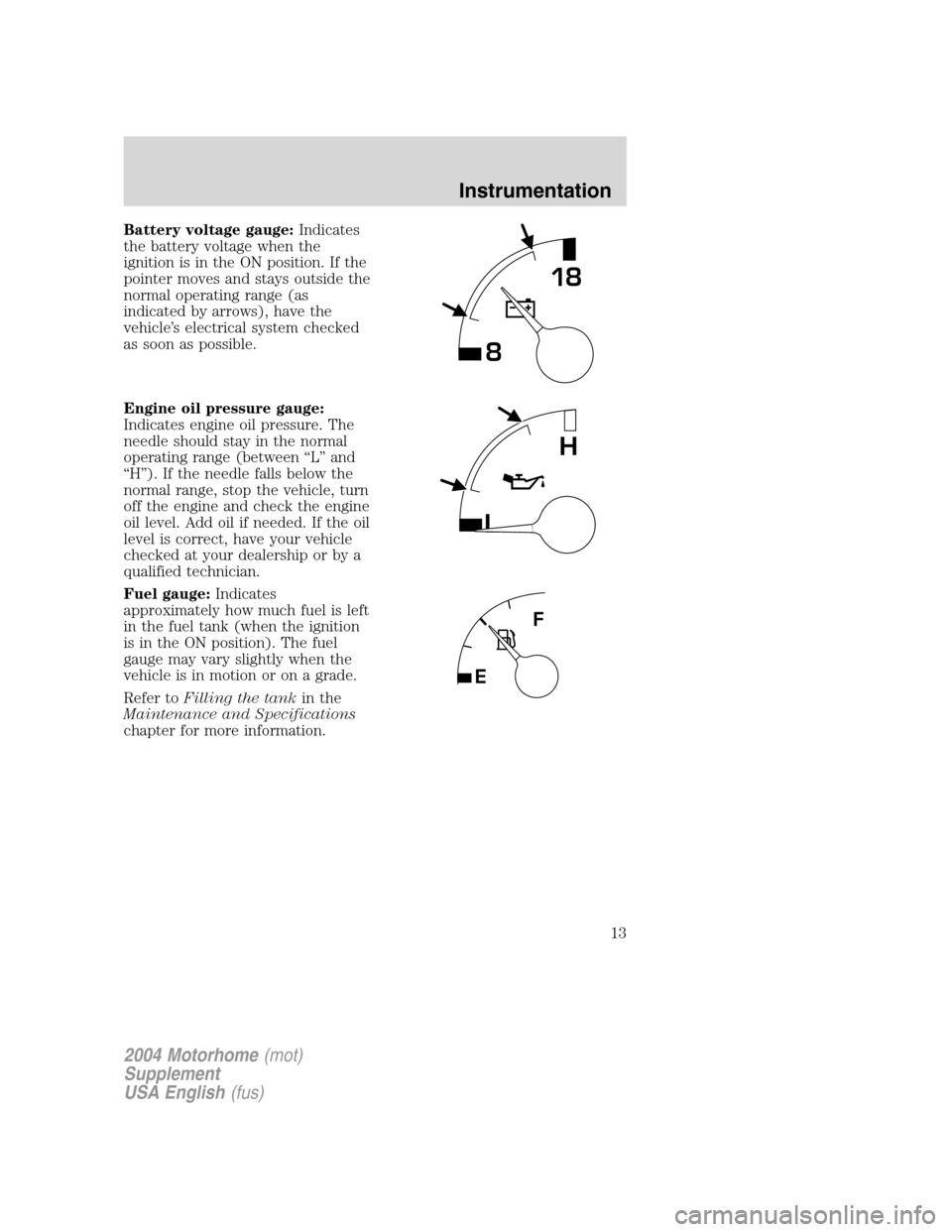
Battery voltage gauge:Indicates
the battery voltage when the
ignition is in the ON position. If the
pointer moves and stays outside the
normal operating range (as
indicated by arrows), have the
vehicle’s electrical system checked
as soon as possible.
Engine oil pressure gauge:
Indicates engine oil pressure. The
needle should stay in the normal
operating range (between“L”and
“H”). If the needle falls below the
normal range, stop the vehicle, turn
off the engine and check the engine
oil level. Add oil if needed. If the oil
level is correct, have your vehicle
checked at your dealership or by a
qualified technician.
Fuel gauge:Indicates
approximately how much fuel is left
in the fuel tank (when the ignition
is in the ON position). The fuel
gauge may vary slightly when the
vehicle is in motion or on a grade.
Refer toFilling the tankin the
Maintenance and Specifications
chapter for more information.
818
L
H
2004 Motorhome(mot)
Supplement
USA English(fus)
Instrumentation
13
Page 42 of 120
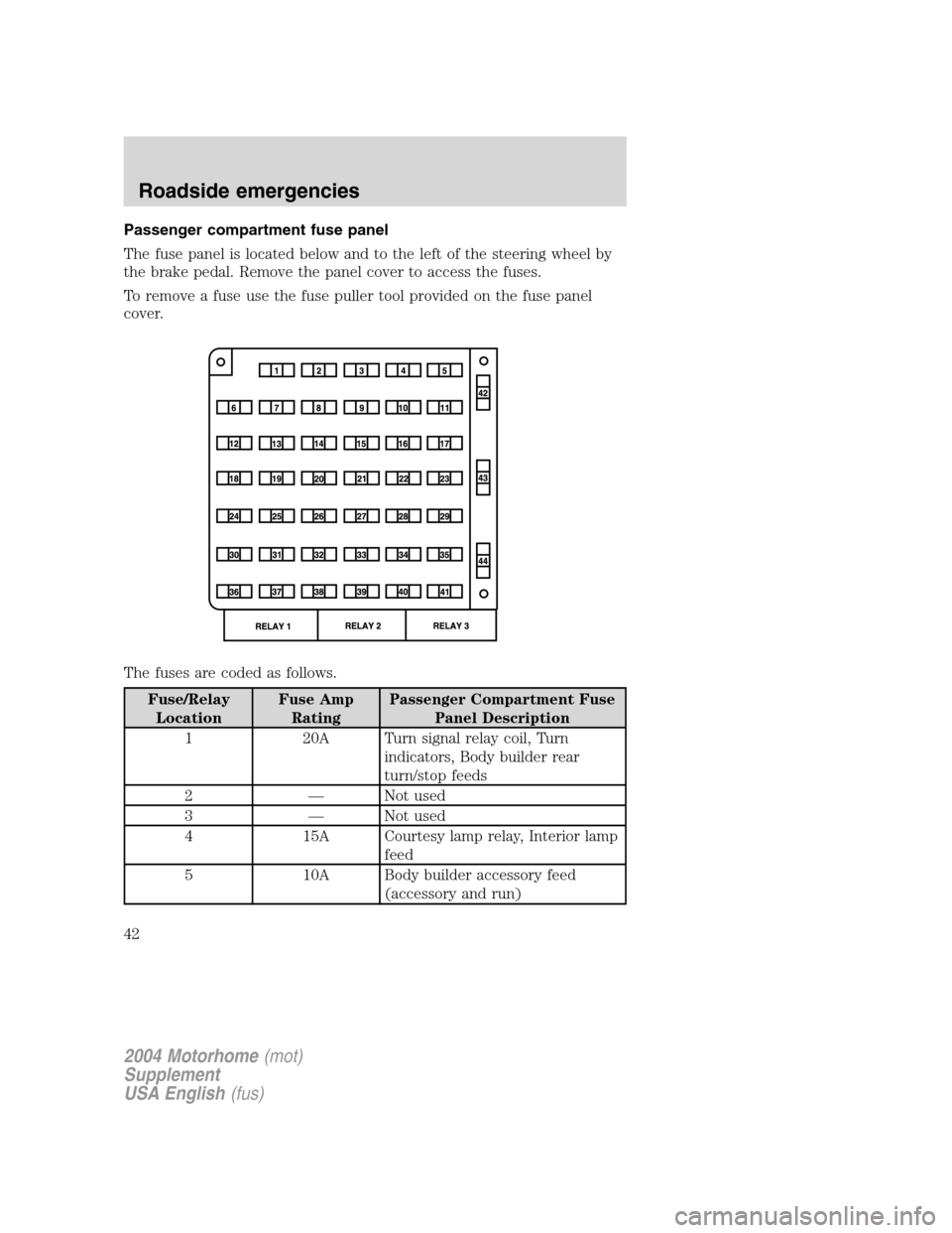
Passenger compartment fuse panel
The fuse panel is located below and to the left of the steering wheel by
the brake pedal. Remove the panel cover to access the fuses.
To remove a fuse use the fuse puller tool provided on the fuse panel
cover.
The fuses are coded as follows.
Fuse/Relay
LocationFuse Amp
RatingPassenger Compartment Fuse
Panel Description
1 20A Turn signal relay coil, Turn
indicators, Body builder rear
turn/stop feeds
2—Not used
3—Not used
4 15A Courtesy lamp relay, Interior lamp
feed
5 10A Body builder accessory feed
(accessory and run)
2004 Motorhome(mot)
Supplement
USA English(fus)
Roadside emergencies
42
Page 43 of 120
Fuse/Relay
LocationFuse Amp
RatingPassenger Compartment Fuse
Panel Description
6 10A Trailer tow left stop/turn feed
7 15A Blower motor relay coil
8—Not used
9 20A Stoplamps: Trailer tow Electric
Brake controller feed, Body
builder rear turn/stop feeds, Body
builder stop lamp feed, Trailer
turn/stop fuse feeds
10 5A Instrument cluster memory,
Power brake assist lamp*
11 30A Wiper/Washer module, Wiper feed
12 10A Trailer tow stop/turn feed
13 10A ABS module
14 10A Warning chime module, Power
brake assist module*, Instrument
cluster power, Instrument cluster
warning lamps, Transmission
control switch
15 15A Left turn signal feed
16 20A Body builder battery (+12V) feed
17 5A Body builder radio feed
18—Not used
19 5A DRL relays
20—Not used
21 15A Right turn signal feed
22—Not used
23—Not used
24—Not used
25 10A Right-hand low beam headlamp
feed
26 10A Speed control module, Brake shift
interlock actuator
2004 Motorhome(mot)
Supplement
USA English(fus)
Roadside emergencies
43
Page 46 of 120
The high-current fuses are coded as follows.
Fuse/Relay
LocationFuse Amp
RatingPower Distribution Box
Description
1 5A* Power brake assist module***
2 10A* A/C system
3 20A* Transmission, Vapor Management
Valve (VMV) solenoid, Heated
exhaust gas oxygen (HEGO)
sensors
4 5A* Powertrain Control Module (PCM)
memory
5 15A* PCM power, Fuel pump relay coil,
Fuel injectors, Mass Air Flow
(MAF) sensor with IAT, A/C
system relay coil
6 20A* Parklamp feeds, Instrument panel
fuse #41, Warning chime module,
Trailer tow running lamp relay
coil, I/P dimmer module
7 15A* Starter relay coil, BB neutral
sense
8 10A* Stoplamp switch (logic): Power
brake assist module***, Speed
control module, PCM, Anti-lock
Brake System (ABS) module,
Brake shift interlock actuator
9 5A* Alternator, Charge indicator
10 20A* Daytime Running Lamps (DRL)
11 30A* Ignition coils, Radio capacitors #1
and #2, PCM relay
12 20A* Trailer tow running lamps feed,
Trailer tow back-up lamps feed, IP
- backup lamp feed
13 30A** Trailer tow electric brake
controller feed
2004 Motorhome(mot)
Supplement
USA English(fus)
Roadside emergencies
46
Page 52 of 120
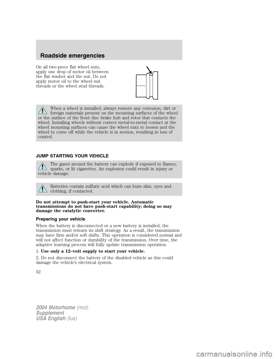
On all two-piece flat wheel nuts,
apply one drop of motor oil between
the flat washer and the nut. Do not
apply motor oil to the wheel nut
threads or the wheel stud threads.
When a wheel is installed, always remove any corrosion, dirt or
foreign materials present on the mounting surfaces of the wheel
or the surface of the front disc brake hub and rotor that contacts the
wheel. Installing wheels without correct metal-to-metal contact at the
wheel mounting surfaces can cause the wheel nuts to loosen and the
wheel to come off while the vehicle is in motion, resulting in loss of
control.
JUMP STARTING YOUR VEHICLE
The gases around the battery can explode if exposed to flames,
sparks, or lit cigarettes. An explosion could result in injury or
vehicle damage.
Batteries contain sulfuric acid which can burn skin, eyes and
clothing, if contacted.
Do not attempt to push-start your vehicle. Automatic
transmissions do not have push-start capability; doing so may
damage the catalytic converter.
Preparing your vehicle
When the battery is disconnected or a new battery is installed, the
transmission must relearn its shift strategy. As a result, the transmission
may have firm and/or soft shifts. This operation is considered normal and
will not affect function or durability of the transmission. Over time, the
adaptive learning process will fully update transmission operation.
1.Use only a 12–volt supply to start your vehicle.
2. Do not disconnect the battery of the disabled vehicle as this could
damage the vehicle’s electrical system.
2004 Motorhome(mot)
Supplement
USA English(fus)
Roadside emergencies
52
Page 68 of 120
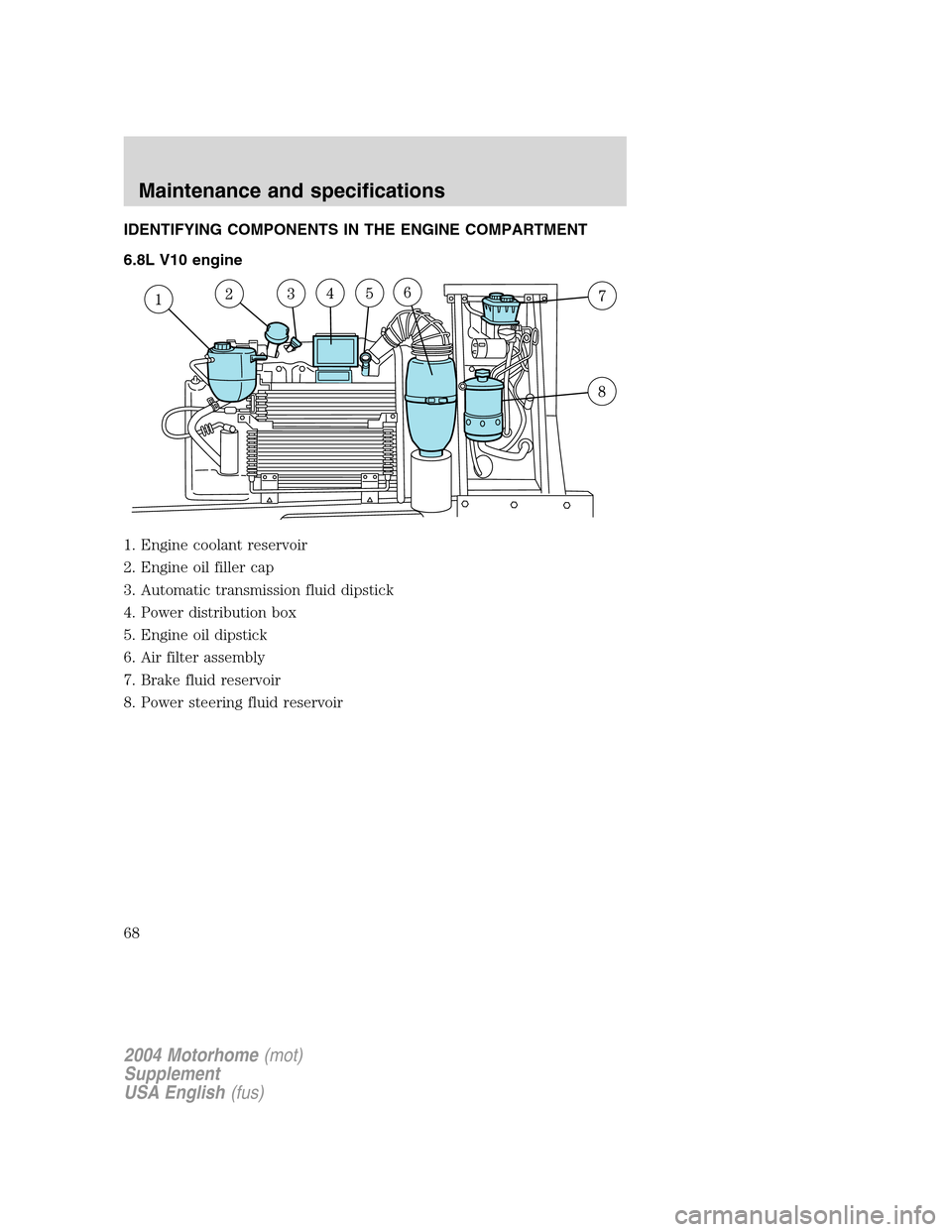
IDENTIFYING COMPONENTS IN THE ENGINE COMPARTMENT
6.8L V10 engine
1. Engine coolant reservoir
2. Engine oil filler cap
3. Automatic transmission fluid dipstick
4. Power distribution box
5. Engine oil dipstick
6. Air filter assembly
7. Brake fluid reservoir
8. Power steering fluid reservoir
2004 Motorhome(mot)
Supplement
USA English(fus)
Maintenance and specifications
68