power steering FORD F SERIES MOTORHOME AND COMMERCIAL CHASSIS 2011 12.G Owners Manual
[x] Cancel search | Manufacturer: FORD, Model Year: 2011, Model line: F SERIES MOTORHOME AND COMMERCIAL CHASSIS, Model: FORD F SERIES MOTORHOME AND COMMERCIAL CHASSIS 2011 12.GPages: 156, PDF Size: 1.21 MB
Page 9 of 156
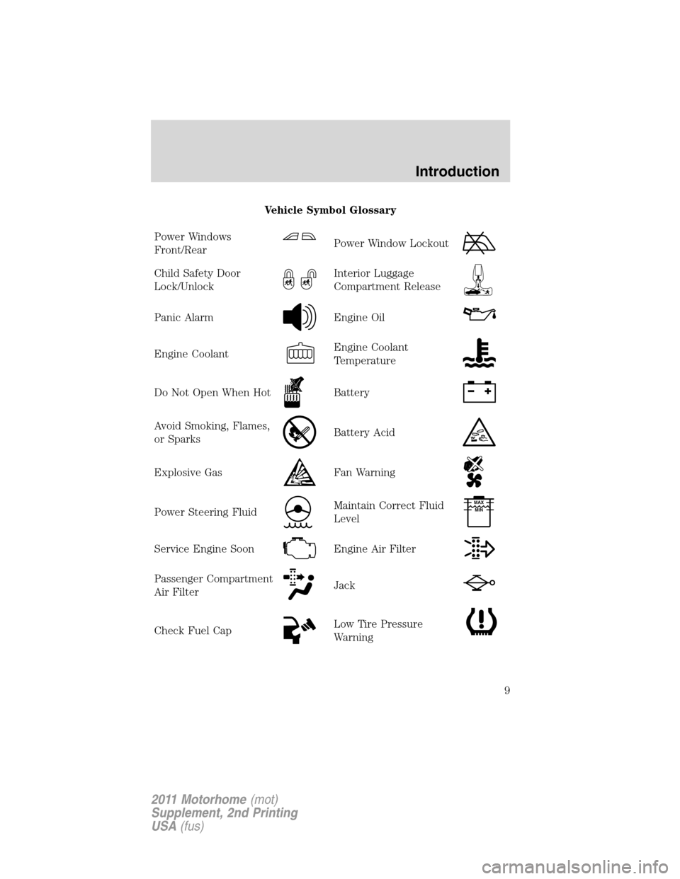
Vehicle Symbol Glossary
Power Windows
Front/Rear
Power Window Lockout
Child Safety Door
Lock/UnlockInterior Luggage
Compartment Release
Panic AlarmEngine Oil
Engine CoolantEngine Coolant
Temperature
Do Not Open When HotBattery
Avoid Smoking, Flames,
or SparksBattery Acid
Explosive GasFan Warning
Power Steering FluidMaintain Correct Fluid
LevelMAX
MIN
Service Engine SoonEngine Air Filter
Passenger Compartment
Air FilterJack
Check Fuel CapLow Tire Pressure
Warning
Introduction
9
2011 Motorhome(mot)
Supplement, 2nd Printing
USA(fus)
Page 33 of 156
U.S. DOT Tire Identification Number (TIN)
Both U.S. and Canada Federal regulations require tire manufacturers to
place standardized information on the sidewall of all tires. This
information identifies and describes the fundamental characteristics of
the tire and also provides a U.S. DOT Tire Identification Number for
safety standard certification and in case of a recall.
This begins with the letters “DOT” and indicates that the tire meets all
federal standards. The next two numbers or letters are the plant code
designating where it was manufactured, the next two are the tire size
code and the last four numbers represent the week and year the tire was
built. For example, the numbers 317 mean the 31st week of 1997. After
2000 the numbers go to four digits. For example, 2501 means the 25th
week of 2001. The numbers in between are identification codes used for
traceability. This information is used to contact customers if a tire defect
requires a recall.
Tire replacement requirements
Your vehicle is equipped with tires designed to provide a safe ride and
handling capability.
WARNING:Only use replacement tires and wheels that are the
same size, load index, speed rating and type (such as P-metric
versus LT-metric or all-season versus all-terrain) as those originally
provided by Ford. The recommended tire and wheel size may be found
on either the Safety Compliance Certification Label or the Tire Label
which is located on the B-Pillar or edge of the driver’s door. If this
information is not found on these labels then you should contact your
authorized dealer as soon as possible. Use of any tire or wheel not
recommended by Ford can affect the safety and performance of your
vehicle, which could result in an increased risk of loss of vehicle
control, vehicle rollover, personal injury and death. Additionally the use
of non-recommended tires and wheels could cause steering,
suspension, axle or transfer case/power transfer unit failure. If you
have questions regarding tire replacement, contact your authorized
dealer as soon as possible.
Tires, Wheels and Loading
33
2011 Motorhome(mot)
Supplement, 2nd Printing
USA(fus)
Page 41 of 156
Information on “T” type tires
“T” type tires have some additional
information beyond those of “P”
type tires; these differences are
described below:
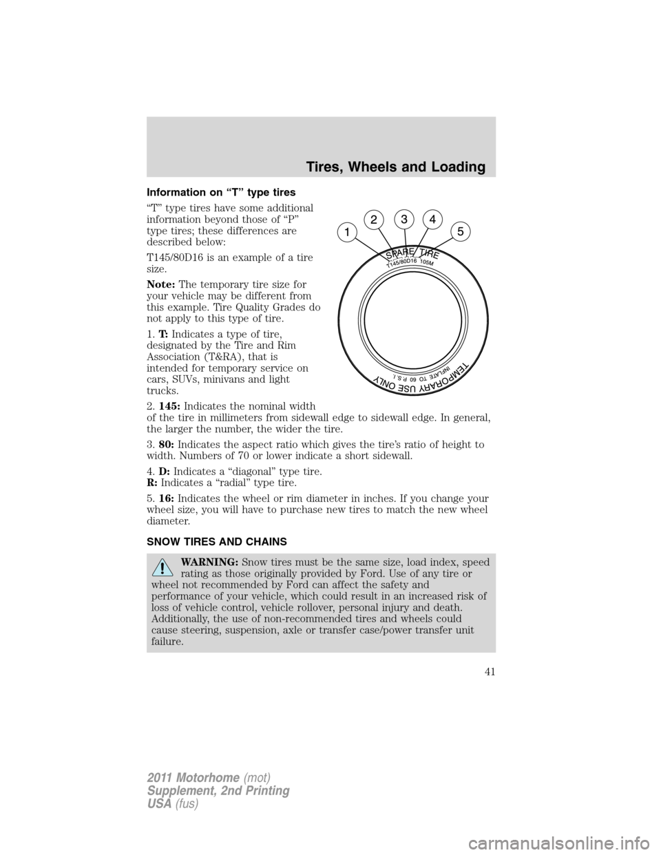
T145/80D16 is an example of a tire
size.
Note:The temporary tire size for
your vehicle may be different from
this example. Tire Quality Grades do
not apply to this type of tire.
1.T:Indicates a type of tire,
designated by the Tire and Rim
Association (T&RA), that is
intended for temporary service on
cars, SUVs, minivans and light
trucks.
2.145:Indicates the nominal width
of the tire in millimeters from sidewall edge to sidewall edge. In general,
the larger the number, the wider the tire.
3.80:Indicates the aspect ratio which gives the tire’s ratio of height to
width. Numbers of 70 or lower indicate a short sidewall.
4.D:Indicates a “diagonal” type tire.
R:Indicates a “radial” type tire.
5.16:Indicates the wheel or rim diameter in inches. If you change your
wheel size, you will have to purchase new tires to match the new wheel
diameter.
SNOW TIRES AND CHAINS
WARNING:Snow tires must be the same size, load index, speed
rating as those originally provided by Ford. Use of any tire or
wheel not recommended by Ford can affect the safety and
performance of your vehicle, which could result in an increased risk of
loss of vehicle control, vehicle rollover, personal injury and death.
Additionally, the use of non-recommended tires and wheels could
cause steering, suspension, axle or transfer case/power transfer unit
failure.
Tires, Wheels and Loading
41
2011 Motorhome(mot)
Supplement, 2nd Printing
USA(fus)
Page 51 of 156
STARTING
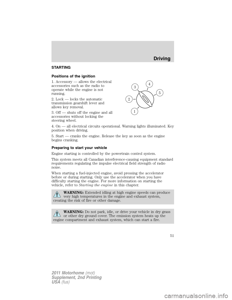
Positions of the ignition
1. Accessory — allows the electrical
accessories such as the radio to
operate while the engine is not
running.
2. Lock — locks the automatic
transmission gearshift lever and
allows key removal.
3. Off — shuts off the engine and all
accessories without locking the
steering wheel.
4. On — all electrical circuits operational. Warning lights illuminated. Key
position when driving.
5. Start — cranks the engine. Release the key as soon as the engine
begins cranking.
Preparing to start your vehicle
Engine starting is controlled by the powertrain control system.
This system meets all Canadian interference-causing equipment standard
requirements regulating the impulse electrical field strength of radio
noise.
When starting a fuel-injected engine, avoid pressing the accelerator
before or during starting. Only use the accelerator when you have
difficulty starting the engine. For more information on starting the
vehicle, refer toStarting the enginein this chapter.
WARNING:Extended idling at high engine speeds can produce
very high temperatures in the engine and exhaust system,
creating the risk of fire or other damage.
WARNING:Do not park, idle, or drive your vehicle in dry grass
or other dry ground cover. The emission system heats up the
engine compartment and exhaust system, which can start a fire.
3
1
2
5
4
Driving
51
2011 Motorhome(mot)
Supplement, 2nd Printing
USA(fus)
Page 55 of 156
Hydraulic brake booster system (Hydroboost or Hydromax)
The Hydroboost and Hydromax systems receive fluid pressure from the
power steering pump to provide power assist during braking.
The Hydromax booster receives backup pressure from the reserve
system electric pump whenever the fluid in the power steering system is
not flowing. When the engine is OFF, the pump will turn on if the brake
pedal is applied, or if the ignition is turned to the ON position.
The sound of the pump operating may be heard by the driver, but this is
a normal characteristic of the system.
The reserve system provides reduced braking power, so the vehicle
should be operated under these conditions with caution, and only to seek
service repair and remove the vehicle from the roadway.
For Hydromax-equipped vehicles operating under normal
conditions,the noise of the fluid flowing through the booster may be
heard whenever the brake is applied. This condition is normal. Vehicle
service is not required.
If braking performance or pedal response becomes very poor, even when
the pedal is strongly pressed, it may indicate the presence of air in the
hydraulic system or leakage of fluid. Stop the vehicle safely as soon as
possible and seek service immediately.
Anti-lock brake system (ABS)
On vehicles equipped with an anti-lock braking system (ABS), a noise
from the hydraulic pump motor and pulsation in the pedal may be
observed during ABS braking events. Pedal pulsation coupled with noise
while braking under panic conditions or on loose gravel, bumps, wet or
snowy roads is normal and indicates proper functioning of the vehicle’s
anti-lock brake system. The ABS performs a self-check after you start
the engine and begin to drive away. A brief mechanical noise may be
heard during this test. This is normal. If a malfunction is found, the ABS
warning light will come on. If the vehicle has continuous vibration or
shudder in the steering wheel while braking, the vehicle should be
inspected by an authorized dealer.
Driving
55
2011 Motorhome(mot)
Supplement, 2nd Printing
USA(fus)
Page 73 of 156
The components are coded as follows:
Relay location Description
1 One touch integrated start (ATO diode)
2 Not used
3 Not used
4 Daytime running lamps (DRL) power relay
5 Not used
6 Reverse lamps relay
7 Starter ground relay
8 Trailer tow parking lamps relay
CHANGING THE TIRES
If you get a flat tire while driving, do not apply the brake heavily.
Instead, gradually decrease your speed. Hold the steering wheel firmly
and slowly move to a safe place on the side of the road.
Dissimilar spare tire/wheel information
WARNING:Failure to follow these guidelines could result in an
increased risk of loss of vehicle control, injury or death.
If you have a dissimilar spare tire/wheel, then it is intended for
temporary use only. This means that if you need to use it, you should
replace it as soon as possible with a road tire/wheel that is the same size
and type as the road tires and wheels that were originally provided by
Ford. If the dissimilar spare tire or wheel is damaged, it should be
replaced rather than repaired.
A dissimilar spare tire/wheel is defined as a spare tire and/or wheel that
is different in brand, size or appearance from the road tires and wheels
and can be one of three types:
1.T-type mini-spare:This spare tire begins with the letter “T” for tire
size and may have “Temporary Use Only” molded in the sidewall
2.Full-size dissimilar spare with label on wheel:This spare tire has
a label on the wheel that states: “THIS TIRE AND WHEEL FOR
TEMPORARY USE ONLY”
Roadside Emergencies
73
2011 Motorhome(mot)
Supplement, 2nd Printing
USA(fus)
Page 92 of 156
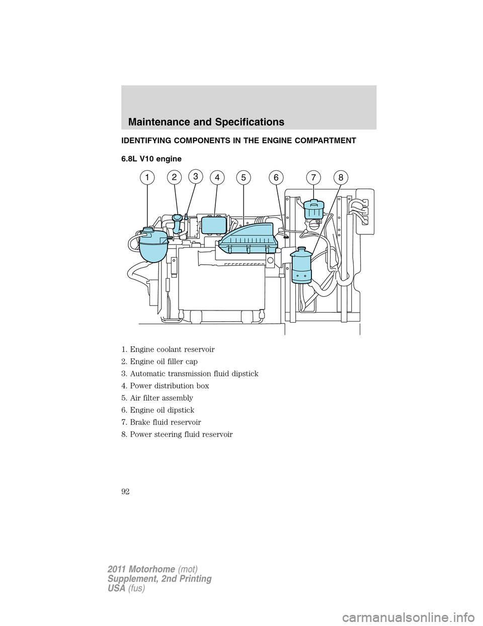
IDENTIFYING COMPONENTS IN THE ENGINE COMPARTMENT
6.8L V10 engine
1. Engine coolant reservoir
2. Engine oil filler cap
3. Automatic transmission fluid dipstick
4. Power distribution box
5. Air filter assembly
6. Engine oil dipstick
7. Brake fluid reservoir
8. Power steering fluid reservoir
12345678
Maintenance and Specifications
92
2011 Motorhome(mot)
Supplement, 2nd Printing
USA(fus)
Page 93 of 156
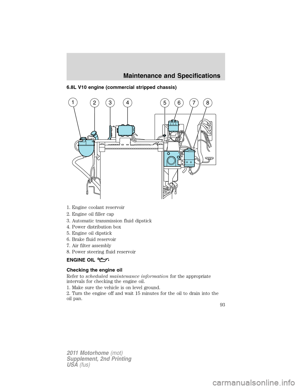
6.8L V10 engine (commercial stripped chassis)
1. Engine coolant reservoir
2. Engine oil filler cap
3. Automatic transmission fluid dipstick
4. Power distribution box
5. Engine oil dipstick
6. Brake fluid reservoir
7. Air filter assembly
8. Power steering fluid reservoir
ENGINE OIL
Checking the engine oil
Refer toscheduled maintenance informationfor the appropriate
intervals for checking the engine oil.
1. Make sure the vehicle is on level ground.
2. Turn the engine off and wait 15 minutes for the oil to drain into the
oil pan.
13425786
Maintenance and Specifications
93
2011 Motorhome(mot)
Supplement, 2nd Printing
USA(fus)
Page 103 of 156
•Overheat messages will appear in the message center. SeeWarning
lights and chimesandMessage centerin theInstrument Cluster
chapter for more information.
•The service engine soon
indicator light will illuminate.
If the engine reaches a preset over-temperature condition, the engine
will automatically switch to alternating cylinder operation. Each disabled
cylinder acts as an air pump and cools the engine.
When this occurs, the vehicle will still operate. However:
•the engine power will be limited, and
•the air conditioning system will be disabled.
Continued operation will increase the engine temperature and the engine
will completely shut down, causing steering and braking effort to
increase.
Once the engine temperature cools, the engine can be re-started. Take
your vehicle to an authorized dealer as soon as possible to minimize
engine damage.
When fail-safe mode is activated
You have limited engine power when in the fail-safe mode, so drive the
vehicle with caution. The vehicle will not be able to maintain high-speed
operation and the engine will run rough. Remember that the engine is
capable of completely shutting down automatically to prevent engine
damage, therefore:
1. Pull off the road as soon as safely possible and turn off the engine.
2. Arrange for the vehicle to be taken to an authorized dealer.
3. If this is not possible, wait a short period for the engine to cool.
4. Check the coolant level and replenish if low.
WARNING:Fail-safe mode is for use during emergencies only.
Operate the vehicle in fail-safe mode only as long as necessary to
bring the vehicle to rest in a safe location and seek immediate repairs.
When in fail-safe mode, the vehicle will have limited power, will not be
able to maintain high-speed operation, and may completely shut down
without warning, potentially losing engine power, power steering assist,
and power brake assist, which may increase the possibility of a crash
resulting in serious injury.
Maintenance and Specifications
103
2011 Motorhome(mot)
Supplement, 2nd Printing
USA(fus)
Page 114 of 156
POWER STEERING FLUID
Check the power steering fluid.
Refer toscheduled maintenance
information.
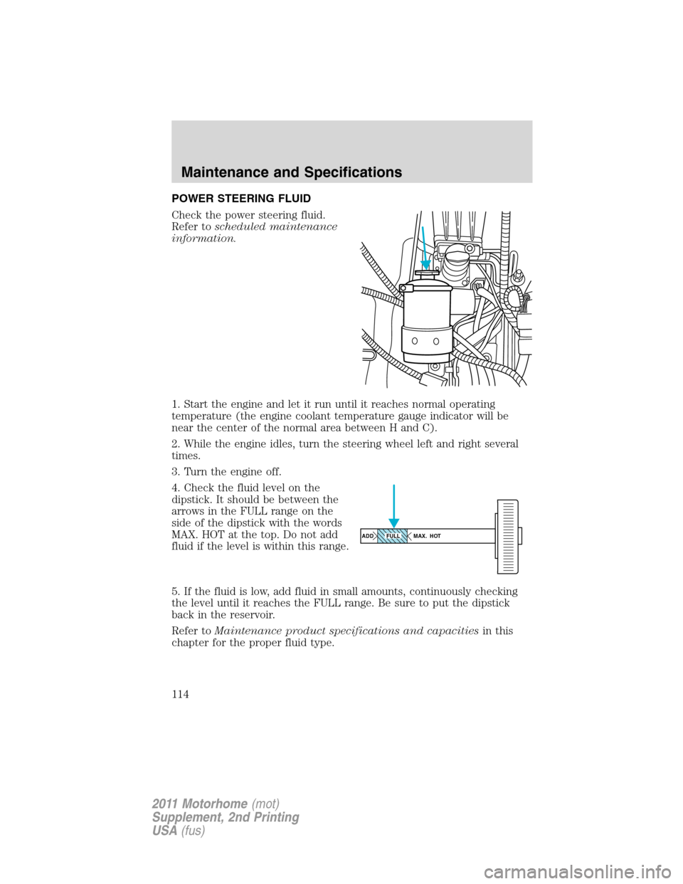
1. Start the engine and let it run until it reaches normal operating
temperature (the engine coolant temperature gauge indicator will be
near the center of the normal area between H and C).
2. While the engine idles, turn the steering wheel left and right several
times.
3. Turn the engine off.
4. Check the fluid level on the
dipstick. It should be between the
arrows in the FULL range on the
side of the dipstick with the words
MAX. HOT at the top. Do not add
fluid if the level is within this range.
5. If the fluid is low, add fluid in small amounts, continuously checking
the level until it reaches the FULL range. Be sure to put the dipstick
back in the reservoir.
Refer toMaintenance product specifications and capacitiesin this
chapter for the proper fluid type.
ADD MAX. HOTFULL
Maintenance and Specifications
114
2011 Motorhome(mot)
Supplement, 2nd Printing
USA(fus)