lock FORD F150 2003 10.G Repair Manual
[x] Cancel search | Manufacturer: FORD, Model Year: 2003, Model line: F150, Model: FORD F150 2003 10.GPages: 280, PDF Size: 4.2 MB
Page 174 of 280
GETTING ROADSIDE ASSISTANCE
To fully assist you should you have a vehicle concern, Ford Motor
Company offers a complimentary roadside assistance program. This
program is separate from the New Vehicle Limited Warranty. The service
is available:
•24–hours, seven days a week
•
for the New Vehicle Limited Warranty period of three years or 60,000 km
(36,000 miles), whichever occurs first on Ford and Mercury vehicles,
and four years or 80,000 km (50,000 miles) on Lincoln vehicles.
Roadside assistance will cover:
•changing a flat tire
•jump-starts
•lock-out assistance
•limited fuel delivery
•towing of your disabled vehicle to the nearest Ford Motor Company
dealership, or your selling dealer if within 56.3 km (35 miles) of the
nearest Ford Motor Company dealership (one tow per disablement).
Even non-warranty related tows, like accidents or getting stuck in the
mud or snow, are covered (some exclusions apply, such as impound
towing or repossession).
Canadian customers refer to your Owner Information Guide for
information on:
•coverage period
•exact fuel amounts
•towing of your disabled vehicle
•emergency travel expense reimbursement
•travel planning benefits
USING ROADSIDE ASSISTANCE
Complete the roadside assistance identification card and place it in your
wallet for quick reference. In the United States, this card is found in the
Owner Guide portfolio in the glove compartment in Ford vehicles and is
mailed to you if you own a Mercury or Lincoln. In Canada, the card is
found in the Owner Information Guide in the glove compartment.
U.S. Ford or Mercury vehicle customers who require roadside assistance,
call 1–800–241–3673; Lincoln vehicle customers call 1–800–521–4140.
Roadside Emergencies
174
Page 178 of 280
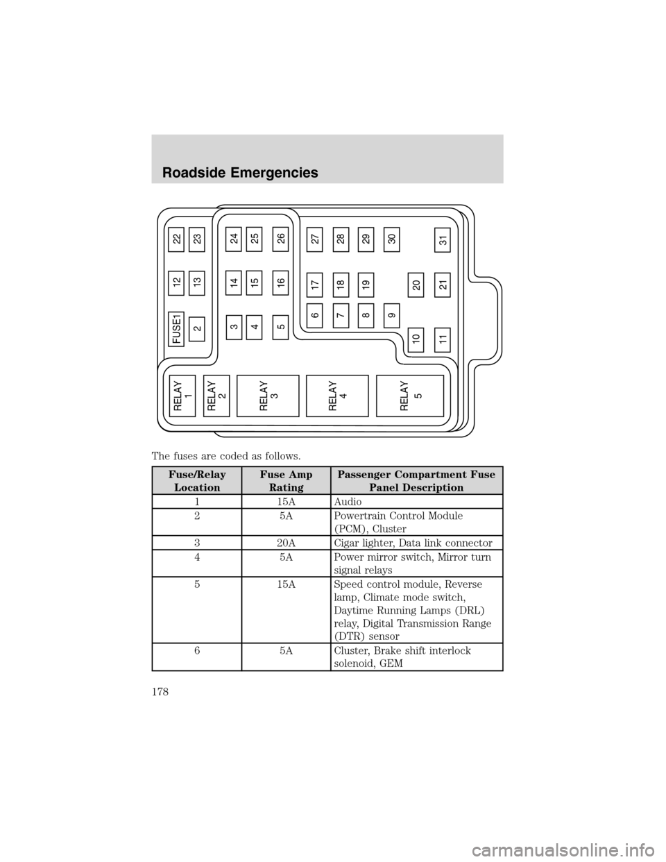
The fuses are coded as follows.
Fuse/Relay
LocationFuse Amp
RatingPassenger Compartment Fuse
Panel Description
1 15A Audio
2 5A Powertrain Control Module
(PCM), Cluster
3 20A Cigar lighter, Data link connector
4 5A Power mirror switch, Mirror turn
signal relays
5 15A Speed control module, Reverse
lamp, Climate mode switch,
Daytime Running Lamps (DRL)
relay, Digital Transmission Range
(DTR) sensor
6 5A Cluster, Brake shift interlock
solenoid, GEM
FUSE1 12 22
21323
617 27
718 28
819 29
930
20
31 21 11 10
RELAY
5 RELAY
4 RELAY
3 RELAY
2 RELAY
1
31424
41525
51626
Roadside Emergencies
178
Page 179 of 280
Fuse/Relay
LocationFuse Amp
RatingPassenger Compartment Fuse
Panel Description
7—Not used
8 5A Radio, Remote entry module,
GEM, In-vehicle entertainment
system (SuperCrew only)
9—Not used
10—Not used
11 30A Front washer pump relay, Wiper
run/park relay, Wiper HI/LO relay,
Windshield wiper motor
12—Not used
13 20A Stop lamp switch (Lamps),
Turn/Hazard flasher
14 15A Battery saver relay, Interior lamp
relay
15 5A Stop lamp switch (speed control,
brake shift interlock), GEM, Rear
Anti-lock Brake System (RABS)
module
16 20A Headlamps (hi beams), Cluster
(hi beam indicator)
17—Not used
18 5A Instrument illumination (dimmer
switch power)
19—Not used
20 5A Audio, GEM, PCM, Transmission
range sensor
21 15A DTR sensor, Clutch switch,
Starter relay, I/P fuse 20
22 10A Air bag module, Passenger air bag
deactivation module
Roadside Emergencies
179
Page 180 of 280
Fuse/Relay
LocationFuse Amp
RatingPassenger Compartment Fuse
Panel Description
23 10A Trailer tow battery Charge relay,
Turn/Hazard flasher, 4x4
solenoids, 4x4 relays, Overhead
console, 4–Wheel Anti-lock Brake
System (4WABS) module, EC
mirror, Heated seats
24 10A Function selector switch assembly
25 10A Heated mirrors
26 10A Right-hand low beam headlamp
27 5A Foglamp relay and foglamp
indicator, Main light switch
(upstream)
28 10A Left-hand low beam headlamp
29 5A Autolamp module, Transmission
overdrive control switch, Central
security module, Beltminder
30 30A Passive Anti-theft transceiver,
Cluster, Ignition coils, PCM relay,
Coil on plugs, Radio noise
capacitor, ECC diode
31—Not used
Relay 1—Interior lamp relay
Relay 2—Battery saver relay
Relay 3—Not used
Relay 4—One-touch down window relay
Relay 5—Accessory delay relay
Power distribution box
The power distribution box is located in the engine compartment. The
power distribution box contains high-current fuses that protect your
vehicle’s main electrical systems from overloads.
Always disconnect the battery before servicing high current
fuses.
Roadside Emergencies
180
Page 182 of 280
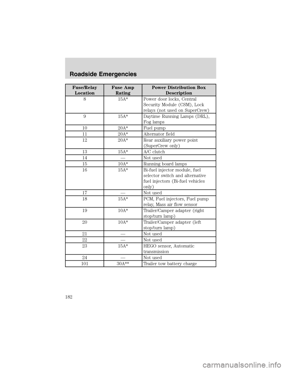
Fuse/Relay
LocationFuse Amp
RatingPower Distribution Box
Description
8 15A* Power door locks, Central
Security Module (CSM), Lock
relays (not used on SuperCrew)
9 15A* Daytime Running Lamps (DRL),
Fog lamps
10 20A* Fuel pump
11 20A* Alternator field
12 20A* Rear auxiliary power point
(SuperCrew only)
13 15A* A/C clutch
14—Not used
15 10A* Running board lamps
16 15A* Bi-fuel injector module, fuel
selector switch and alternative
fuel injectors (Bi-fuel vehicles
only)
17—Not used
18 15A* PCM, Fuel injectors, Fuel pump
relay, Mass air flow sensor
19 10A* Trailer/Camper adapter (right
stop/turn lamp)
20 10A* Trailer/Camper adapter (left
stop/turn lamp)
21—Not used
22—Not used
23 15A* HEGO sensor, Automatic
transmission
24—Not used
101 30A** Trailer tow battery charge
Roadside Emergencies
182
Page 183 of 280
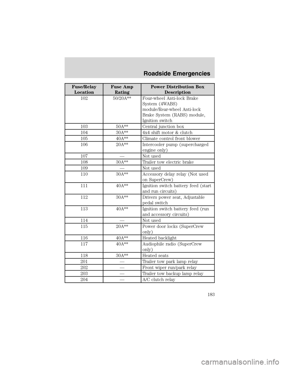
Fuse/Relay
LocationFuse Amp
RatingPower Distribution Box
Description
102 50/20A** Four-wheel Anti-lock Brake
System (4WABS)
module/Rear-wheel Anti-lock
Brake System (RABS) module,
Ignition switch
103 50A** Central junction box
104 30A** 4x4 shift motor & clutch
105 40A** Climate control front blower
106 20A** Intercooler pump (supercharged
engine only)
107—Not used
108 30A** Trailer tow electric brake
109—Not used
110 30A** Accessory delay relay (Not used
on SuperCrew)
111 40A** Ignition switch battery feed (start
and run circuits)
112 30A** Drivers power seat, Adjustable
pedal switch
113 40A** Ignition switch battery feed (run
and accessory circuits)
114—Not used
115 20A** Power door locks (SuperCrew
only)
116 40A** Heated backlight
117 40A** Audiophile radio (SuperCrew
only)
118 30A** Heated seats
201—Trailer tow park lamp relay
202—Front wiper run/park relay
203—Trailer tow backup lamp relay
204—A/C clutch relay
Roadside Emergencies
183
Page 186 of 280
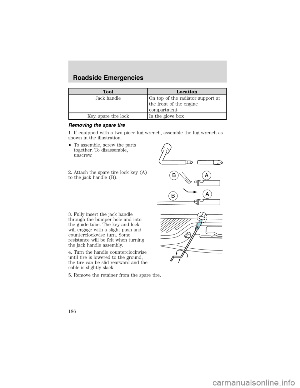
Tool Location
Jack handle On top of the radiator support at
the front of the engine
compartment
Key, spare tire lock In the glove box
Removing the spare tire
1. If equipped with a two piece lug wrench, assemble the lug wrench as
shown in the illustration.
•To assemble, screw the parts
together. To disassemble,
unscrew.
2. Attach the spare tire lock key (A)
to the jack handle (B).
3. Fully insert the jack handle
through the bumper hole and into
the guide tube. The key and lock
will engage with a slight push and
counterclockwise turn. Some
resistance will be felt when turning
the jack handle assembly.
4. Turn the handle counterclockwise
until tire is lowered to the ground,
the tire can be slid rearward and the
cable is slightly slack.
5. Remove the retainer from the spare tire.
Roadside Emergencies
186
Page 187 of 280
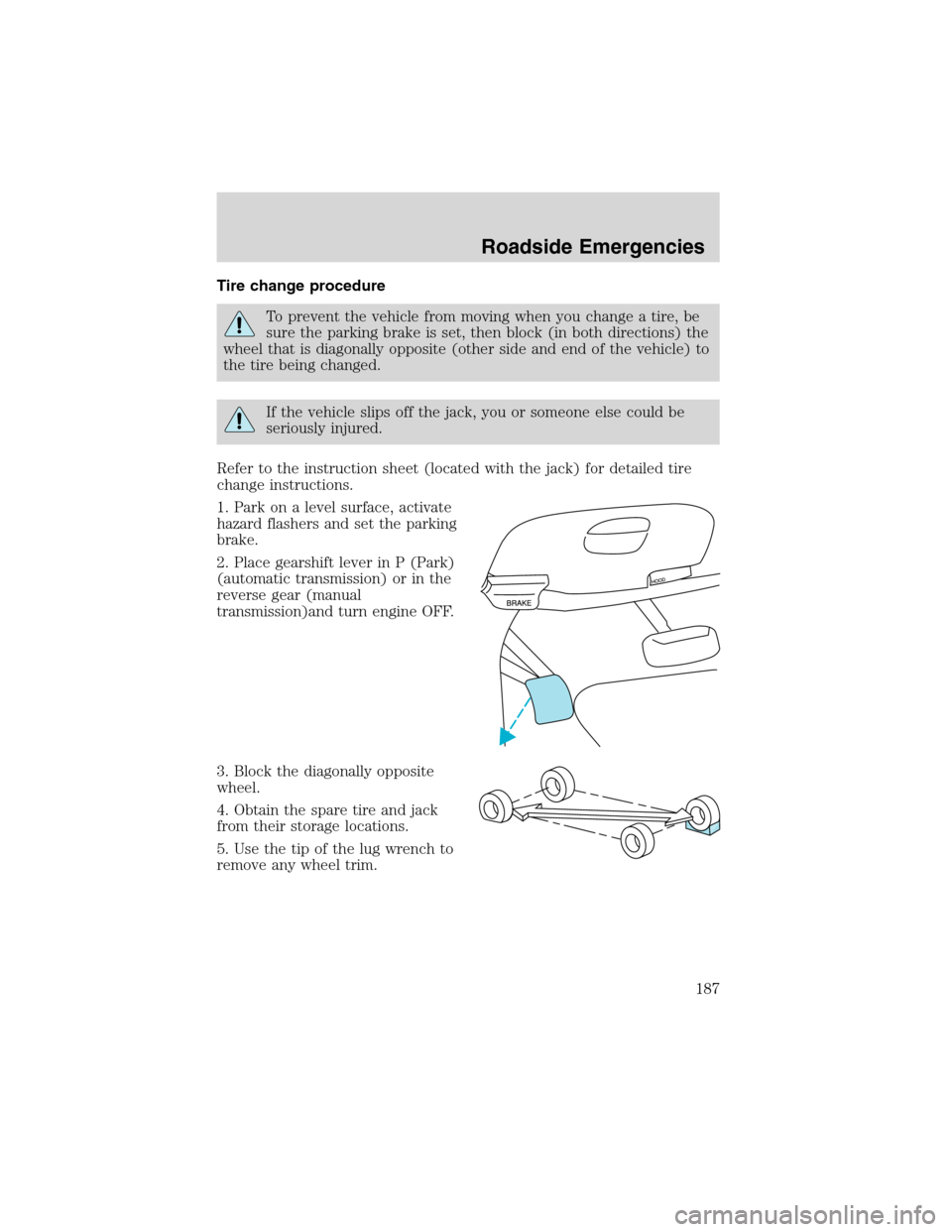
Tire change procedure
To prevent the vehicle from moving when you change a tire, be
sure the parking brake is set, then block (in both directions) the
wheel that is diagonally opposite (other side and end of the vehicle) to
the tire being changed.
If the vehicle slips off the jack, you or someone else could be
seriously injured.
Refer to the instruction sheet (located with the jack) for detailed tire
change instructions.
1. Park on a level surface, activate
hazard flashers and set the parking
brake.
2. Place gearshift lever in P (Park)
(automatic transmission) or in the
reverse gear (manual
transmission)and turn engine OFF.
3. Block the diagonally opposite
wheel.
4. Obtain the spare tire and jack
from their storage locations.
5. Use the tip of the lug wrench to
remove any wheel trim.
Roadside Emergencies
187
Page 188 of 280
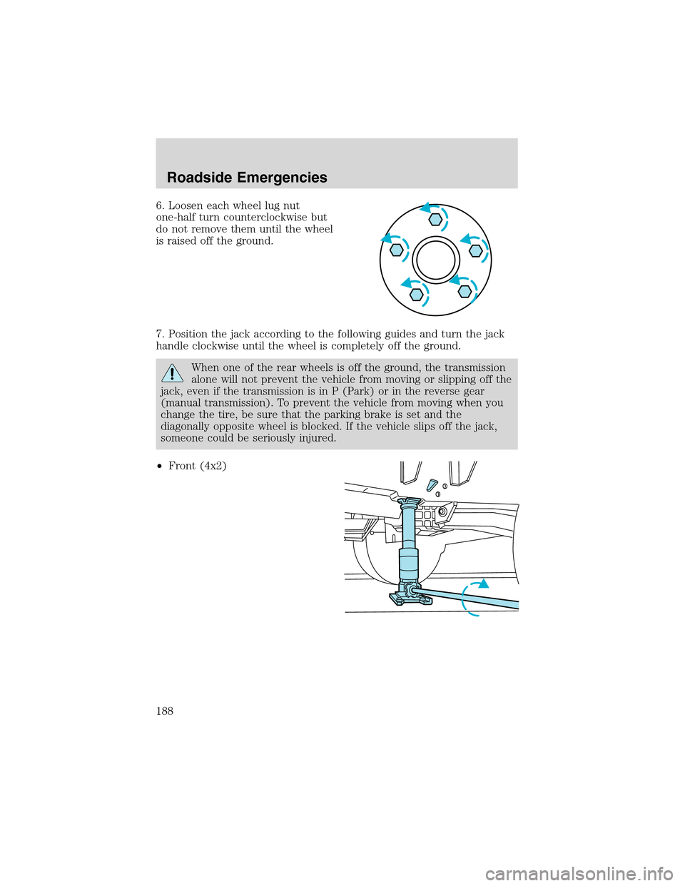
6. Loosen each wheel lug nut
one-half turn counterclockwise but
do not remove them until the wheel
is raised off the ground.
7. Position the jack according to the following guides and turn the jack
handle clockwise until the wheel is completely off the ground.
When one of the rear wheels is off the ground, the transmission
alone will not prevent the vehicle from moving or slipping off the
jack, even if the transmission is in P (Park) or in the reverse gear
(manual transmission). To prevent the vehicle from moving when you
change the tire, be sure that the parking brake is set and the
diagonally opposite wheel is blocked. If the vehicle slips off the jack,
someone could be seriously injured.
•Front (4x2)
Roadside Emergencies
188
Page 189 of 280
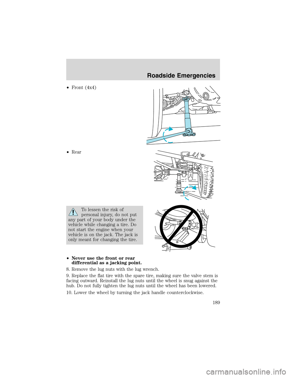
•Front (4x4)
•Rear
To lessen the risk of
personal injury, do not put
any part of your body under the
vehicle while changing a tire. Do
not start the engine when your
vehicle is on the jack. The jack is
only meant for changing the tire.
•Never use the front or rear
differential as a jacking point.
8. Remove the lug nuts with the lug wrench.
9. Replace the flat tire with the spare tire, making sure the valve stem is
facing outward. Reinstall the lug nuts until the wheel is snug against the
hub. Do not fully tighten the lug nuts until the wheel has been lowered.
10. Lower the wheel by turning the jack handle counterclockwise.
Roadside Emergencies
189