FORD F150 2011 12.G Owners Manual
Manufacturer: FORD, Model Year: 2011, Model line: F150, Model: FORD F150 2011 12.GPages: 461, PDF Size: 3.1 MB
Page 121 of 461
Tailgate removal
Your tailgate is removable to allow more room for loading.
WARNING:Always properly secure cargo to prevent shifting
cargo or cargo falling from vehicle, which could result in
compromised vehicle stability and serious personal injury to vehicle
occupants or others.
Note:If equipped with a rearview camera system, do Steps 1 through 3
before removing the tailgate.
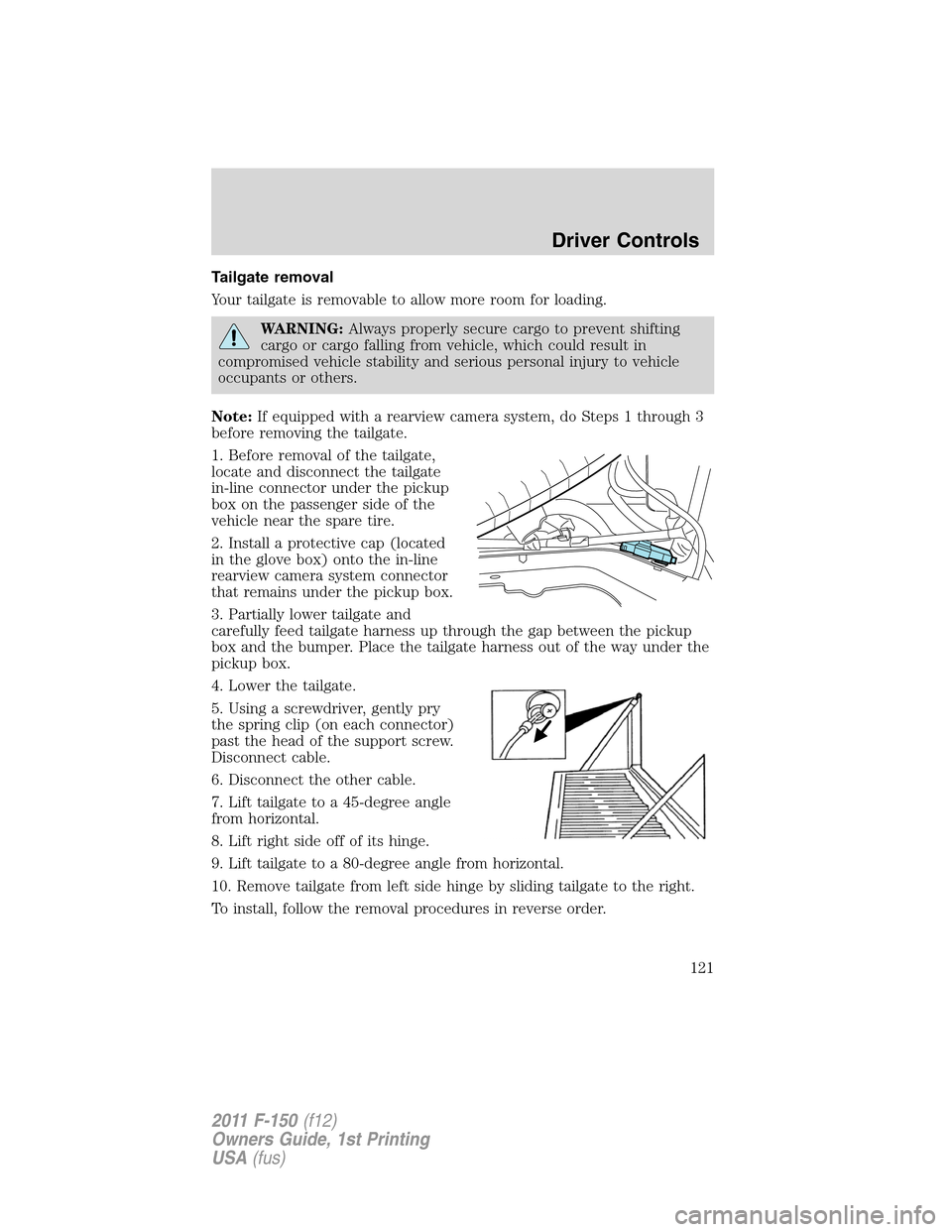
1. Before removal of the tailgate,
locate and disconnect the tailgate
in-line connector under the pickup
box on the passenger side of the
vehicle near the spare tire.
2. Install a protective cap (located
in the glove box) onto the in-line
rearview camera system connector
that remains under the pickup box.
3. Partially lower tailgate and
carefully feed tailgate harness up through the gap between the pickup
box and the bumper. Place the tailgate harness out of the way under the
pickup box.
4. Lower the tailgate.
5. Using a screwdriver, gently pry
the spring clip (on each connector)
past the head of the support screw.
Disconnect cable.
6. Disconnect the other cable.
7. Lift tailgate to a 45-degree angle
from horizontal.
8. Lift right side off of its hinge.
9. Lift tailgate to a 80-degree angle from horizontal.
10. Remove tailgate from left side hinge by sliding tailgate to the right.
To install, follow the removal procedures in reverse order.
Driver Controls
121
2011 F-150(f12)
Owners Guide, 1st Printing
USA(fus)
Page 122 of 461
Tailgate step (if equipped)
Your vehicle may be equipped with a feature that allows easier entry into
the truck bed. To open the tailgate step:
1. Flip down the tailgate.
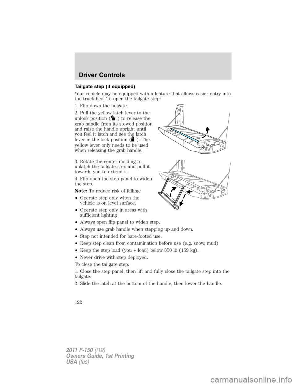
2. Pull the yellow latch lever to the
unlock position (
) to release the
grab handle from its stowed position
and raise the handle upright until
you feel it latch and see the latch
lever in the lock position (
). The
yellow lever only needs to be used
when releasing the grab handle.
3. Rotate the center molding to
unlatch the tailgate step and pull it
towards you to extend it.
4. Flip open the step panel to widen
the step.
Note:To reduce risk of falling:
•Operate step only when the
vehicle is on level surface.
•Operate step only in areas with
sufficient lighting
•Always open flip panel to widen step.
•Always use grab handle when stepping up and down.
•Step not intended for bare-footed use.
•Keep step clean from contamination before use (e.g. snow, mud)
•Keep the step load (you + load) below 350 lb (159 kg).
•Never drive with step deployed.
To close the tailgate step:
1. Close the step panel, then lift and fully close the tailgate step into the
tailgate.
2. Slide the latch at the bottom of the handle, then lower the handle.
Driver Controls
122
2011 F-150(f12)
Owners Guide, 1st Printing
USA(fus)
Page 123 of 461
Note:
•Fully close and latch the tailgate step before moving the vehicle.
•Never drive with the step or grab handle deployed.
•Replace slip resistance tape (serviceable item) if worn out.
•Replace handle molding (serviceable item) if damaged.
•Do not tow with grab handle or step frame.
Box side step (if equipped)
Your vehicle may be equipped with a box side step that allows easier
access to the truck bed.
Note:Do not drive vehicle with box side step(s) in the deployed
position.
Note:The box side step load carrying capability (1 person + cargo) is
500 lb (227 kg). Do not exceed 500 lb (227 kg).
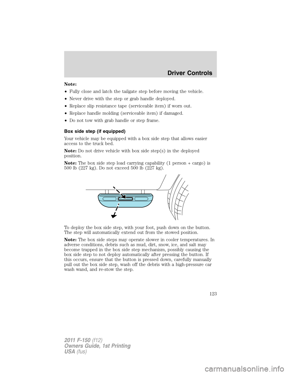
To deploy the box side step, with your foot, push down on the button.
The step will automatically extend out from the stowed position.
Note:The box side steps may operate slower in cooler temperatures. In
adverse conditions, debris such as mud, dirt, snow, ice, and salt may
become trapped in the box side step mechanism, possibly causing the
box side step to not deploy automatically after pressing the button. If
this occurs, ensure that the button is pressed down, carefully manually
pull out the box side step, wash off the debris with a high-pressure car
wash wand, and re-stow the step.
Driver Controls
123
2011 F-150(f12)
Owners Guide, 1st Printing
USA(fus)
Page 124 of 461
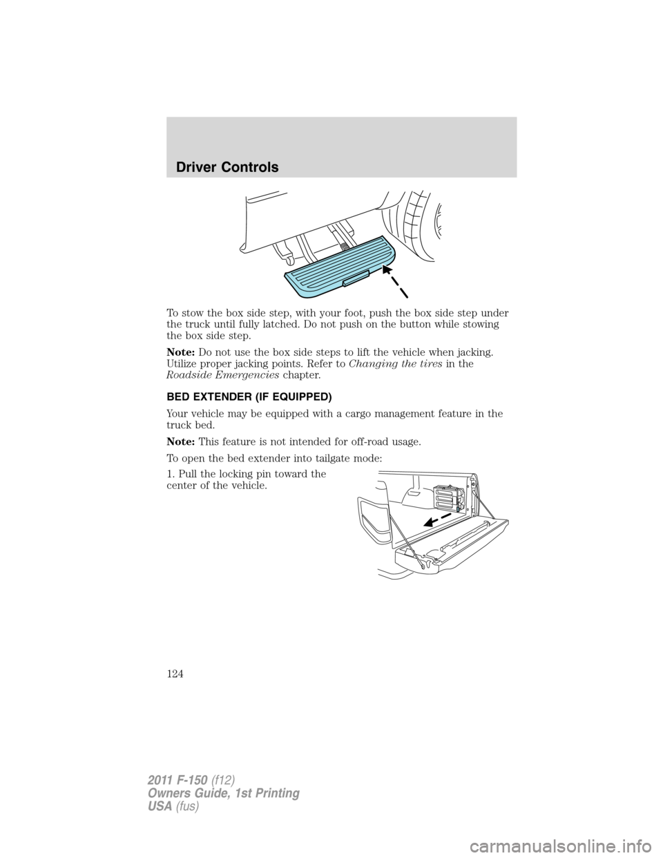
To stow the box side step, with your foot, push the box side step under
the truck until fully latched. Do not push on the button while stowing
the box side step.
Note:Do not use the box side steps to lift the vehicle when jacking.
Utilize proper jacking points. Refer toChanging the tiresin the
Roadside Emergencieschapter.
BED EXTENDER (IF EQUIPPED)
Your vehicle may be equipped with a cargo management feature in the
truck bed.
Note:This feature is not intended for off-road usage.
To open the bed extender into tailgate mode:
1. Pull the locking pin toward the
center of the vehicle.
Driver Controls
124
2011 F-150(f12)
Owners Guide, 1st Printing
USA(fus)
Page 125 of 461
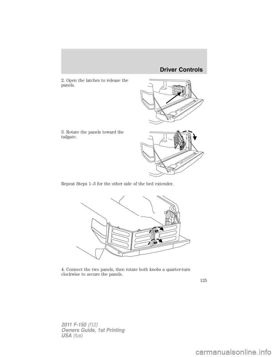
2. Open the latches to release the
panels.
3. Rotate the panels toward the
tailgate.
Repeat Steps 1–3 for the other side of the bed extender.
4. Connect the two panels, then rotate both knobs a quarter-turn
clockwise to secure the panels.
Driver Controls
125
2011 F-150(f12)
Owners Guide, 1st Printing
USA(fus)
Page 126 of 461
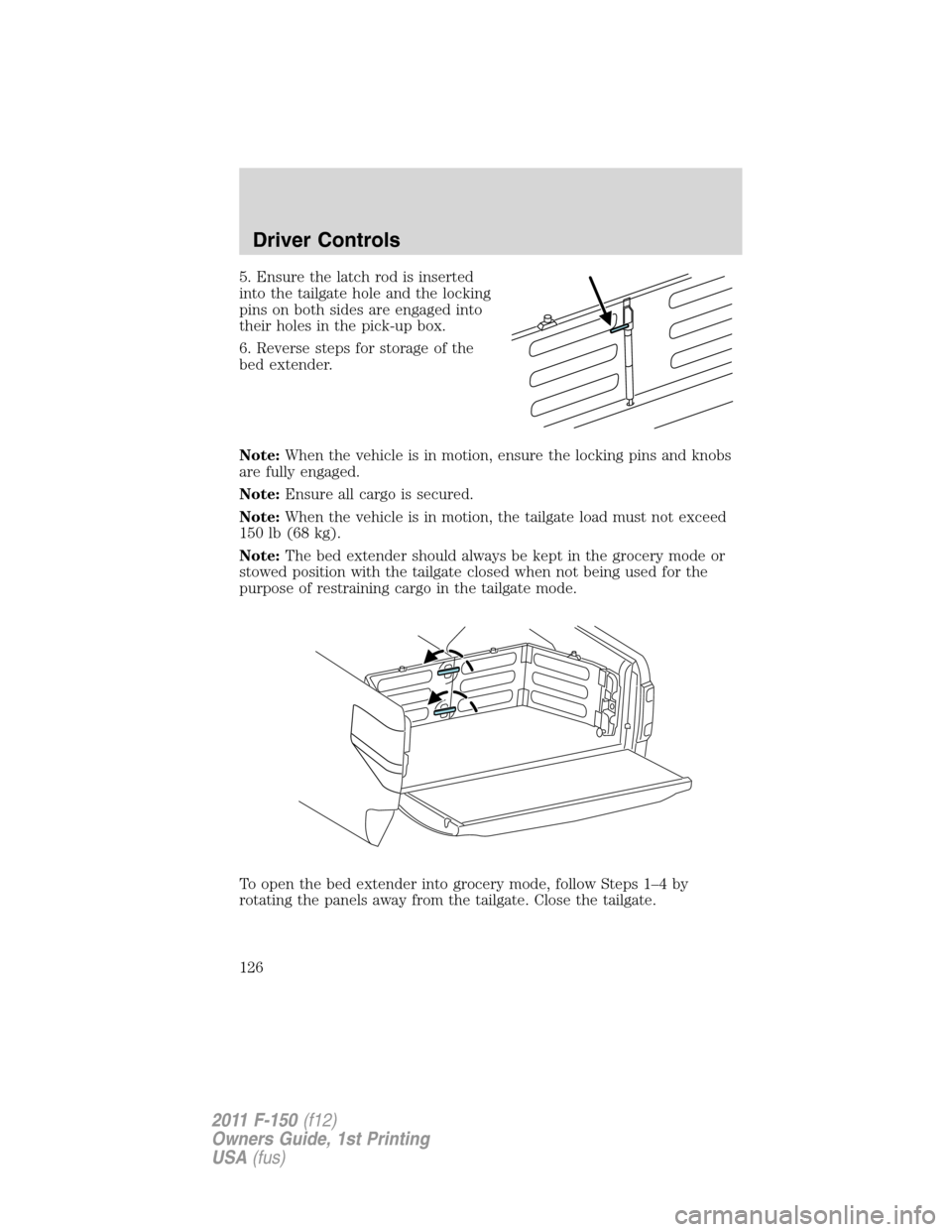
5. Ensure the latch rod is inserted
into the tailgate hole and the locking
pins on both sides are engaged into
their holes in the pick-up box.
6. Reverse steps for storage of the
bed extender.
Note:When the vehicle is in motion, ensure the locking pins and knobs
are fully engaged.
Note:Ensure all cargo is secured.
Note:When the vehicle is in motion, the tailgate load must not exceed
150 lb (68 kg).
Note:The bed extender should always be kept in the grocery mode or
stowed position with the tailgate closed when not being used for the
purpose of restraining cargo in the tailgate mode.
To open the bed extender into grocery mode, follow Steps 1–4 by
rotating the panels away from the tailgate. Close the tailgate.
Driver Controls
126
2011 F-150(f12)
Owners Guide, 1st Printing
USA(fus)
Page 127 of 461
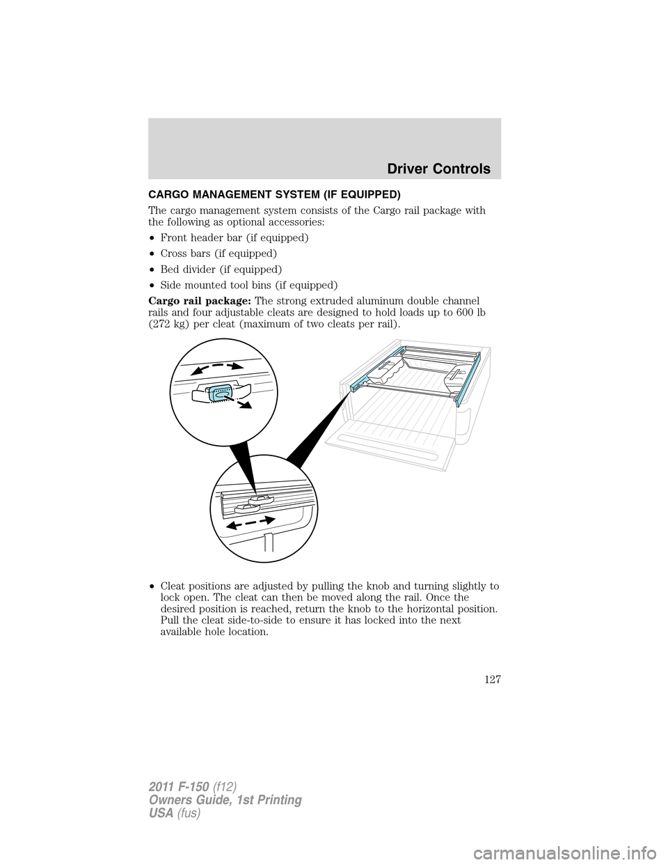
CARGO MANAGEMENT SYSTEM (IF EQUIPPED)
The cargo management system consists of the Cargo rail package with
the following as optional accessories:
•Front header bar (if equipped)
•Cross bars (if equipped)
•Bed divider (if equipped)
•Side mounted tool bins (if equipped)
Cargo rail package:The strong extruded aluminum double channel
rails and four adjustable cleats are designed to hold loads up to 600 lb
(272 kg) per cleat (maximum of two cleats per rail).
•Cleat positions are adjusted by pulling the knob and turning slightly to
lock open. The cleat can then be moved along the rail. Once the
desired position is reached, return the knob to the horizontal position.
Pull the cleat side-to-side to ensure it has locked into the next
available hole location.
Driver Controls
127
2011 F-150(f12)
Owners Guide, 1st Printing
USA(fus)
Page 128 of 461
•To remove cleat from rail, pull the knob and turn slightly to lock open
and slide it off the end of the rail.
When installing cleat, reverse instructions above.
Note:When replacing a cleat into the rail, make sure the oval embossed
on the knob is not upside down. This will ensure that the cleat is
properly oriented to accept accessory attachments.
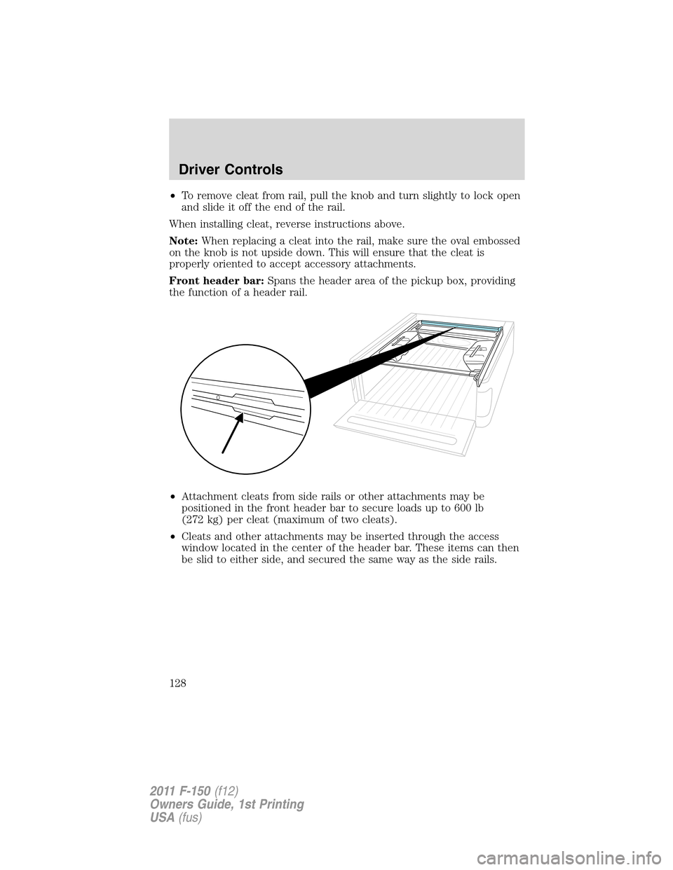
Front header bar:Spans the header area of the pickup box, providing
the function of a header rail.
•Attachment cleats from side rails or other attachments may be
positioned in the front header bar to secure loads up to 600 lb
(272 kg) per cleat (maximum of two cleats).
•Cleats and other attachments may be inserted through the access
window located in the center of the header bar. These items can then
be slid to either side, and secured the same way as the side rails.
Driver Controls
128
2011 F-150(f12)
Owners Guide, 1st Printing
USA(fus)
Page 129 of 461
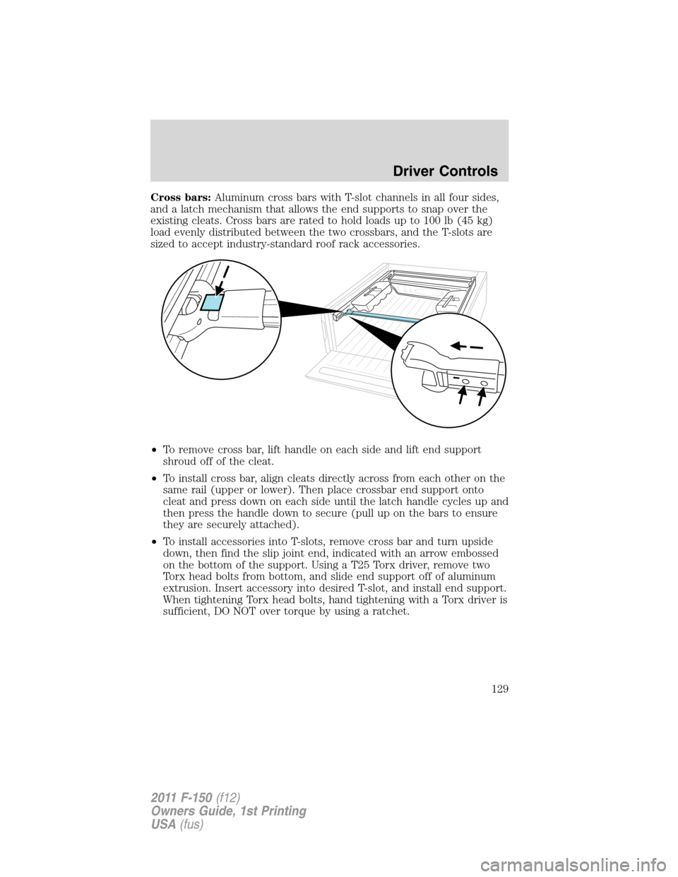
Cross bars:Aluminum cross bars with T-slot channels in all four sides,
and a latch mechanism that allows the end supports to snap over the
existing cleats. Cross bars are rated to hold loads up to 100 lb (45 kg)
load evenly distributed between the two crossbars, and the T-slots are
sized to accept industry-standard roof rack accessories.
•To remove cross bar, lift handle on each side and lift end support
shroud off of the cleat.
•To install cross bar, align cleats directly across from each other on the
same rail (upper or lower). Then place crossbar end support onto
cleat and press down on each side until the latch handle cycles up and
then press the handle down to secure (pull up on the bars to ensure
they are securely attached).
•To install accessories into T-slots, remove cross bar and turn upside
down, then find the slip joint end, indicated with an arrow embossed
on the bottom of the support. Using a T25 Torx driver, remove two
Torx head bolts from bottom, and slide end support off of aluminum
extrusion. Insert accessory into desired T-slot, and install end support.
When tightening Torx head bolts, hand tightening with a Torx driver is
sufficient, DO NOT over torque by using a ratchet.
Driver Controls
129
2011 F-150(f12)
Owners Guide, 1st Printing
USA(fus)
Page 130 of 461
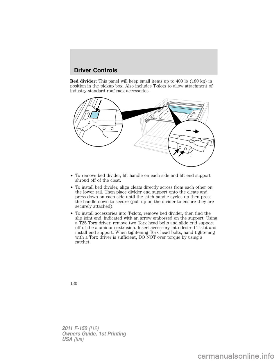
Bed divider:This panel will keep small items up to 400 lb (180 kg) in
position in the pickup box. Also includes T-slots to allow attachment of
industry-standard roof rack accessories.
•To remove bed divider, lift handle on each side and lift end support
shroud off of the cleat.
•To install bed divider, align cleats directly across from each other on
the lower rail. Then place divider end support onto the cleats and
press down on each side until the latch handle cycles up then press
the handle down to secure (pull up on the divider to ensure they are
securely attached).
•To install accessories into T-slots, remove bed divider, then find the
slip joint end, indicated with an arrow embossed on the support. Using
a T25 Torx driver, remove two Torx head bolts and slide end support
off of the aluminum extrusion. Insert accessory into desired T-slot and
install end support. When tightening Torx head bolts, hand tightening
with a Torx driver is sufficient, DO NOT over torque by using a
ratchet.
Driver Controls
130
2011 F-150(f12)
Owners Guide, 1st Printing
USA(fus)