FORD F150 2014 12.G Owners Manual
Manufacturer: FORD, Model Year: 2014, Model line: F150, Model: FORD F150 2014 12.GPages: 472, PDF Size: 4.62 MB
Page 251 of 472
6. Release the parking brake. With your
foot on the brake pedal and with the
air conditioning on, put your vehicle in
D (Drive) and allow the engine to idle
for at least one minute.
• If you do not allow the engine to
relearn its idle trim, the idle quality
of your vehicle may be adversely
affected until the idle trim is
eventually relearned.
7. Drive your vehicle to complete the relearning process
•Your vehicle may need to be driven
10 miles (16 kilometers) or more to
relearn the idle and fuel trim
strategy along with the ethanol
content for flexible fuel vehicles.
• For flexible fuel vehicles, if you are
operating on E85, you may
experience poor starts or an
inability to start the engine and
driveability problems until the fuel
trim and ethanol content have been
relearned.
If the battery has been disconnected or a
new battery has been installed, the clock
and radio settings must be reset once the
battery is reconnected.
Always dispose of automotive
batteries in a responsible manner.
Follow your local authorized standards
for disposal. Call your local authorized
recycling center to find out more about
recycling automotive batteries.
Battery Management System (If
Equipped)
The battery management system (BMS)
monitors battery conditions and takes
actions to extend battery life. If excessive
battery drain is detected, the system may
temporarily disable certain electrical
features to protect the battery. Those
electrical accessories affected include the
rear defrost, heated/cooled seats, climate control fan, heated steering wheel, audio
and navigation system. A message may be
shown in the information displays to alert
the driver that battery protection actions
are active. These messages are only for
notification that an action is taking place,
and not intended to indicate an electrical
problem or that the battery requires
replacement.
Electrical accessory installation
To ensure proper operation of the Battery
Management System, any electrical
devices that are added to your vehicle
should not have their ground connection
made directly at the negative battery post.
A connection at the negative battery post
can cause inaccurate measurements of
the battery condition and potential
incorrect system operation.
Note:
Electrical or electronic accessories
added to your vehicle by the dealer or the
owner, may adversely affect battery
performance and durability, and may affect
the performance of other electrical systems
in your vehicle.
When a battery replacement is required,
the battery should only be replaced with
a Ford-recommended replacement battery
that matches the electrical requirements
of your vehicle. After battery replacement,
or in some cases after charging the battery
with the external charger, the Battery
Management System requires eight hours
of vehicle sleep time (key off with doors
closed) to relearn the new battery state of
charge. Prior to relearning the state of
charge, the Battery Management System
may disable electrical features (to protect
the battery) earlier than normal.
248
F150 (TF6) , enUSA Maintenance
Page 252 of 472
CHECKING THE WIPER
BLADES
Run the tip of your fingers over the edge of
the blade to check for roughness.
Clean the wiper blades with washer fluid
or water applied with a soft sponge or
cloth.
CHANGING THE WIPER
BLADES
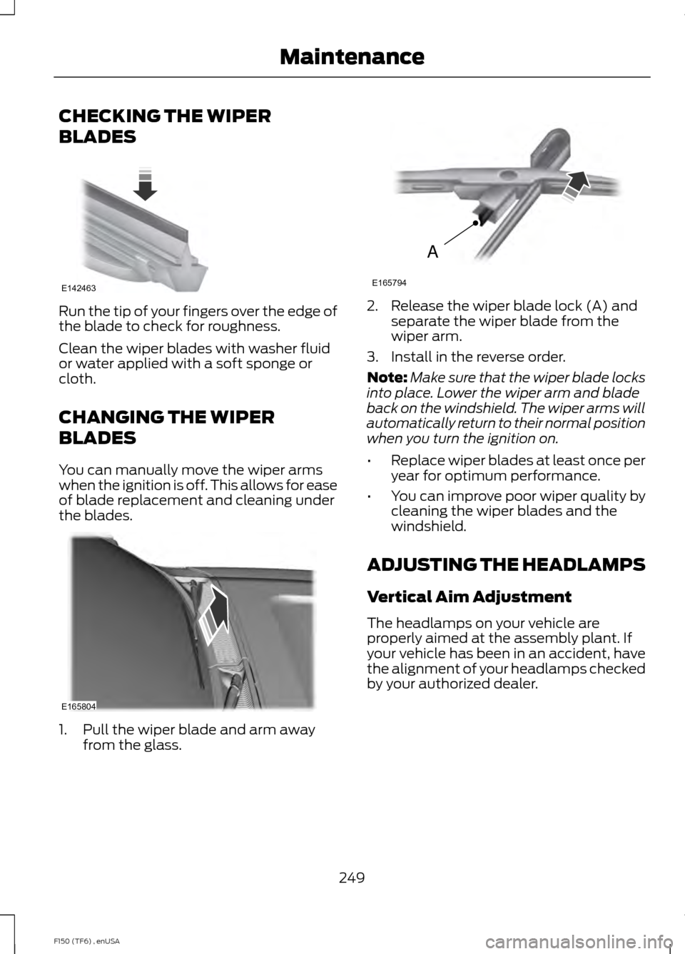
You can manually move the wiper arms
when the ignition is off. This allows for ease
of blade replacement and cleaning under
the blades.
1. Pull the wiper blade and arm away
from the glass. 2. Release the wiper blade lock (A) and
separate the wiper blade from the
wiper arm.
3. Install in the reverse order.
Note: Make sure that the wiper blade locks
into place. Lower the wiper arm and blade
back on the windshield. The wiper arms will
automatically return to their normal position
when you turn the ignition on.
• Replace wiper blades at least once per
year for optimum performance.
• You can improve poor wiper quality by
cleaning the wiper blades and the
windshield.
ADJUSTING THE HEADLAMPS
Vertical Aim Adjustment
The headlamps on your vehicle are
properly aimed at the assembly plant. If
your vehicle has been in an accident, have
the alignment of your headlamps checked
by your authorized dealer.
249
F150 (TF6) , enUSA MaintenanceE142463 E165804 A
E165794
Page 253 of 472
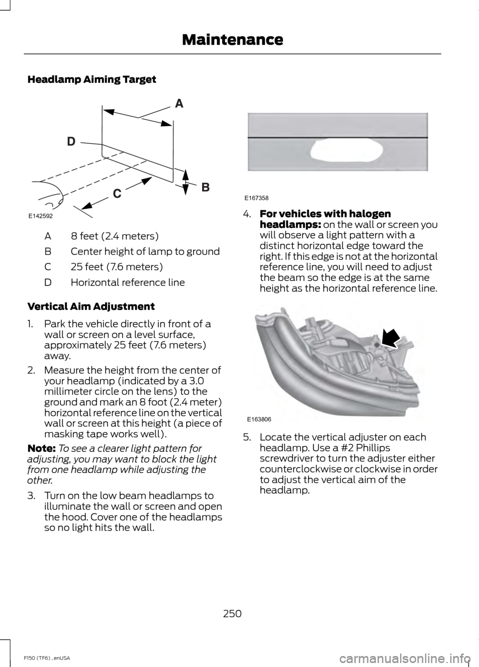
Headlamp Aiming Target
8 feet (2.4 meters)
A
Center height of lamp to ground
B
25 feet (7.6 meters)
C
Horizontal reference line
D
Vertical Aim Adjustment
1. Park the vehicle directly in front of a wall or screen on a level surface,
approximately 25 feet (7.6 meters)
away.
2. Measure the height from the center of your headlamp (indicated by a 3.0
millimeter circle on the lens) to the
ground and mark an 8 foot (2.4 meter)
horizontal reference line on the vertical
wall or screen at this height (a piece of
masking tape works well).
Note: To see a clearer light pattern for
adjusting, you may want to block the light
from one headlamp while adjusting the
other.
3. Turn on the low beam headlamps to illuminate the wall or screen and open
the hood. Cover one of the headlamps
so no light hits the wall. 4.
For vehicles with halogen
headlamps: on the wall or screen you
will observe a light pattern with a
distinct horizontal edge toward the
right. If this edge is not at the horizontal
reference line, you will need to adjust
the beam so the edge is at the same
height as the horizontal reference line. 5. Locate the vertical adjuster on each
headlamp. Use a #2 Phillips
screwdriver to turn the adjuster either
counterclockwise or clockwise in order
to adjust the vertical aim of the
headlamp.
250
F150 (TF6) , enUSA MaintenanceE142592 E167358 E163806
Page 254 of 472
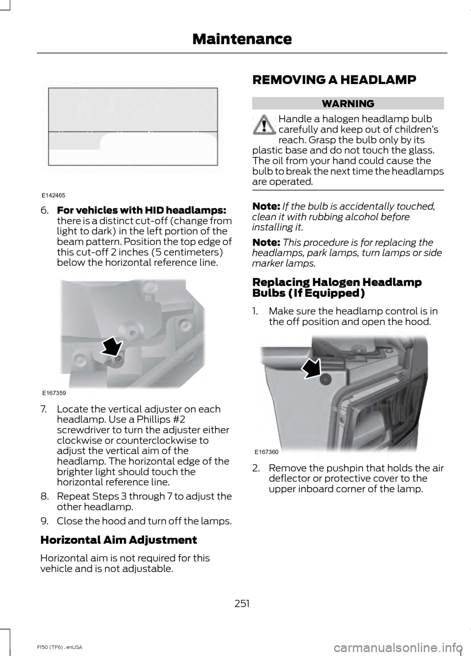
6.
For vehicles with HID headlamps:
there is a distinct cut-off (change from
light to dark) in the left portion of the
beam pattern. Position the top edge of
this cut-off 2 inches (5 centimeters)
below the horizontal reference line. 7. Locate the vertical adjuster on each
headlamp. Use a Phillips #2
screwdriver to turn the adjuster either
clockwise or counterclockwise to
adjust the vertical aim of the
headlamp. The horizontal edge of the
brighter light should touch the
horizontal reference line.
8. Repeat Steps 3 through 7 to adjust the
other headlamp.
9. Close the hood and turn off the lamps.
Horizontal Aim Adjustment
Horizontal aim is not required for this
vehicle and is not adjustable. REMOVING A HEADLAMP WARNING
Handle a halogen headlamp bulb
carefully and keep out of children
’s
reach. Grasp the bulb only by its
plastic base and do not touch the glass.
The oil from your hand could cause the
bulb to break the next time the headlamps
are operated. Note:
If the bulb is accidentally touched,
clean it with rubbing alcohol before
installing it.
Note: This procedure is for replacing the
headlamps, park lamps, turn lamps or side
marker lamps.
Replacing Halogen Headlamp
Bulbs (If Equipped)
1. Make sure the headlamp control is in the off position and open the hood. 2.
Remove the pushpin that holds the air
deflector or protective cover to the
upper inboard corner of the lamp.
251
F150 (TF6) , enUSA MaintenanceE142465 E167359 E167360
Page 255 of 472
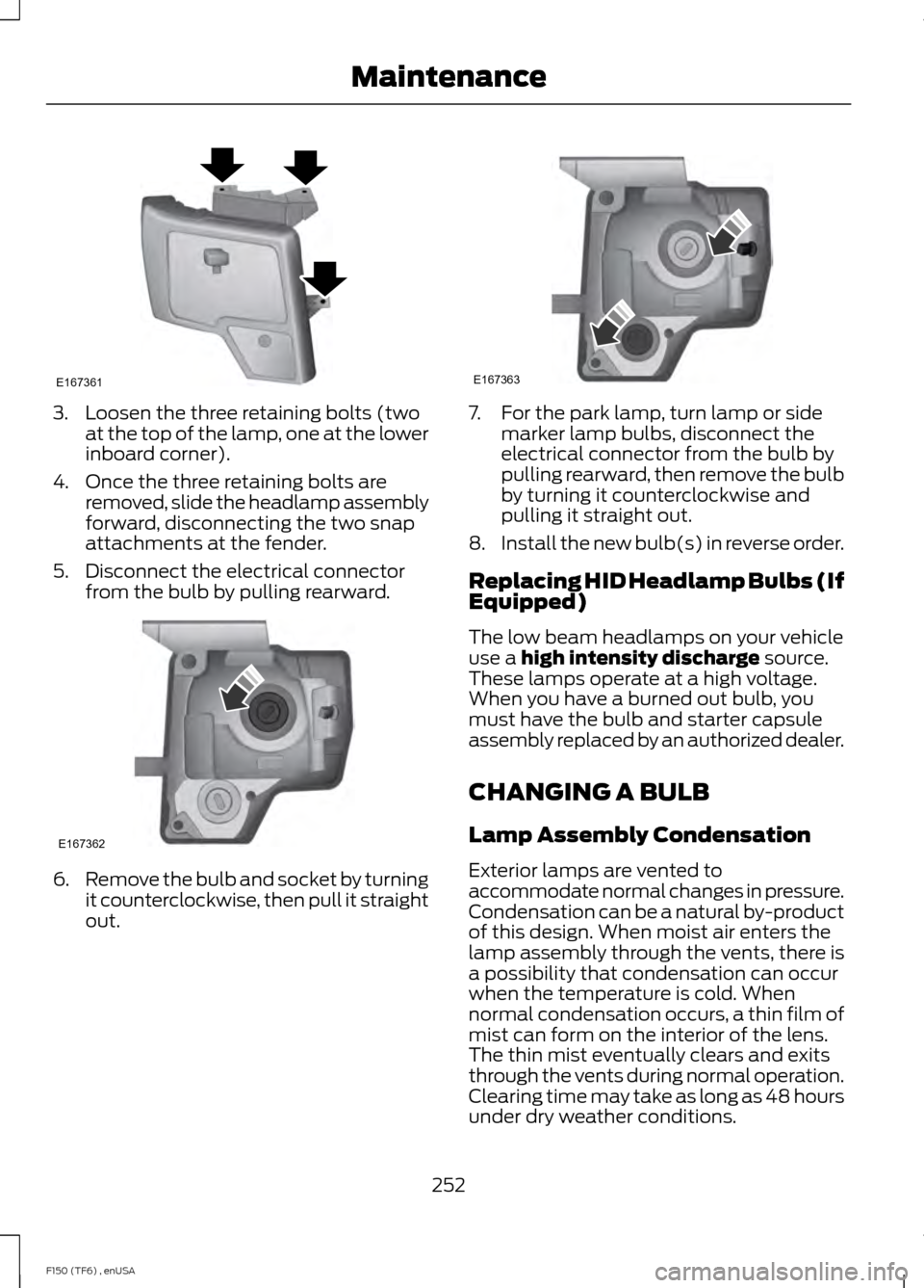
3. Loosen the three retaining bolts (two
at the top of the lamp, one at the lower
inboard corner).
4. Once the three retaining bolts are removed, slide the headlamp assembly
forward, disconnecting the two snap
attachments at the fender.
5. Disconnect the electrical connector from the bulb by pulling rearward. 6.
Remove the bulb and socket by turning
it counterclockwise, then pull it straight
out. 7. For the park lamp, turn lamp or side
marker lamp bulbs, disconnect the
electrical connector from the bulb by
pulling rearward, then remove the bulb
by turning it counterclockwise and
pulling it straight out.
8. Install the new bulb(s) in reverse order.
Replacing HID Headlamp Bulbs (If
Equipped)
The low beam headlamps on your vehicle
use a high intensity discharge source.
These lamps operate at a high voltage.
When you have a burned out bulb, you
must have the bulb and starter capsule
assembly replaced by an authorized dealer.
CHANGING A BULB
Lamp Assembly Condensation
Exterior lamps are vented to
accommodate normal changes in pressure.
Condensation can be a natural by-product
of this design. When moist air enters the
lamp assembly through the vents, there is
a possibility that condensation can occur
when the temperature is cold. When
normal condensation occurs, a thin film of
mist can form on the interior of the lens.
The thin mist eventually clears and exits
through the vents during normal operation.
Clearing time may take as long as 48 hours
under dry weather conditions.
252
F150 (TF6) , enUSA MaintenanceE167361 E167362 E167363
Page 256 of 472
Examples of acceptable condensation are:
•
Presence of thin mist (no streaks, drip
marks or droplets).
• Fine mist covers less than 50% of the
lens.
Examples of unacceptable moisture
(usually caused by a lamp water leak) are:
• Water puddle inside the lamp.
• Large water droplets, drip marks or
streaks present on the interior of the
lens.
Take your vehicle to a dealer for service if
any of the above conditions of
unacceptable moisture are present.
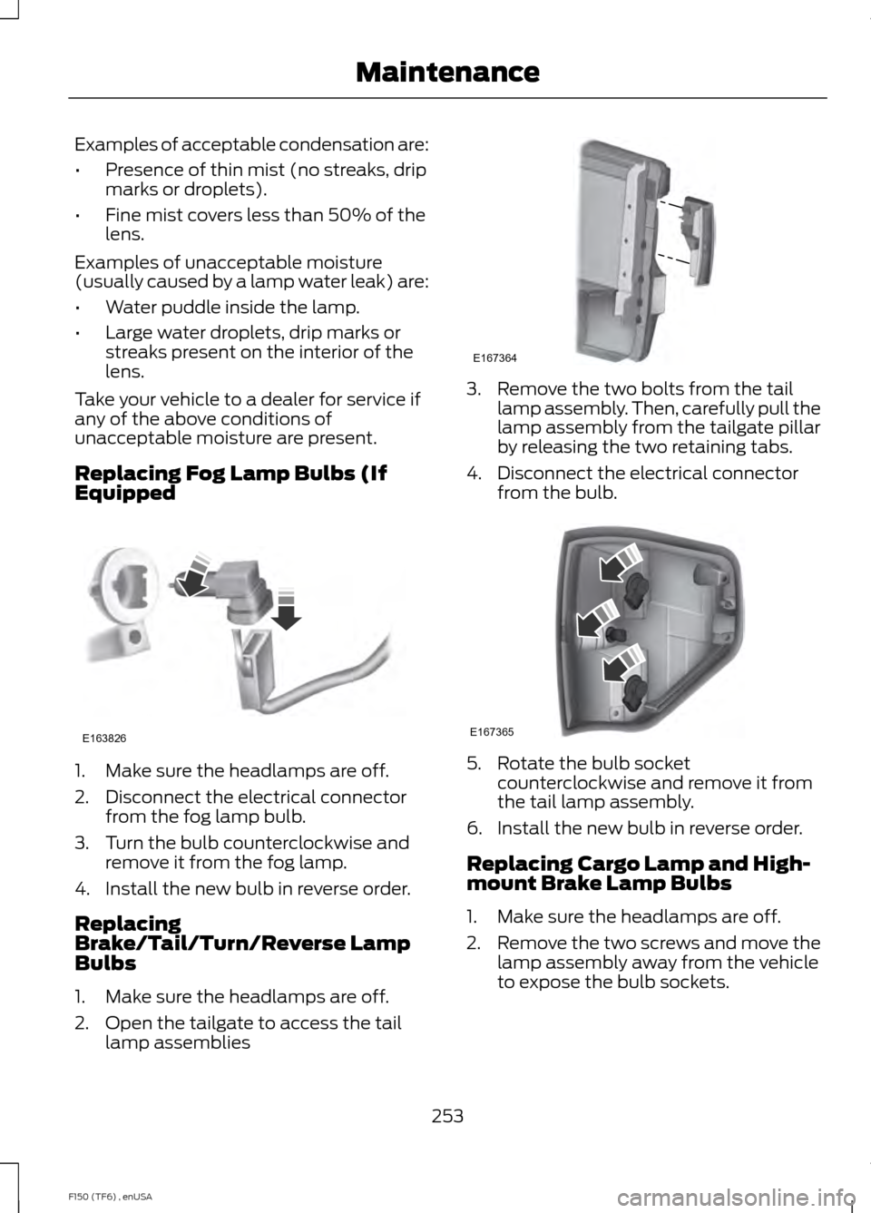
Replacing Fog Lamp Bulbs (If
Equipped 1. Make sure the headlamps are off.
2. Disconnect the electrical connector
from the fog lamp bulb.
3. Turn the bulb counterclockwise and remove it from the fog lamp.
4. Install the new bulb in reverse order.
Replacing
Brake/Tail/Turn/Reverse Lamp
Bulbs
1. Make sure the headlamps are off.
2. Open the tailgate to access the tail lamp assemblies 3. Remove the two bolts from the tail
lamp assembly. Then, carefully pull the
lamp assembly from the tailgate pillar
by releasing the two retaining tabs.
4. Disconnect the electrical connector from the bulb. 5. Rotate the bulb socket
counterclockwise and remove it from
the tail lamp assembly.
6. Install the new bulb in reverse order.
Replacing Cargo Lamp and High-
mount Brake Lamp Bulbs
1. Make sure the headlamps are off.
2. Remove the two screws and move the
lamp assembly away from the vehicle
to expose the bulb sockets.
253
F150 (TF6) , enUSA MaintenanceE163826 E167364 E167365
Page 257 of 472
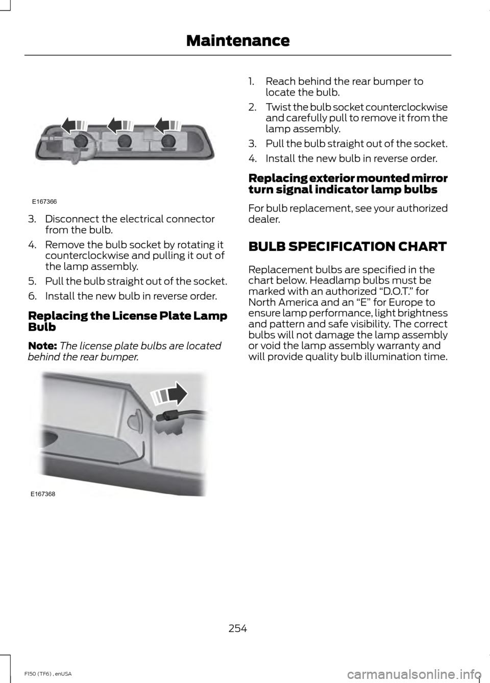
3. Disconnect the electrical connector
from the bulb.
4. Remove the bulb socket by rotating it counterclockwise and pulling it out of
the lamp assembly.
5. Pull the bulb straight out of the socket.
6. Install the new bulb in reverse order.
Replacing the License Plate Lamp
Bulb
Note: The license plate bulbs are located
behind the rear bumper. 1. Reach behind the rear bumper to
locate the bulb.
2. Twist the bulb socket counterclockwise
and carefully pull to remove it from the
lamp assembly.
3. Pull the bulb straight out of the socket.
4. Install the new bulb in reverse order.
Replacing exterior mounted mirror
turn signal indicator lamp bulbs
For bulb replacement, see your authorized
dealer.
BULB SPECIFICATION CHART
Replacement bulbs are specified in the
chart below. Headlamp bulbs must be
marked with an authorized “D.O.T.” for
North America and an “E” for Europe to
ensure lamp performance, light brightness
and pattern and safe visibility. The correct
bulbs will not damage the lamp assembly
or void the lamp assembly warranty and
will provide quality bulb illumination time.
254
F150 (TF6) , enUSA MaintenanceE167366 E167368
Page 258 of 472
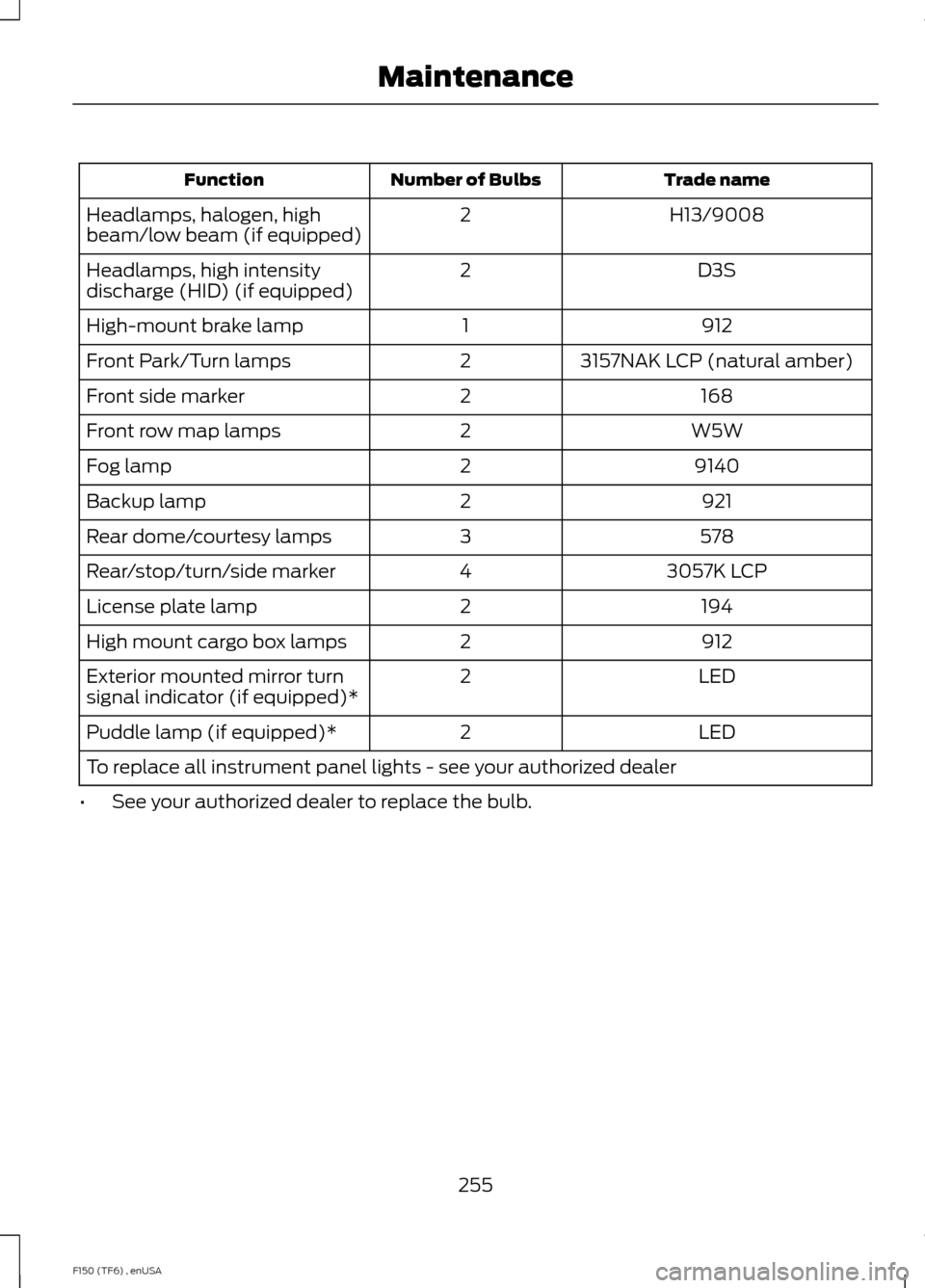
Trade name
Number of Bulbs
Function
H13/9008
2
Headlamps, halogen, high
beam/low beam (if equipped)
D3S
2
Headlamps, high intensity
discharge (HID) (if equipped)
912
1
High-mount brake lamp
3157NAK LCP (natural amber)
2
Front Park/Turn lamps
168
2
Front side marker
W5W
2
Front row map lamps
9140
2
Fog lamp
921
2
Backup lamp
578
3
Rear dome/courtesy lamps
3057K LCP
4
Rear/stop/turn/side marker
194
2
License plate lamp
912
2
High mount cargo box lamps
LED
2
Exterior mounted mirror turn
signal indicator (if equipped)*
LED
2
Puddle lamp (if equipped)*
To replace all instrument panel lights - see your authorized dealer
• See your authorized dealer to replace the bulb.
255
F150 (TF6) , enUSA Maintenance
Page 259 of 472
CHANGING THE ENGINE AIR
FILTER - 3.5L ECOBOOST™
WARNING
To reduce the risk of vehicle damage
and personal burn injuries, do not
start your engine with the air cleaner
removed and do not remove it while the
engine is running. Note:
Failure to use the correct air filter
element may result in severe engine
damage. The customer warranty may be
void for any damage to the engine if the
correct air filter element is not used.
Note: For EcoBoost equipped vehicles:
When servicing the air cleaner, it is
important that no foreign material enter the
air induction system. The engine and
turbocharger are susceptible to damage
from even small particles.
When changing the air filter element, use
only the air filter element listed. See
Capacities and Specifications (page
296).
Change the air filter element at the proper
interval.
See Scheduled Maintenance
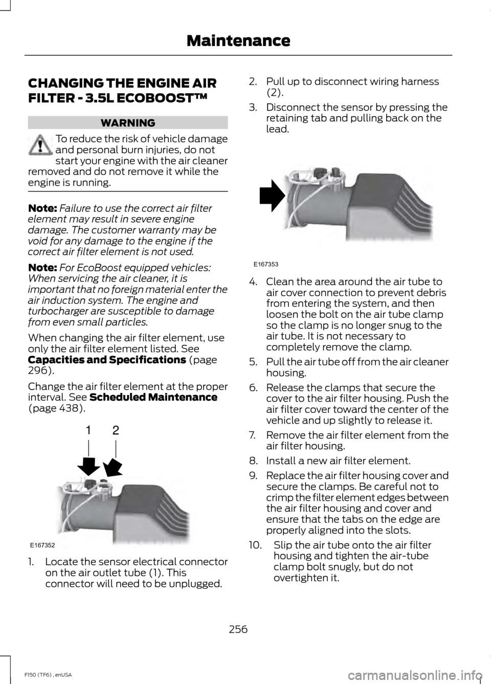
(page 438). 1.
Locate the sensor electrical connector
on the air outlet tube (1). This
connector will need to be unplugged. 2. Pull up to disconnect wiring harness
(2).
3. Disconnect the sensor by pressing the retaining tab and pulling back on the
lead. 4. Clean the area around the air tube to
air cover connection to prevent debris
from entering the system, and then
loosen the bolt on the air tube clamp
so the clamp is no longer snug to the
air tube. It is not necessary to
completely remove the clamp.
5. Pull the air tube off from the air cleaner
housing.
6. Release the clamps that secure the cover to the air filter housing. Push the
air filter cover toward the center of the
vehicle and up slightly to release it.
7. Remove the air filter element from the
air filter housing.
8. Install a new air filter element.
9. Replace the air filter housing cover and
secure the clamps. Be careful not to
crimp the filter element edges between
the air filter housing and cover and
ensure that the tabs on the edge are
properly aligned into the slots.
10. Slip the air tube onto the air filter housing and tighten the air-tube
clamp bolt snugly, but do not
overtighten it.
256
F150 (TF6) , enUSA MaintenanceE167352
12 E167353
Page 260 of 472
11. Reconnect the sensor electrical
connector to the outlet tube.
12. Push the wiring harness back in place.
CHANGING THE ENGINE AIR
FILTER - 3.7L/5.0L/6.2L WARNING
To reduce the risk of vehicle damage
and personal burn injuries, do not
start your engine with the air cleaner
removed and do not remove it while the
engine is running. Note:
Failure to use the correct air filter
element may result in severe engine
damage. The customer warranty may be
void for any damage to the engine if the
correct air filter element is not used.
Note: For EcoBoost equipped vehicles:
When servicing the air cleaner, it is
important that no foreign material enter the
air induction system. The engine and
turbocharger are susceptible to damage
from even small particles.
When changing the air filter element, use
only the air filter element listed. See
Capacities and Specifications (page
296).
Change the air filter element at the proper
interval.
See Scheduled Maintenance
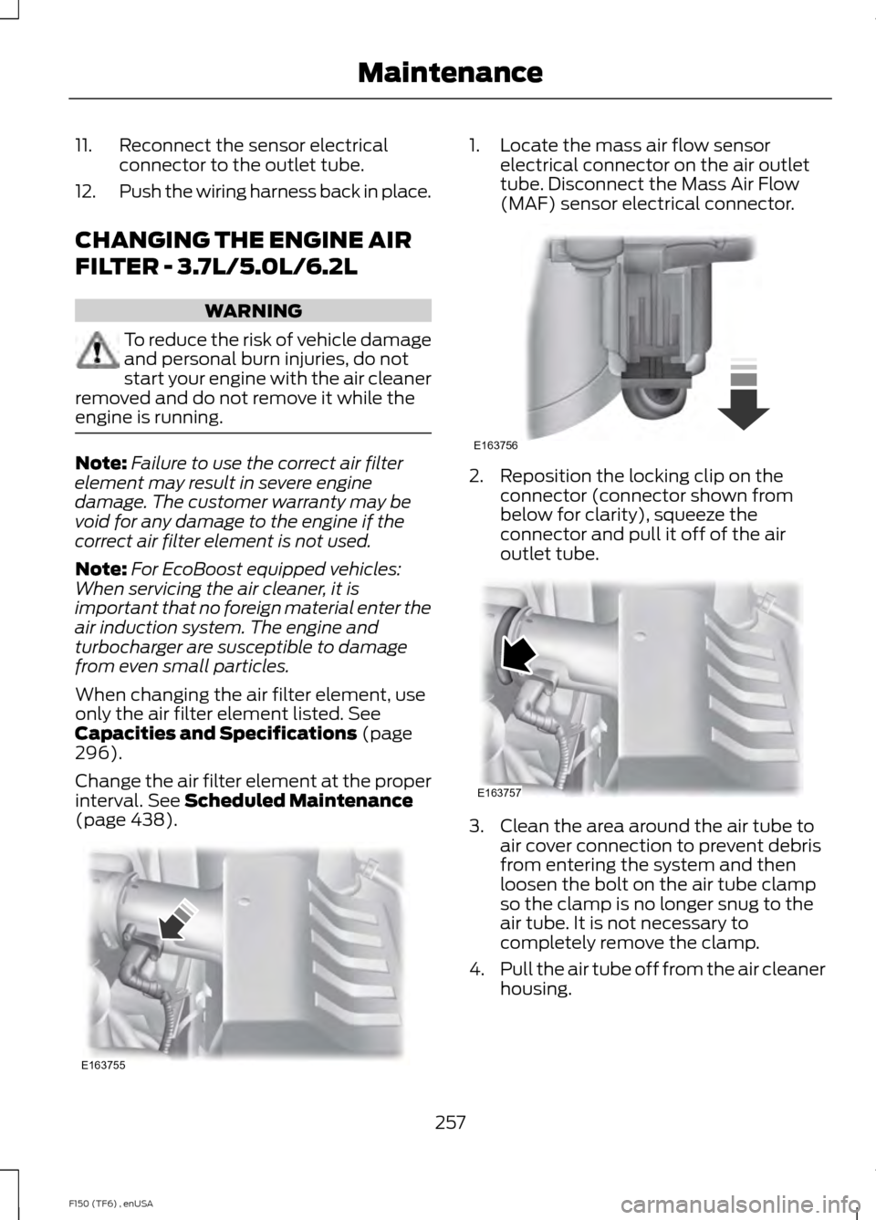
(page 438). 1. Locate the mass air flow sensor
electrical connector on the air outlet
tube. Disconnect the Mass Air Flow
(MAF) sensor electrical connector. 2. Reposition the locking clip on the
connector (connector shown from
below for clarity), squeeze the
connector and pull it off of the air
outlet tube. 3. Clean the area around the air tube to
air cover connection to prevent debris
from entering the system and then
loosen the bolt on the air tube clamp
so the clamp is no longer snug to the
air tube. It is not necessary to
completely remove the clamp.
4. Pull the air tube off from the air cleaner
housing.
257
F150 (TF6) , enUSA MaintenanceE163755 E163756 E163757