jack FORD F150 2017 13.G Owners Manual
[x] Cancel search | Manufacturer: FORD, Model Year: 2017, Model line: F150, Model: FORD F150 2017 13.GPages: 599, PDF Size: 7.34 MB
Page 11 of 599
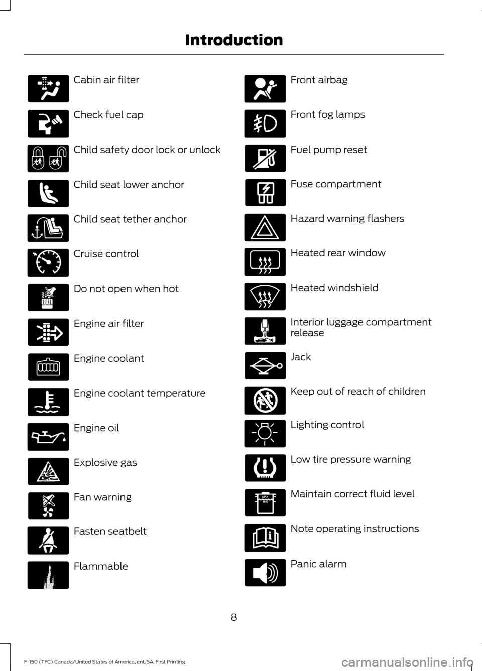
Cabin air filter
Check fuel cap
Child safety door lock or unlock
Child seat lower anchor
Child seat tether anchor
Cruise control
Do not open when hot
Engine air filter
Engine coolant
Engine coolant temperature
Engine oil
Explosive gas
Fan warning
Fasten seatbelt
Flammable Front airbag
Front fog lamps
Fuel pump reset
Fuse compartment
Hazard warning flashers
Heated rear window
Heated windshield
Interior luggage compartment
release
Jack
Keep out of reach of children
Lighting control
Low tire pressure warning
Maintain correct fluid level
Note operating instructions
Panic alarm
8
F-150 (TFC) Canada/United States of America, enUSA, First Printing Introduction E71340 E231160 E161353
Page 81 of 599
USING POWER RUNNING
BOARDS
WARNINGS
In extreme climates, excessive ice
buildup may occur, causing the
running boards not to deploy. Make
sure that the running boards have
deployed, and have finished moving before
attempting to step on them. The running
boards will resume normal function once
the blockage is cleared. Turn off the running boards before
jacking or placing any object under
your vehicle. Never place your hand
between the extended running board and
your vehicle. A moving running board may
cause injury. Note:
Do not use the running boards, front
and rear hinge assemblies, running board
motors, or the running board underbody
mounts to lift your vehicle when jacking.
Always use proper jacking points.
Note: The running boards may operate
more slowly in cool temperatures.
Note: The running board mechanism may
trap debris such as mud, dirt, snow, ice and
salt. This may cause unwanted noise. If this
happens, manually set the running boards
to the deployed position. Then, wash the
system, in particular the front and rear hinge
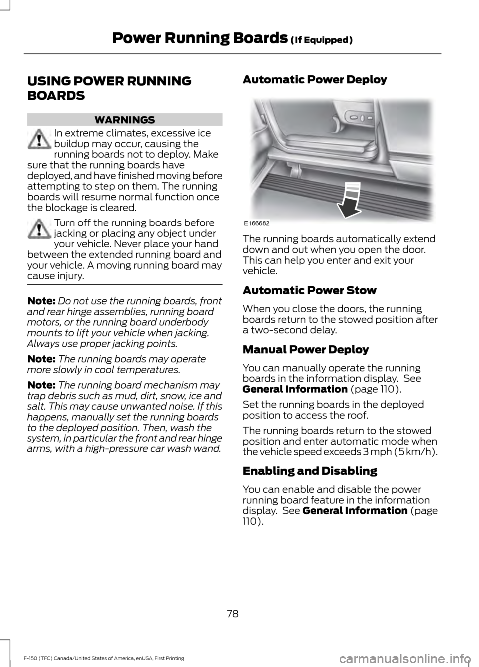
arms, with a high-pressure car wash wand. Automatic Power Deploy The running boards automatically extend
down and out when you open the door.
This can help you enter and exit your
vehicle.
Automatic Power Stow
When you close the doors, the running
boards return to the stowed position after
a two-second delay.
Manual Power Deploy
You can manually operate the running
boards in the information display. See
General Information (page 110).
Set the running boards in the deployed
position to access the roof.
The running boards return to the stowed
position and enter automatic mode when
the vehicle speed exceeds 3 mph (5 km/h).
Enabling and Disabling
You can enable and disable the power
running board feature in the information
display. See
General Information (page
110).
78
F-150 (TFC) Canada/United States of America, enUSA, First Printing Power Running Boards
(If Equipped)E166682
Page 169 of 599
CENTER CONSOLE (If Equipped)
Stow items in the cup holder carefully as
items may become loose during hard
braking, acceleration or crashes, including
hot drinks which may spill.
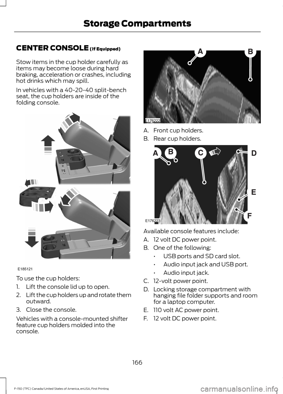
In vehicles with a 40-20-40 split-bench
seat, the cup holders are inside of the
folding console. To use the cup holders:
1. Lift the console lid up to open.
2.
Lift the cup holders up and rotate them
outward.
3. Close the console.
Vehicles with a console-mounted shifter
feature cup holders molded into the
console. A. Front cup holders.
B. Rear cup holders.
Available console features include:
A. 12 volt DC power point.
B. One of the following:
•USB ports and SD card slot.
• Audio input jack and USB port.
• Audio input jack.
C. 12-volt power point.
D. Locking storage compartment with hanging file folder supports and room
for a laptop computer.
E. 110 volt AC power point.
F. 12 volt DC power point.
166
F-150 (TFC) Canada/United States of America, enUSA, First Printing Storage CompartmentsE185121 E176222 E176223
Page 255 of 599
- 1200 = - 240 pounds. No, you do
not have enough cargo capacity
to carry that much weight. In
metric units, the calculation would
be: 635 kilograms - (2 x 99
kilograms) - (12 x 45 kilograms) =
635 - 198 - 540 = -103 kilograms.
You will need to reduce the load
weight by at least 240 pounds
(104 kilograms). If you remove
three 100-pound (45-kilogram)
cement bags, then the load
calculation would be:1400 - (2 x
220) - (9 x 100) = 1400 - 440 -
900 = 60 pounds. Now you have
the load capacity to transport the
cement and your friend home. In
metric units, the calculation would
be: 635 kilograms - (2 x 99
kilograms) - (9 x 45 kilograms) =
635 - 198 - 405 = 32 kilograms.
The above calculations also
assume that the loads are
positioned in your vehicle in a
manner that does not overload
the front or the rear gross axle
weight rating specified for your
vehicle on the Safety Compliance
Certification label.
Special Loading Instructions
for Owners of Pick-up Trucks
and Utility-type Vehicles
WARNING
Loaded vehicles may handle
differently than unloaded
vehicles. Take extra precautions,
such as slower speeds and
increased stopping distance, when
driving a heavily loaded vehicle. BED ACCESS (If Equipped)
Box Side Step
Use the step for easier access to the
vehicle bed.
Note: Close the step before driving.
Note: Do not exceed
500 lb (227 kg) on
the step. This includes you plus cargo.
Note: Do not use the step to lift the vehicle.
Only use proper jacking points.
Note: The step may operate more slowly
in cool temperatures.
Note: The step mechanism may trap debris
such as mud, dirt, snow, ice and salt. This
may prevent the step from deploying
automatically when you press the button.
If this happens, make sure that you press
the button down and carefully pull out the
step manually. Wash off the debris with a
high-pressure sprayer and stow the step.
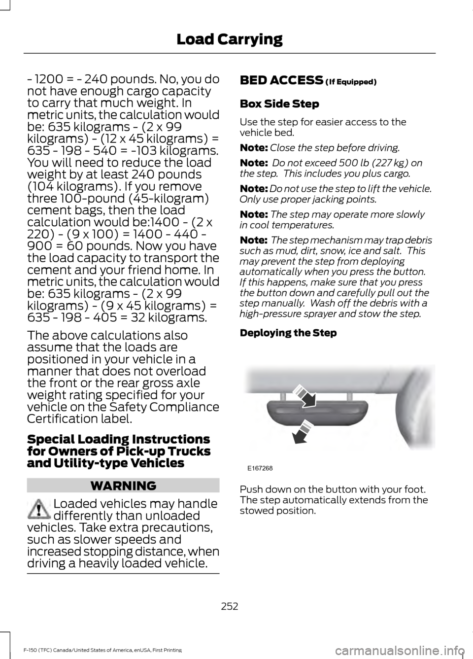
Deploying the Step Push down on the button with your foot.
The step automatically extends from the
stowed position.
252
F-150 (TFC) Canada/United States of America, enUSA, First Printing Load CarryingE167268
Page 262 of 599
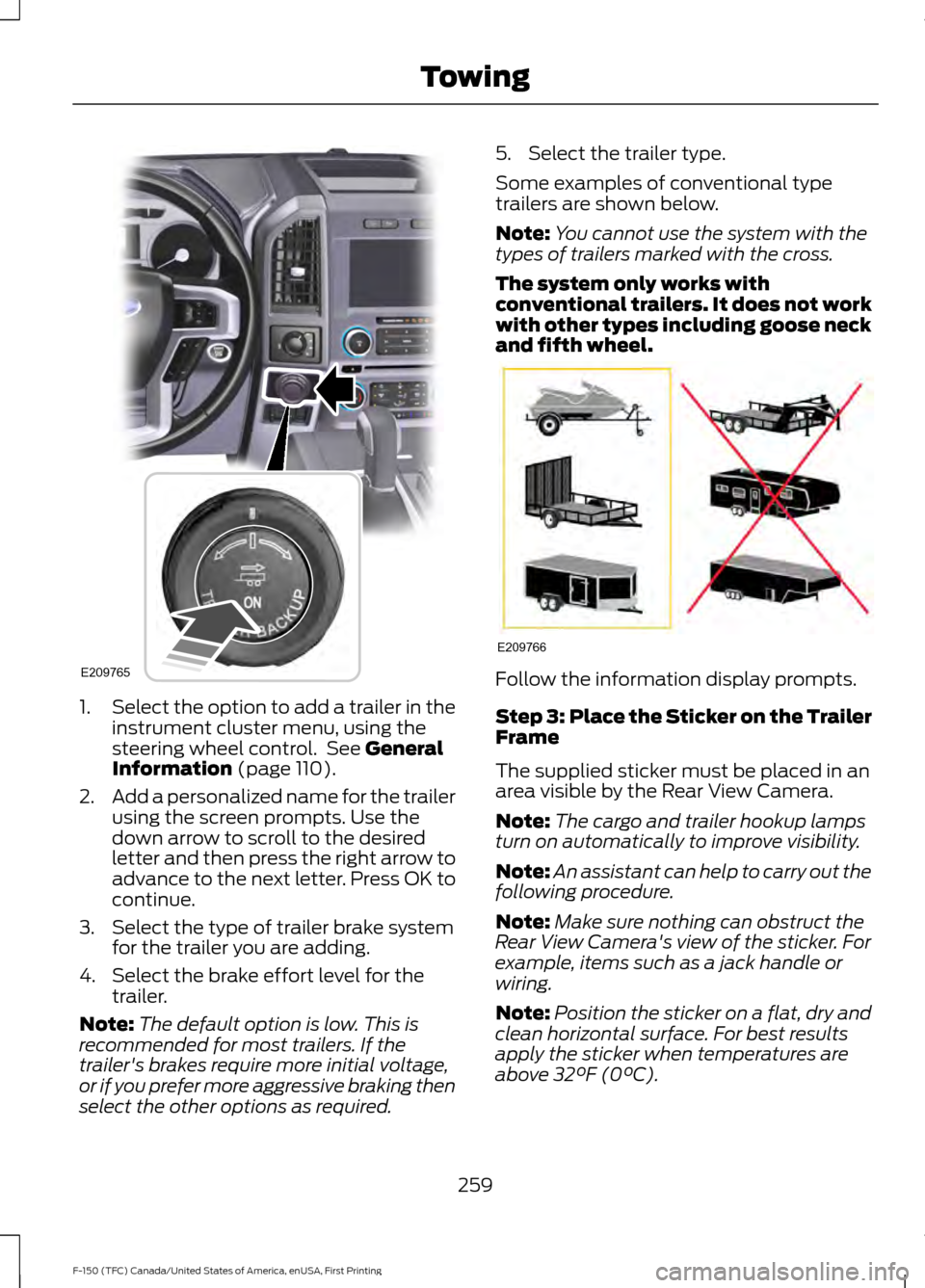
1.
Select the option to add a trailer in the
instrument cluster menu, using the
steering wheel control. See General
Information (page 110).
2. Add a personalized name for the trailer
using the screen prompts. Use the
down arrow to scroll to the desired
letter and then press the right arrow to
advance to the next letter. Press OK to
continue.
3. Select the type of trailer brake system for the trailer you are adding.
4. Select the brake effort level for the trailer.
Note: The default option is low. This is
recommended for most trailers. If the
trailer's brakes require more initial voltage,
or if you prefer more aggressive braking then
select the other options as required. 5. Select the trailer type.
Some examples of conventional type
trailers are shown below.
Note:
You cannot use the system with the
types of trailers marked with the cross.
The system only works with
conventional trailers. It does not work
with other types including goose neck
and fifth wheel. Follow the information display prompts.
Step 3: Place the Sticker on the Trailer
Frame
The supplied sticker must be placed in an
area visible by the Rear View Camera.
Note:
The cargo and trailer hookup lamps
turn on automatically to improve visibility.
Note: An assistant can help to carry out the
following procedure.
Note: Make sure nothing can obstruct the
Rear View Camera's view of the sticker. For
example, items such as a jack handle or
wiring.
Note: Position the sticker on a flat, dry and
clean horizontal surface. For best results
apply the sticker when temperatures are
above
32°F (0°C).
259
F-150 (TFC) Canada/United States of America, enUSA, First Printing TowingE209765 E209766
Page 376 of 599
•
Use commercial car washing
equipment.
• Try to repair the dissimilar spare tire.
Use of one of the dissimilar spare tires
listed above at any one wheel location can
lead to impairment of the following:
• Handling, stability and braking
performance.
• Comfort and noise.
• Ground clearance and parking at curbs.
• Winter weather driving capability.
• Wet weather driving capability.
• All-wheel driving capability.
3. Full-size dissimilar spare without
label on wheel
When driving with the full-size dissimilar
spare wheel and tire assembly, do not:
• Exceed 70 mph (120 km/h).
• Use more than one dissimilar spare
wheel and tire assembly at a time.
• Use commercial car washing
equipment.
• Use snow chains on the end of the
vehicle with the dissimilar spare wheel
and tire assembly.
The usage of a full-size dissimilar spare
wheel and tire assembly can lead to
impairment of the following:
• Handling, stability and braking
performance.
• Comfort and noise.
• Ground clearance and parking at curbs.
• Winter weather driving capability.
• Wet weather driving capability.
• All-wheel driving capability. When driving with the full-size dissimilar
spare wheel and tire assembly additional
caution should be given to:
•
Towing a trailer.
• Driving vehicles equipped with a
camper body.
• Driving vehicles with a load on the
cargo rack.
Drive cautiously when using a full-size
dissimilar spare wheel and tire assembly
and seek service as soon as possible.
Tire Change Procedure WARNINGS
When one of the front wheels is off
the ground, the transmission alone
will not prevent the vehicle from
moving or slipping off the jack, even if the
transmission is in park (P). To help prevent your vehicle from
moving when changing a wheel, shift
the transmission into park (P), set
the parking brake and use an appropriate
block or wheel chock to secure the wheel
diagonally opposite to the wheel being
changed. For example, when changing the
front left wheel, place an appropriate block
or wheel chock on the right rear wheel. Do not work on your vehicle when
the jack is the only support. If the
vehicle slips off the jack, you or
someone else could be seriously injured. Do not attempt to change a tire on
the side of the vehicle close to
moving traffic. Pull far enough off the
road to avoid the danger of being hit when
operating the jack or changing the wheel.
373
F-150 (TFC) Canada/United States of America, enUSA, First Printing Wheels and Tires
Page 377 of 599
WARNINGS
Always use the jack provided as
original equipment with your vehicle.
If using a jack other than the one
provided, make sure the jack capacity is
adequate for the vehicle weight, including
any vehicle cargo or modifications. If you
are unsure if the jack capacity is adequate,
contact the authorized dealer. Switch off the running boards before
jacking or placing any object under
your vehicle. Never place your hand
between the extended running board and
your vehicle. A moving running board may
cause injury. Note:
Only use the spare tire carrier to stow
the tire and wheel combination provided
with your vehicle. Other tire and wheel
combinations can cause the tire carrier to
fail.
Note: Do not use impact tools or power
tools operating at over 200 RPM on the
spare tire carrier, this may cause a winch
malfunction and prevent a secure fit.
Override the winch at least three times
(there will be an audible click each time) to
make sure the wheel and tire have been
installed securely.
Note: Passengers should not remain in the
vehicle when the vehicle is being jacked.
Park on a level surface, activate the hazard
flashers and set the parking brake. Then,
place the transmission in park (P) and turn
the engine off.
Remove the Vehicle Jack and Tool Bag
The vehicle jack and tool bag are located
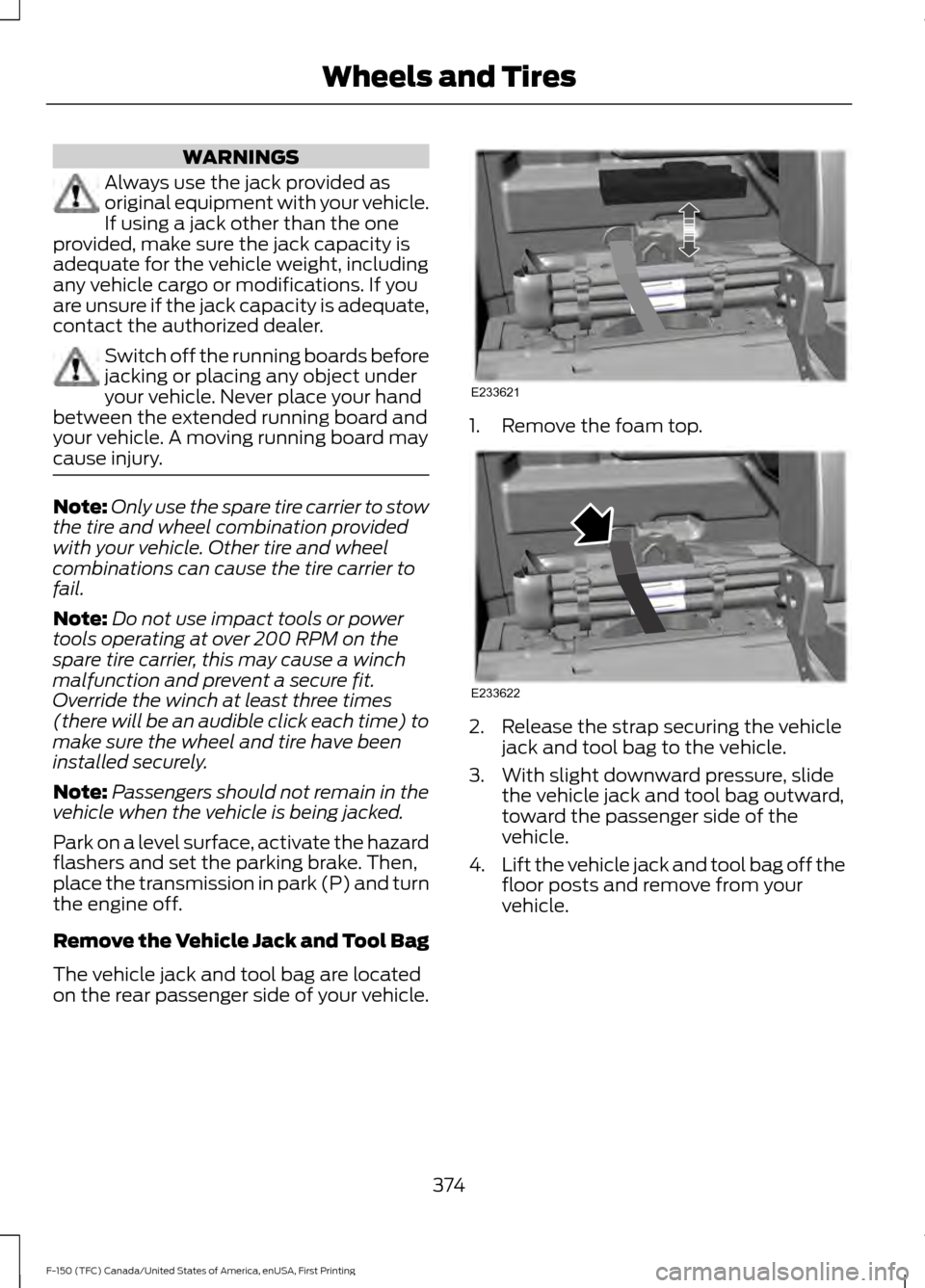
on the rear passenger side of your vehicle. 1. Remove the foam top.
2. Release the strap securing the vehicle
jack and tool bag to the vehicle.
3. With slight downward pressure, slide the vehicle jack and tool bag outward,
toward the passenger side of the
vehicle.
4. Lift the vehicle jack and tool bag off the
floor posts and remove from your
vehicle.
374
F-150 (TFC) Canada/United States of America, enUSA, First Printing Wheels and TiresE233621 E233622
Page 378 of 599

5. With the vehicle jack and tool bag
removed from your vehicle, remove the
fuel funnel. 6. Release the D-ring straps.
7.
Lift the tool bag off of the vehicle jack. 8. Remove the tools from the tool bag.
Note:
Only Raptor trim vehicles receive a
wheel chock with the tool bag.
Removing the Spare Tire
Note: Remove the hook end from the
assembled jack handle before continuing.
The spare tire is located under the vehicle,
just forward of the rear bumper.
1. Use your key to remove the lock cylinder from the access hole of the
bumper to allow access to the guide
tube. 375
F-150 (TFC) Canada/United States of America, enUSA, First Printing Wheels and TiresE233623 E233624 E233625 E233626 E188735
Page 379 of 599
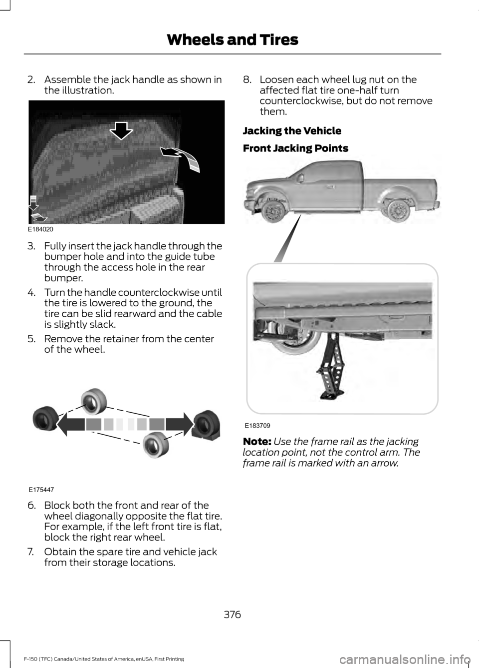
2. Assemble the jack handle as shown in
the illustration. 3.
Fully insert the jack handle through the
bumper hole and into the guide tube
through the access hole in the rear
bumper.
4. Turn the handle counterclockwise until
the tire is lowered to the ground, the
tire can be slid rearward and the cable
is slightly slack.
5. Remove the retainer from the center of the wheel. 6. Block both the front and rear of the
wheel diagonally opposite the flat tire.
For example, if the left front tire is flat,
block the right rear wheel.
7. Obtain the spare tire and vehicle jack from their storage locations. 8. Loosen each wheel lug nut on the
affected flat tire one-half turn
counterclockwise, but do not remove
them.
Jacking the Vehicle
Front Jacking Points Note:
Use the frame rail as the jacking
location point, not the control arm. The
frame rail is marked with an arrow.
376
F-150 (TFC) Canada/United States of America, enUSA, First Printing Wheels and TiresE184020 E175447 E183709
Page 380 of 599
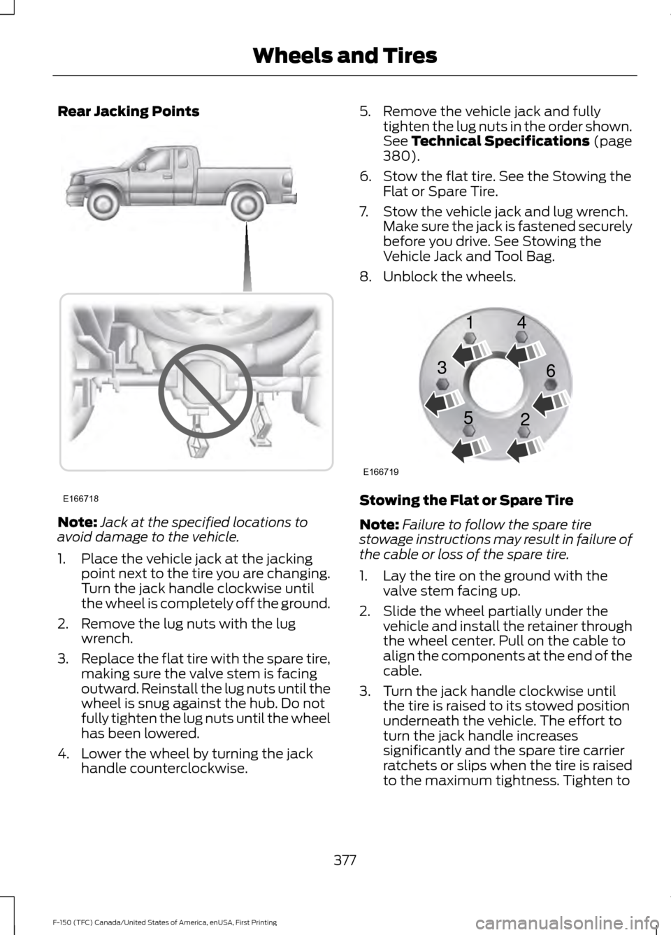
Rear Jacking Points
Note:
Jack at the specified locations to
avoid damage to the vehicle.
1. Place the vehicle jack at the jacking point next to the tire you are changing.
Turn the jack handle clockwise until
the wheel is completely off the ground.
2. Remove the lug nuts with the lug wrench.
3. Replace the flat tire with the spare tire,
making sure the valve stem is facing
outward. Reinstall the lug nuts until the
wheel is snug against the hub. Do not
fully tighten the lug nuts until the wheel
has been lowered.
4. Lower the wheel by turning the jack handle counterclockwise. 5. Remove the vehicle jack and fully
tighten the lug nuts in the order shown.
See Technical Specifications (page
380).
6. Stow the flat tire. See the Stowing the Flat or Spare Tire.
7. Stow the vehicle jack and lug wrench. Make sure the jack is fastened securely
before you drive. See Stowing the
Vehicle Jack and Tool Bag.
8. Unblock the wheels. Stowing the Flat or Spare Tire
Note:
Failure to follow the spare tire
stowage instructions may result in failure of
the cable or loss of the spare tire.
1. Lay the tire on the ground with the valve stem facing up.
2. Slide the wheel partially under the vehicle and install the retainer through
the wheel center. Pull on the cable to
align the components at the end of the
cable.
3. Turn the jack handle clockwise until the tire is raised to its stowed position
underneath the vehicle. The effort to
turn the jack handle increases
significantly and the spare tire carrier
ratchets or slips when the tire is raised
to the maximum tightness. Tighten to
377
F-150 (TFC) Canada/United States of America, enUSA, First Printing Wheels and TiresE166718 E166719
1
3
5 4
6
2