FORD F250 SUPER DUTY 2017 Owners Manual
Manufacturer: FORD, Model Year: 2017, Model line: F250 SUPER DUTY, Model: FORD F250 SUPER DUTY 2017Pages: 642, PDF Size: 12.35 MB
Page 271 of 642
TOWING A TRAILER
WARNINGS
Towing trailers beyond themaximum recommendedgross trailer weight exceeds thelimit of your vehicle and couldresult in engine damage,transmission damage, structuraldamage, loss of vehicle control,vehicle rollover and personalinjury.
Do not exceed the GVWR orthe GAWR specified on thecertification label.
Note: See RecommendedTowing Weights (page 277).
Your vehicle may have electricalitems, such as fuses or relays,related to towing. See Fuses(page 312).
Your vehicle's load capacitydesignation is by weight, not byvolume, so you cannot necessarilyuse all available space whenloading a vehicle or trailer.
Towing a trailer places an extraload on your vehicle's engine,transmission, axle, brakes, tiresand suspension. Inspect thesecomponents periodically during,and after, any towing operation.
Load Placement
To help minimize how trailermovement affects your vehiclewhen driving:
•Load the heaviest items closestto the trailer floor.
•Load the heaviest itemscentered between the left andright side trailer tires.
•Load the heaviest items abovethe trailer axles or just slightlyforward toward the trailertongue. Do not allow the finaltrailer tongue weight to goabove or below 10-15% of theloaded trailer weight.
•Select a ball mount with thecorrect rise or drop and loadcapacity. When both theloaded vehicle and trailer areconnected, the trailer frameshould be level, or slightlyangled down toward yourvehicle, when viewed from theside.
When driving with a trailer orpayload, a slight takeoff vibrationor shudder may be present due tothe increased payload weight.Additional information regardingproper trailer loading and settingyour vehicle up for towing islocated in another chapter of thismanual. See Load Limit (page261).
You can also find information inthe RV & Trailer Towing Guideavailable at your authorizeddealer, or online.
268
Super Duty (TFE) Canada/United States of America, enUSA, Edition date: 201710, Second Printing
Towing
Page 272 of 642
RV & Trailer Towing Guide Online
http://www.fleet.ford.com/towing-guides/Website
TRAILER REVERSING AIDS
Trailer Reverse Guidance
WARNING
Driving while distracted can result inloss of vehicle control, crash andinjury. We strongly recommend thatyou use extreme caution when using anydevice that may take your focus off theroad. Your primary responsibility is the safeoperation of your vehicle. We recommendagainst the use of any hand-held devicewhile driving and encourage the use ofvoice-operated systems when possible.Make sure you are aware of all applicablelocal laws that may affect the use ofelectronic devices while driving.
Note:The system is not a substitute forsafe driving practices.
Note:You must always be aware of thevehicle and trailer combination and thesurrounding environment.
Note:The system does not detect orprevent the vehicle or trailer from makingcontact with obstacles in the surroundingenvironment.
Note:Keep in mind that the front end ofthe vehicle swings out when changing thedirection of the trailer.
Note:The system relies on usermeasurements to determine stickerplacement and system limits. It is critical totake the key measurements correctly.Incorrect measurements can result in theimproper function of the system up to andincluding contact between the vehicle andtrailer.
Note:The system limits vehicle speed whenbacking up. The system is not a replacementfor proper use of the throttle and brakepedals.
Principle of Operation
Trailer Reverse Guidance (TRG) is a driverassistance feature that helps take theguesswork out of getting your trailerpositioned where you want it, quickly andeasily, while you're driving in reverse.
Each trailer you use with your vehicle hasto be setup once.
Sticker placement is extremely importantand there are specific placement rules.
Setting Up Trailer ReverseGuidance
Note:Once you have entered a trailer'sinformation into the system, it is stored foreasy recall. A maximum of 10 trailers can beadded to the system.
Step 1: Position your Vehicle and Trailer
Hitch your trailer to the truck and connectthe electrical wiring harness. Check tomake sure that the wiring is working SeeEssential Towing Checks (page 281).
Park your vehicle and hitched trailer on alevel surface.
269
Super Duty (TFE) Canada/United States of America, enUSA, Edition date: 201710, Second Printing
Towing
Page 273 of 642
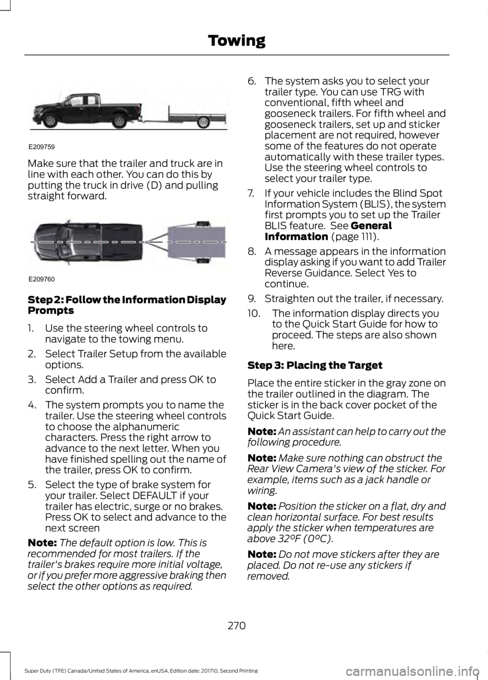
Make sure that the trailer and truck are inline with each other. You can do this byputting the truck in drive (D) and pullingstraight forward.
Step 2: Follow the Information DisplayPrompts
1. Use the steering wheel controls tonavigate to the towing menu.
2.Select Trailer Setup from the availableoptions.
3. Select Add a Trailer and press OK toconfirm.
4. The system prompts you to name thetrailer. Use the steering wheel controlsto choose the alphanumericcharacters. Press the right arrow toadvance to the next letter. When youhave finished spelling out the name ofthe trailer, press OK to confirm.
5. Select the type of brake system foryour trailer. Select DEFAULT if yourtrailer has electric, surge or no brakes.Press OK to select and advance to thenext screen
Note:The default option is low. This isrecommended for most trailers. If thetrailer's brakes require more initial voltage,or if you prefer more aggressive braking thenselect the other options as required.
6. The system asks you to select yourtrailer type. You can use TRG withconventional, fifth wheel andgooseneck trailers. For fifth wheel andgooseneck trailers, set up and stickerplacement are not required, howeversome of the features do not operateautomatically with these trailer types.Use the steering wheel controls toselect your trailer type.
7. If your vehicle includes the Blind SpotInformation System (BLIS), the systemfirst prompts you to set up the TrailerBLIS feature. See GeneralInformation (page 111).
8. A message appears in the informationdisplay asking if you want to add TrailerReverse Guidance. Select Yes tocontinue.
9. Straighten out the trailer, if necessary.
10. The information display directs youto the Quick Start Guide for how toproceed. The steps are also shownhere.
Step 3: Placing the Target
Place the entire sticker in the gray zone onthe trailer outlined in the diagram. Thesticker is in the back cover pocket of theQuick Start Guide.
Note:An assistant can help to carry out thefollowing procedure.
Note:Make sure nothing can obstruct theRear View Camera's view of the sticker. Forexample, items such as a jack handle orwiring.
Note:Position the sticker on a flat, dry andclean horizontal surface. For best resultsapply the sticker when temperatures areabove 32°F (0°C).
Note:Do not move stickers after they areplaced. Do not re-use any stickers ifremoved.
270
Super Duty (TFE) Canada/United States of America, enUSA, Edition date: 201710, Second Printing
TowingE209759 E209760
Page 274 of 642
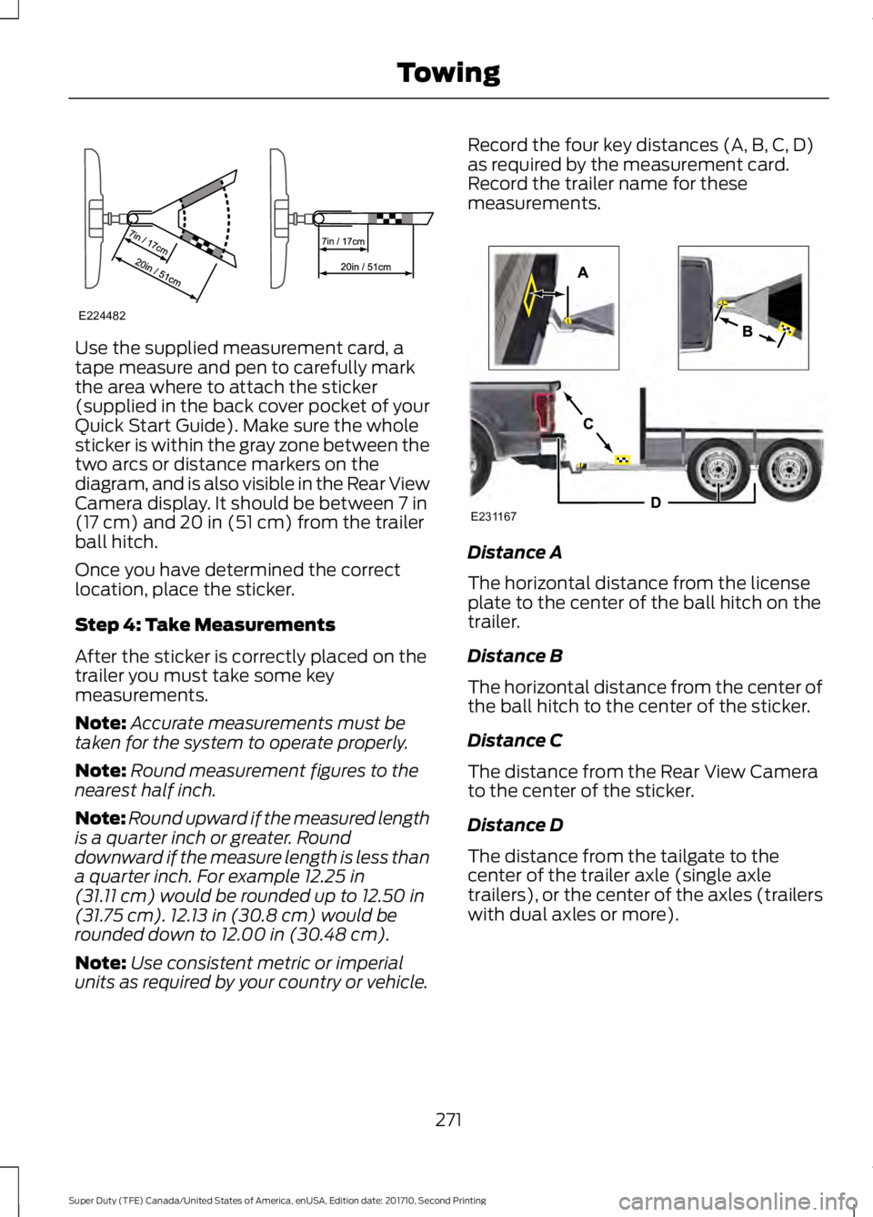
Use the supplied measurement card, atape measure and pen to carefully markthe area where to attach the sticker(supplied in the back cover pocket of yourQuick Start Guide). Make sure the wholesticker is within the gray zone between thetwo arcs or distance markers on thediagram, and is also visible in the Rear ViewCamera display. It should be between 7 in(17 cm) and 20 in (51 cm) from the trailerball hitch.
Once you have determined the correctlocation, place the sticker.
Step 4: Take Measurements
After the sticker is correctly placed on thetrailer you must take some keymeasurements.
Note:Accurate measurements must betaken for the system to operate properly.
Note:Round measurement figures to thenearest half inch.
Note:Round upward if the measured lengthis a quarter inch or greater. Rounddownward if the measure length is less thana quarter inch. For example 12.25 in(31.11 cm) would be rounded up to 12.50 in(31.75 cm). 12.13 in (30.8 cm) would berounded down to 12.00 in (30.48 cm).
Note:Use consistent metric or imperialunits as required by your country or vehicle.
Record the four key distances (A, B, C, D)as required by the measurement card.Record the trailer name for thesemeasurements.
Distance A
The horizontal distance from the licenseplate to the center of the ball hitch on thetrailer.
Distance B
The horizontal distance from the center ofthe ball hitch to the center of the sticker.
Distance C
The distance from the Rear View Camerato the center of the sticker.
Distance D
The distance from the tailgate to thecenter of the trailer axle (single axletrailers), or the center of the axles (trailerswith dual axles or more).
271
Super Duty (TFE) Canada/United States of America, enUSA, Edition date: 201710, Second Printing
TowingE224482 E231167
Page 275 of 642
Step 5: Enter Measurements Using theInformation Display
Using the recorded measurements, enterthe required data into the system. Followthe on screen prompts to enter each of themeasurements taken in step 4. Use theup/down arrows to increase or decreasethe numbers as needed. Press OK toconfirm each measurement. The screenprompts you to add the nextmeasurement. Once you add your lastmeasurement, the information displayshows you all of your enteredmeasurements. You can choose to confirmor change the measurements.
Step 6: Confirming the Sticker Location
Check the Rear View Camera display tosee if the sticker is identified by the systemand marked with a red circle.
Confirm that the red circle is correctlylocated over the sticker image in thedisplay. The on screen prompt will ask youto confirm this.
Note:If the system cannot locate thesticker try cleaning the camera lens, andalso make sure the sticker is within the zoneas indicated in step 3.
The information display shows aconfirmation message when yousuccessfully confirm the target.
Calibrating the System
To complete setup, drive your vehiclestraight forward between 4 mph (6 km/h)and 24 mph (39 km/h) as directed by theinformation display.
Note:Keep the steering wheel straightduring the calibration process. If the steeringwheel is in a turned position, then thecalibration pauses. The information displayprompts you to drive straight forward tocomplete the calibration.
The information display shows a messageduring calibration and after calibration iscomplete
Note:For best results, we do notrecommend that you calibrate the systemat night.
Using Trailer Reverse Guidance
1. Shift into reverse (R) if you are notalready in reverse. Press the rearcamera button to expand the menu.
2. Press the trailer icon .
3. Select your trailer on your informationdisplay.
4. While in TRG mode, you can see thecamera view on the side where yourtrailer is moving, or both sides whenthe trailer is straight behind you. Whenthe views change with the trailerdirection, it's called Auto Mode. Forexample, If you turn the trailer to theright, then you see the right side of yourvehicle and trailer. You can switch thisview manually at any time by using thearrow keys. To return to Auto Mode,press the Auto button.
Note:Auto Mode is your default setting.
Use the view that helps you the most whilebacking up your vehicle and trailer.
Normal rear view camera view.Use this feature when you wantto see your trailer hitch or whatis directly behind your vehicle.
Straight back-up mode. Use thisfeature when you want to keepyour trailer completely in linewith your truck. In this mode, a steeringwheel graphic shows you which way to turnyour steering wheel to keep your trailerstraight.
272
Super Duty (TFE) Canada/United States of America, enUSA, Edition date: 201710, Second Printing
TowingE224483 E224484
Page 276 of 642
Note: It may be helpful to shift your vehicleinto drive (D), pull forward and straightenout the vehicle and trailer before engagingStraight Backup Mode.
Left and right arrows let you see otherviews regardless of your trailer angle. Usethem to switch views manually.
Note: If you're using a Fifth Wheel orGooseneck trailer, or you haven't set up theTrailer Reverse Guidance System yet, AutoView is not available.
To change your view, use the arrows. Youcan see the following views:
•Full driver
•Partial driver
•50/50
•Partial passenger
•Full passenger
Zoom. Use this feature to zoomin on any view.
Return. Ths feature takes youback to the 360-degree camerasystem and out of the TrailerReverse Guidance feature.
Auto. Ths feature returns you toautomatic view mode.
In addition to multiple view options, yourtouchscreen adds some features to giveyou more information.
After using the set up for a conventionaltrailer, for example, the display alwaysshows you a small, top-viewrepresentation of your truck and trailer.
This representation shows two,different-colored lines: A black line showsyou where your trailer is in relation to yourvehicle. A white line gives you a projectionof where your trailer will go based on yourcurrent steering wheel position
Note:When you move the steering wheel,the white line indicates where the trailer willgo based on your steering wheel input.
When you turn your steering wheel to theleft, the trailer moves to the right; when youturn your steering wheel to the right, thetrailer moves to the left.
When you turn the wheel, the smallrepresentation shows you two zones towarn you of a possible jackknife condition.The view shows you your truck and trailerposition and provides visual feedback tohelp you avoid jackknifing entirely.
The yellow zone warns you of a potentialjackknife position. When you enter into thiszone, it's best to put your vehicle back intodrive (D) and pull forward. Moving forwardhelps put the truck and trailer back into anin-line position.
The RED zone indicates that you need toput the truck into drive (D) and pullforward immediately.
Troubleshooting
Note:The system requires a clear view ofthe sticker placed on the trailer. You mustkeep the camera lens and sticker clean forthe system to operate correctly.
Setup
The system is designed to be used with awide variety of trailers. However there aresome trailers that do not have a propersurface and location to mount the sticker.These trailers are not supported. Attemptsto place the sticker on a surface that doesnot meet the sticker placementrequirement listed in Step 3 of the setupinstruction or entering inaccuratemeasurements to proceed through setupcan result in improper system function.
273
Super Duty (TFE) Canada/United States of America, enUSA, Edition date: 201710, Second Printing
TowingE224485 E224487 E224486
Page 277 of 642
Accurate measurements are critical tocorrect system function. If you need tocheck measurements entered or changethem you can access them through thetrailer menus in the information display.Choose the option to change the stickerfrom the change trailer settings menu. It isnot necessary to remove the sticker if youare just reviewing or changingmeasurements.
The following menu warnings or difficultiesmay occur during setup. Tips to resolvethem are listed below.
Measurement A has reached maximum orminimum value:
•The system is designed to work withdrawbars that have a license plate tohitch ball center measurement of 9 in(229 mm) to 16 in (406 mm) wheninstalled. Do not attempt to usedrawbars that have a length outsidethis range as the system performancewill be degraded and could causeimproper system function.
•Make sure that the measurement beingmade is the horizontal distance onlyfrom license plate and the hitch ballcenter. A straight line distance thatincludes any vertical rise or drop willincrease the measurement and makeit inaccurate. Inaccuratemeasurements will degrade systemperformance and could cause impropersystem function. See step 4 of thesetup instruction to reviewmeasurement instructions.
Measurement B has reached maximum orminimum value:
•Make sure that the sticker placementinstruction in step 3 of the setup hasbeen followed. Stickers placed outsidethe allowed zone will adversely affectthe system performance and couldcause improper feature function.
•Make sure that the measurement beingmade is the horizontal distance onlyfrom center of sticker to the hitch ballcenter. A straight line distance thatincludes any vertical rise or drop willincrease the measurement and causean inaccurate value to be entered intothe system. See step 4 of the setup foradditional measurement instructions.
Measurement C has reached maximum orminimum value:
•Make sure that the sticker placementinstructions in step 3 of the setup havebeen followed. Stickers placed outsidethe allowed zone will adversely affectthe system performance and couldcause improper feature function. If youhave met all the criteria for stickerplacement and you see this messagethis sticker is either too far below or tooclose to the camera to properlyrecognize the sticker. In order for thesystem to operate correctly the stickerheight must be lowered if you receivethe minimum warning or the stickerheight must be raised if you receive themaximum warning.
•Only one sticker can be placed onthe trailer for correct systemfunction. The previous sticker mustbe removed or covered so only onesticker is visible to the camera.
•Measurement B and C must bemeasured again if a new sticker isplaced on the trailer.
274
Super Duty (TFE) Canada/United States of America, enUSA, Edition date: 201710, Second Printing
Towing
Page 278 of 642
Measurement D has reached maximum orminimum value:
•Make sure that the measurement beingmade is the horizontal distance onlyfrom tailgate to the center of the singleaxle or the center of all the axles on thetrailer. See step 4 of the setup foradditional measurement instructions.The TBA system does not supporttrailer lengths outside the rangeallowed by the information display.
System is circling something beside thesticker or system cannot find the sticker:
•Make sure the rear camera is clean andthe sticker is clearly visible in thecamera image. Clean the camera andsticker if necessary.
•The camera system uses the enteredmeasurements to help locate thesticker. Inaccurate stickermeasurements will degrade thesystem’s ability to locate the sticker.Verify the measurements entered intothe system are accurate.
•Remove the incorrectly circled label ordecal if possible.
•If you cannot resolve the issue a newsticker location should be tried. Thesticker location must still meet therequirements noted in step 3 of thesetup instructions. Only one sticker canbe placed on the trailer for correctsystem function. The previous stickermust be removed or covered so onlyone sticker is visible to the camera.
Calibration
The system monitors various vehicleparameters to ensure your vehicle is beingdriven straight and the trailer straightbehind your vehicle. Any steering input ortrailer movement will pause the calibration.
For best results:
•Use a long, straight and smooth roadwhen attempting to calibrate.
•Drive straight forward.
•Drive between 4 mph (6 km/h) and24 mph (39 km/h).
System Operation
The following warnings or difficulties mayoccur during feature operation. Tips toresolve them are listed below.
The system is not available:
•The system relies on manysub-systems in your vehicle to operatecorrectly. If those sub-systems are notoperating correctly the system may notbe available.
•Low battery voltage is a conditionwhich will prevent the system fromoperating. Please make sure thebattery is correctly charged if thesystem is not available.
•You may need to drive your vehiclestraight forward above 25 mph(40 km/h) before the system isavailable again.
•If the message still displays take yourvehicle to an authorized dealer forservice.
275
Super Duty (TFE) Canada/United States of America, enUSA, Edition date: 201710, Second Printing
Towing
Page 279 of 642
Sticker lost:
•Check for the following if you receivethe lost sticker message while usingthe system.
•Stop your vehicle as soon as themessage displays.
•Make sure the sticker is visible inthe rear view camera image.
•Clean the sticker and camera tomake sure they are unobstructed.
•Remove any items that may beblocking the view of the sticker.Depending on your trailerconfiguration and any equipmentmounted to your trailer it is possiblefor the sticker to be blocked fromview of the camera as it rotates onthe hitch ball but not be blockedduring setup. Remove theobstruction if possible. It will be
necessary to remove the stickerfrom it’s current location if theobstruction cannot be cleared andplace a new sticker that will bevisible to the camera in all positionsof the trailer behind your vehicle.
•You can change your stickerlocation by going into the trailermenu, selecting trailer options,selecting change trailer settingsand then selecting the changesticker option. The previous stickermust be removed.ONLY ONESTICKER SHOULD BE PLACEDON THE TRAILER FOR CORRECTSYSTEM FUNCTION.
•The camera system uses theentered measurements to helplocate the sticker. Inaccuratemeasurements will reduce thesystem’s ability to locate thesticker. Check the measurementsentered into the system are correct.Refer to the step 4 of TrailerReverse Guidance setup forinstructions on measurements.
•You can change your measurementby going into the trailer menu,selecting trailer options, selectingchange trailer setting and thenselecting the change sticker option.Disregard the prompt to removethis sticker and continue to the nextstep if you only plan to update themeasurements for the currentsticker location.
System will not backup straight:
•Factors such as the drawbarconnection to the hitch receiver, roadcamber, road grade and compliance inthe trailer suspension can influencehow straight the system is able to backyour trailer when the wheel is notturned. You can compensate for thetrailer drifting to the right or left by
276
Super Duty (TFE) Canada/United States of America, enUSA, Edition date: 201710, Second Printing
Towing
Page 280 of 642
slowly turning the wheel until the traileris following your desired path and thenholding the wheel in that position. Ifyou would like to recalibrate thesystem for straight backing, you can doso with the following procedure.
•Go into the trailer menu, selecttrailer options, select change trailersetting and then select the changesticker option. Your savedmeasurements will be displayed.Do not change them but continueto confirm measurements. Onceyou confirm the measurements, thesystem will then prompt you toperform the calibration procedure.
Note:The system is designed to be usedwith the same trailer connection every timethe trailer is chosen from the selectionmenu. Using a different drawbar or adifferent pin hole (on drawbars with morethan one) when connecting the drawbar toyour vehicle will affect the trailermeasurements. Take the measurementsagain and update if required.
TRAILER SWAY CONTROL (If
Equipped)
WARNING
Turning off trailer sway controlincreases the risk of loss of vehiclecontrol, serious injury or death. Forddoes not recommend disabling this featureexcept in situations where speed reductionmay be detrimental (such as hill climbing),the driver has significant trailer towingexperience, and can control trailer swayand maintain safe operation.
Note:This feature does not prevent trailersway, but reduces it once it begins.
Note:This feature cannot stop all trailersfrom swaying.
Note:In some cases, if vehicle speed is toohigh, the system may activate multipletimes, gradually reducing vehicle speed.
This feature applies your vehicle brakes atindividual wheels and, if necessary, reducesengine power. If the trailer begins to sway,the stability control light flashes and themessage TRAILER SWAY REDUCESPEED appears in the information display.The first thing to do is slow your vehicledown, then pull safely to the side of theroad and check for proper tongue load andtrailer load distribution. See LoadCarrying (page 261).
RECOMMENDED TOWING
WEIGHTS
WARNING
You must use the heavy-dutydrawbar pin supplied with
your vehicle when using theheavy-duty hitch. Failure to followthis instruction could result in theloss of control of your vehicle,personal injury or death.
Note:Vehicles with a heavy-dutyhitch must use the drawbar pinstamped 21,000 LBS. You canobtain a replacement drawbar pinat your Ford dealer.
Note:Make sure to take intoconsideration trailer frontal area.Do not exceed 60 feet2 (5.6
meters2) trailer frontal area for
conventional trailers. Do notexceed 75 feet2 (6.9 meters2) trailer
frontal area for 5th wheel andgooseneck trailers.
277
Super Duty (TFE) Canada/United States of America, enUSA, Edition date: 201710, Second Printing
Towing