fuse FORD F350 2001 Owners Manual
[x] Cancel search | Manufacturer: FORD, Model Year: 2001, Model line: F350, Model: FORD F350 2001Pages: 288, PDF Size: 2.07 MB
Page 6 of 288
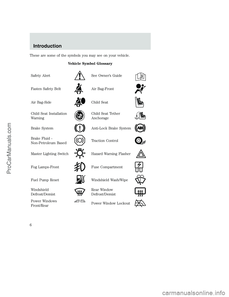
These are some of the symbols you may see on your vehicle.
Vehicle Symbol Glossary
Safety Alert
See Owner’s Guide
Fasten Safety BeltAir Bag-Front
Air Bag-SideChild Seat
Child Seat Installation
WarningChild Seat Tether
Anchorage
Brake SystemAnti-Lock Brake System
Brake Fluid -
Non-Petroleum BasedTraction Control
Master Lighting SwitchHazard Warning Flasher
Fog Lamps-FrontFuse Compartment
Fuel Pump ResetWindshield Wash/Wipe
Windshield
Defrost/DemistRear Window
Defrost/Demist
Power Windows
Front/RearPower Window Lockout
Introduction
6
ProCarManuals.com
Page 108 of 288
Always transport children 12 years old and under in the back
seat and always properly use appropriate child restraints.
National Highway Traffic Safety Administration (NHTSA)
recommends a minimum distance of at least 25 cm (10 inches)
between an occupant’s chest and the driver air bag module.
Never place your arm over the air bag module as a deploying air
bag can result in serious arm fractures or other injuries.
Steps you can take to properly position yourself away from the air bag:
•Move your seat to the rear as far as you can while still reaching the
pedals comfortably.
•Recline the seat slightly (one or two degrees) from the upright
position.
Do not put anything on or over the air bag module. Placing
objects on or over the air bag inflation area may cause those
objects to be propelled by the air bag into your face and torso causing
serious injury.
Do not attempt to service, repair, or modify the air bag
supplemental restraint systems or its fuses. Se your Ford or
Lincoln Mercury dealer.
Modifications to the front end of the vehicle, including frame,
bumper, front end body structure and tow hooks may affect the
performance of the air bag sensors increasing the risk of injury. Do not
modify the front end of the vehicle.
Additional equipment such as snowplow equipment may effect
the performance of the air bag sensors increasing the risk of
injury. Please refer to the Body Builders Layout Book for instructions
about the appropriate installation of additional equipment.
Seating and safety restraints
108
ProCarManuals.com
Page 136 of 288
AUTOMATIC TRANSMISSION OPERATION (IF EQUIPPED)
Brake-shift interlock
This vehicle is equipped with a brake-shift interlock feature that prevents
the gearshift lever from being moved from P (Park) when the ignition is
in the ON position unless brake pedal is depressed.
If you cannot move the gearshift lever out of P (Park) with ignition in
the ON position and the brake pedal depressed:
1. Apply the parking brake, turn ignition to the LOCK position, then
remove the key.
2. Reinsert the key and turn the ignition to the OFF position.
3. Press and hold down the brake pedal and shift into N (Neutral).
4. Start the vehicle.
If it is necessary to use the above procedure to move the gearshift lever,
it is possible that a fuse has blown or the vehicle’s brakelamps are not
operating properly. Refer toFuses and relaysin theRoadside
emergencieschapter.
Do not drive your vehicle until you verify that the brakelamps
are working.
If your vehicle gets stuck in mud or snow it may be rocked out by
shifting from forward and reverse gears, stopping between shifts, in a
steady pattern. Press lightly on the accelerator in each gear.
Do not rock the vehicle for more than a few minutes. The
transmission and tires may be damaged or the engine may
overheat.
Always set the parking brake fully and make sure the gearshift is
latched in P (Park). Turn off the ignition whenever you leave
your vehicle.
If the parking brake is fully released, but the brake warning lamp
remains illuminated, the brakes may not be working properly.
See your dealer or a qualified service technician.
Driving
136
ProCarManuals.com
Page 162 of 288
Trailer towing tips
•Practice turning, stopping and backing up before starting on a trip to
get the feel of the vehicle trailer combination. When turning, make
wider turns so the trailer wheels will clear curbs and other obstacles.
•Allow more distance for stopping with a trailer attached.
•The trailer tongue weight should be no more than 10–15% of the
loaded trailer weight.
•After you have traveled 80 km (50 miles), thoroughly check your
hitch, electrical connections and trailer wheel lug nuts.
•When stopped in traffic for long periods of time in hot weather, place
the gearshift in P (Park) (automatic transmissions) or N (Neutral)
(manual transmissions). This aids engine cooling and air conditioner
efficiency.
•Vehicles with trailers should not be parked on a grade. If you must
park on a grade, place wheel chocks under the trailer’s wheels.
Launching or retrieving a boat
When backing down a ramp during boat launching or retrieval,
•Do not allow the static water level to rise above the bottom edge of
the rear bumper and
•Do not allow waves to break higher than 15 cm (6 inches) above the
bottom edge of the rear bumper.
•Disconnect the trailer tow electrical connector to prevent blown fuses
caused by water entering into your trailer’s electrical wiring.
Exceeding these limits may allow water to enter critical vehicle
components, adversely affecting driveability, emissions and reliability.
Replace front and rear axle lubricants any time the axles have been
submerged in water. Axle lubricant quantities are not to be checked
unless a leak is suspected.
All Rear Wheel Drive (RWD) vehicles
This applies to all cars and 4x2 trucks/sport utilities with rear wheel
drive capability.
An example of recreational towing is towing your vehicle behind a
motorhome. The following recreational towing guidelines are designed to
ensure that your transmission is not damaged.
Driving
162
ProCarManuals.com
Page 165 of 288
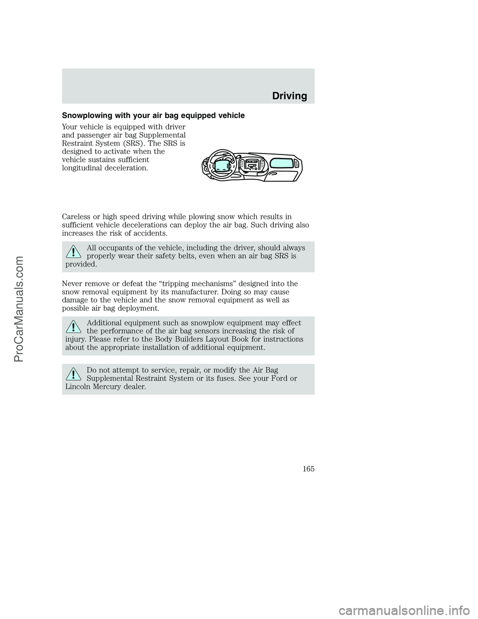
Snowplowing with your air bag equipped vehicle
Your vehicle is equipped with driver
and passenger air bag Supplemental
Restraint System (SRS). The SRS is
designed to activate when the
vehicle sustains sufficient
longitudinal deceleration.
Careless or high speed driving while plowing snow which results in
sufficient vehicle decelerations can deploy the air bag. Such driving also
increases the risk of accidents.
All occupants of the vehicle, including the driver, should always
properly wear their safety belts, even when an air bag SRS is
provided.
Never remove or defeat the “tripping mechanisms” designed into the
snow removal equipment by its manufacturer. Doing so may cause
damage to the vehicle and the snow removal equipment as well as
possible air bag deployment.
Additional equipment such as snowplow equipment may effect
the performance of the air bag sensors increasing the risk of
injury. Please refer to the Body Builders Layout Book for instructions
about the appropriate installation of additional equipment.
Do not attempt to service, repair, or modify the Air Bag
Supplemental Restraint System or its fuses. See your Ford or
Lincoln Mercury dealer.
Driving
165
ProCarManuals.com
Page 170 of 288
FUSES AND RELAYS
Fuses
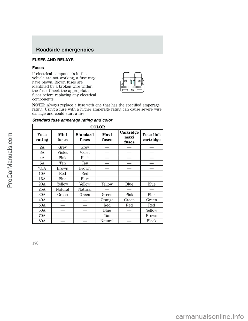
If electrical components in the
vehicle are not working, a fuse may
have blown. Blown fuses are
identified by a broken wire within
the fuse. Check the appropriate
fuses before replacing any electrical
components.
NOTE:Always replace a fuse with one that has the specified amperage
rating. Using a fuse with a higher amperage rating can cause severe wire
damage and could start a fire.
Standard fuse amperage rating and color
COLOR
Fuse
ratingMini
fusesStandard
fusesMaxi
fusesCartridge
maxi
fusesFuse link
cartridge
2A Grey Grey — — —
3A Violet Violet — — —
4A Pink Pink — — —
5A Tan Tan — — —
7.5A Brown Brown — — —
10A Red Red — — —
15A Blue Blue — — —
20A Yellow Yellow Yellow Blue Blue
25A Natural Natural — — —
30A Green Green Green Pink Pink
40A — — Orange Green Green
50A — — Red Red Red
60A — — Blue — Yellow
70A — — Tan — Brown
80A — — Natural — Black
15
Roadside emergencies
170
ProCarManuals.com
Page 171 of 288
Passenger compartment fuse panel
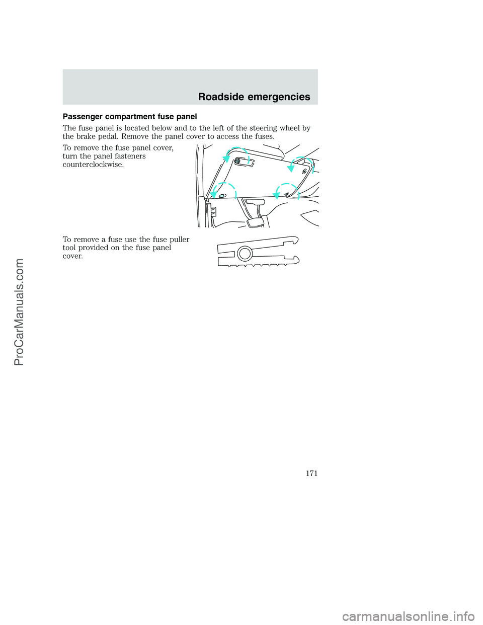
The fuse panel is located below and to the left of the steering wheel by
the brake pedal. Remove the panel cover to access the fuses.
To remove the fuse panel cover,
turn the panel fasteners
counterclockwise.
To remove a fuse use the fuse puller
tool provided on the fuse panel
cover.
Roadside emergencies
171
ProCarManuals.com
Page 172 of 288
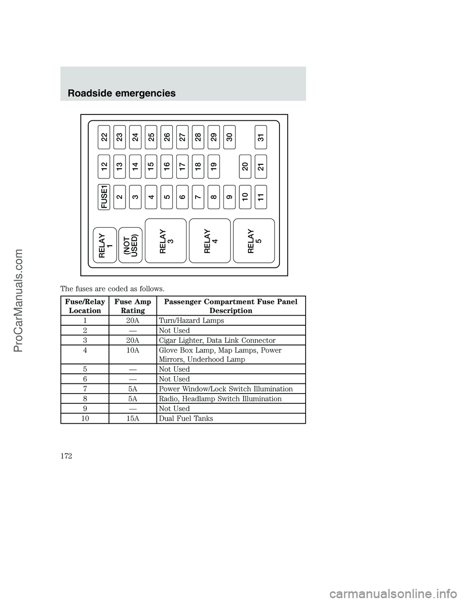
The fuses are coded as follows.
Fuse/Relay
LocationFuse Amp
RatingPassenger Compartment Fuse Panel
Description
1 20A Turn/Hazard Lamps
2 — Not Used
3 20A Cigar Lighter, Data Link Connector
4 10A Glove Box Lamp, Map Lamps, Power
Mirrors, Underhood Lamp
5 — Not Used
6 — Not Used
7 5A Power Window/Lock Switch Illumination
8 5A Radio, Headlamp Switch Illumination
9 — Not Used
10 15A Dual Fuel Tanks
FUSE1 RELAY
1
RELAY
3 (NOT
USED)
RELAY
4
RELAY
512 22
21323
31424
4
16 15
25
526
61727
71828
81929
11 21 31930
10 20
Roadside emergencies
172
ProCarManuals.com
Page 173 of 288
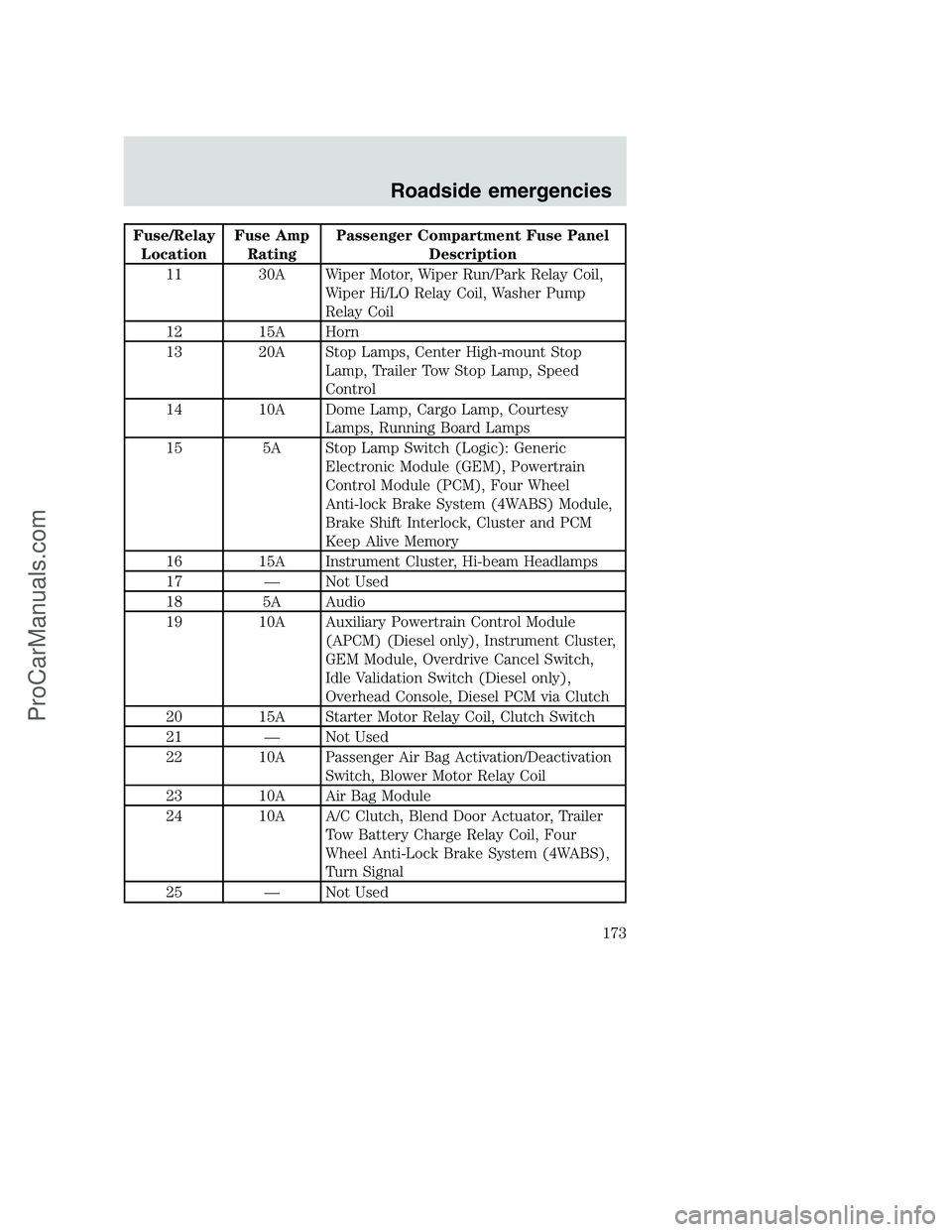
Fuse/Relay
LocationFuse Amp
RatingPassenger Compartment Fuse Panel
Description
11 30A Wiper Motor, Wiper Run/Park Relay Coil,
Wiper Hi/LO Relay Coil, Washer Pump
Relay Coil
12 15A Horn
13 20A Stop Lamps, Center High-mount Stop
Lamp, Trailer Tow Stop Lamp, Speed
Control
14 10A Dome Lamp, Cargo Lamp, Courtesy
Lamps, Running Board Lamps
15 5A Stop Lamp Switch (Logic): Generic
Electronic Module (GEM), Powertrain
Control Module (PCM), Four Wheel
Anti-lock Brake System (4WABS) Module,
Brake Shift Interlock, Cluster and PCM
Keep Alive Memory
16 15A Instrument Cluster, Hi-beam Headlamps
17 — Not Used
18 5A Audio
19 10A Auxiliary Powertrain Control Module
(APCM) (Diesel only), Instrument Cluster,
GEM Module, Overdrive Cancel Switch,
Idle Validation Switch (Diesel only),
Overhead Console, Diesel PCM via Clutch
20 15A Starter Motor Relay Coil, Clutch Switch
21 — Not Used
22 10A Passenger Air Bag Activation/Deactivation
Switch, Blower Motor Relay Coil
23 10A Air Bag Module
24 10A A/C Clutch, Blend Door Actuator, Trailer
Tow Battery Charge Relay Coil, Four
Wheel Anti-Lock Brake System (4WABS),
Turn Signal
25 — Not Used
Roadside emergencies
173
ProCarManuals.com
Page 174 of 288
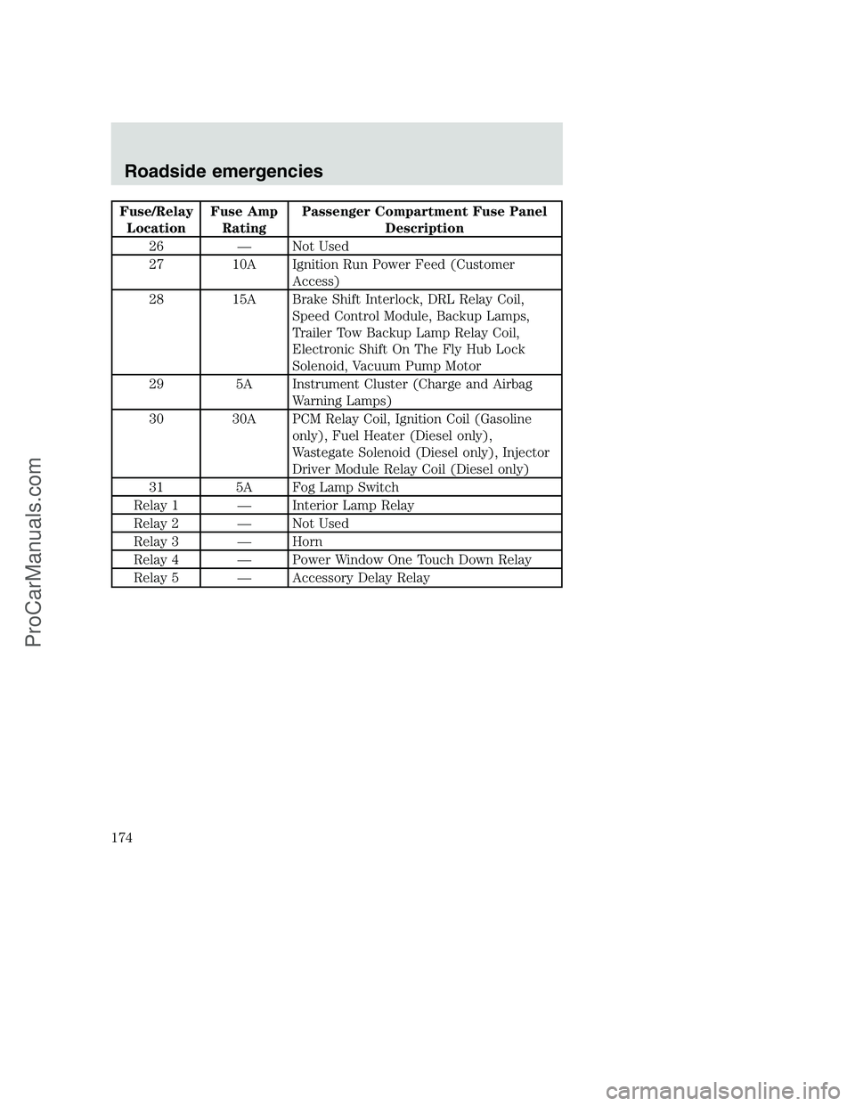
Fuse/Relay
LocationFuse Amp
RatingPassenger Compartment Fuse Panel
Description
26 — Not Used
27 10A Ignition Run Power Feed (Customer
Access)
28 15A Brake Shift Interlock, DRL Relay Coil,
Speed Control Module, Backup Lamps,
Trailer Tow Backup Lamp Relay Coil,
Electronic Shift On The Fly Hub Lock
Solenoid, Vacuum Pump Motor
29 5A Instrument Cluster (Charge and Airbag
Warning Lamps)
30 30A PCM Relay Coil, Ignition Coil (Gasoline
only), Fuel Heater (Diesel only),
Wastegate Solenoid (Diesel only), Injector
Driver Module Relay Coil (Diesel only)
31 5A Fog Lamp Switch
Relay 1 — Interior Lamp Relay
Relay 2 — Not Used
Relay 3 — Horn
Relay 4 — Power Window One Touch Down Relay
Relay 5 — Accessory Delay Relay
Roadside emergencies
174
ProCarManuals.com