lock FORD F650 2002 10.G Owner's Manual
[x] Cancel search | Manufacturer: FORD, Model Year: 2002, Model line: F650, Model: FORD F650 2002 10.GPages: 256, PDF Size: 1.75 MB
Page 87 of 256
Programming remote transmitters
It is necessary to haveall(maximum of four Ð original and/or new) of
your remote transmitters available prior to beginning this procedure.
To program the transmitters yourself:
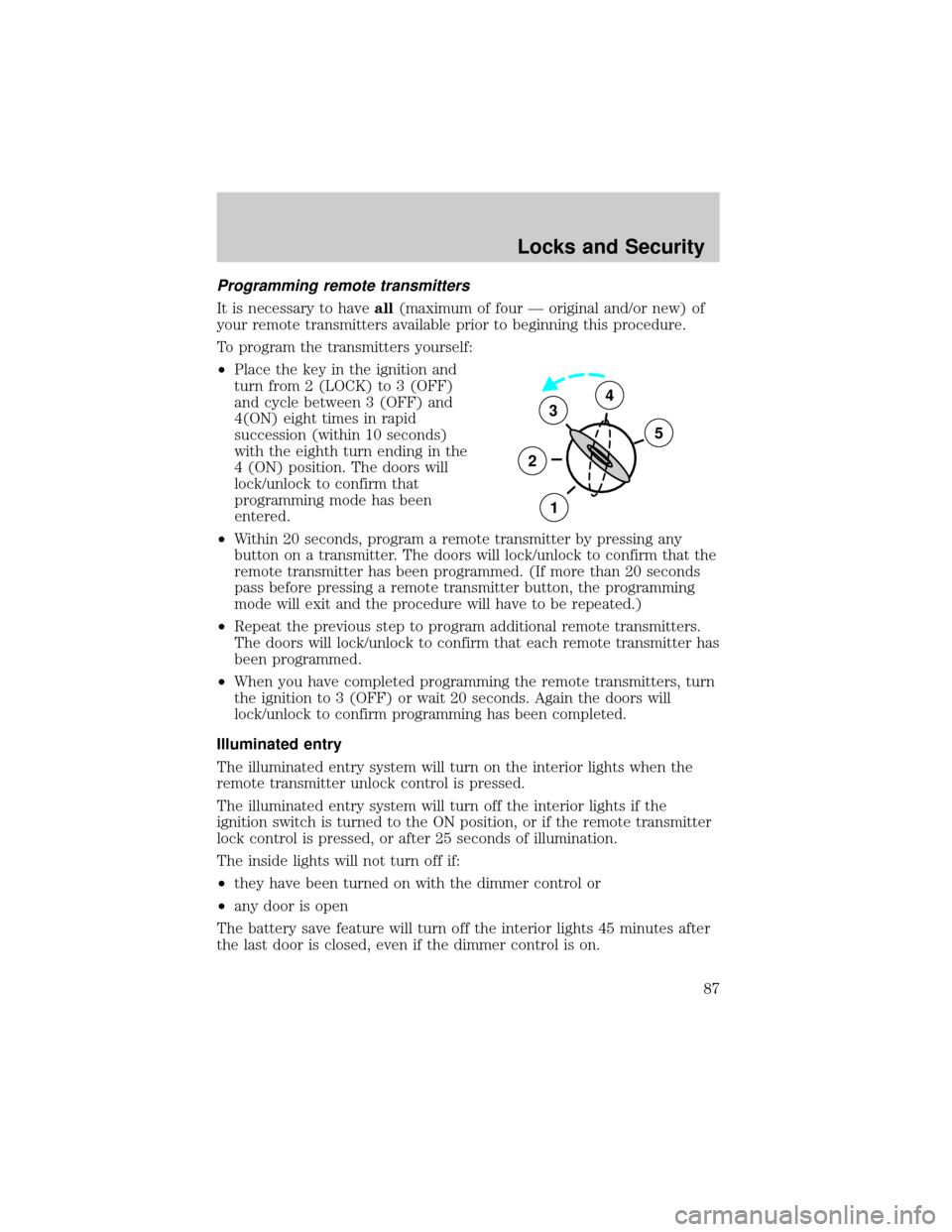
²Place the key in the ignition and
turn from 2 (LOCK) to 3 (OFF)
and cycle between 3 (OFF) and
4(ON) eight times in rapid
succession (within 10 seconds)
with the eighth turn ending in the
4 (ON) position. The doors will
lock/unlock to confirm that
programming mode has been
entered.
²Within 20 seconds, program a remote transmitter by pressing any
button on a transmitter. The doors will lock/unlock to confirm that the
remote transmitter has been programmed. (If more than 20 seconds
pass before pressing a remote transmitter button, the programming
mode will exit and the procedure will have to be repeated.)
²Repeat the previous step to program additional remote transmitters.
The doors will lock/unlock to confirm that each remote transmitter has
been programmed.
²When you have completed programming the remote transmitters, turn
the ignition to 3 (OFF) or wait 20 seconds. Again the doors will
lock/unlock to confirm programming has been completed.
Illuminated entry
The illuminated entry system will turn on the interior lights when the
remote transmitter unlock control is pressed.
The illuminated entry system will turn off the interior lights if the
ignition switch is turned to the ON position, or if the remote transmitter
lock control is pressed, or after 25 seconds of illumination.
The inside lights will not turn off if:
²they have been turned on with the dimmer control or
²any door is open
The battery save feature will turn off the interior lights 45 minutes after
the last door is closed, even if the dimmer control is on.
3
2
1
5
4
Locks and Security
87
Page 94 of 256

Each seating position in your vehicle has a specific safety belt
assembly which is made up of one buckle and one tongue that
are designed to be used as a pair. 1) Use the shoulder belt on the
outside shoulder only. Never wear the shoulder belt under the arm. 2)
Never swing the safety belt around your neck over the inside shoulder.
3) Never use a single belt for more than one person.
Combination lap and shoulder belts
1. Insert the belt tongue into the
proper buckle (the buckle closest to
the direction the tongue is coming
from) until you hear a snap and feel
it latch. Make sure the tongue is
securely fastened in the buckle.
2. To unfasten, push the release
button and remove the tongue from
the buckle.
The front and rear outboard safety restraints in the vehicle are
combination lap and shoulder belts. The front and rear seat passenger
outboard safety belts have vehicle sensitive emergency locking retractors.
Seating and Safety Restraints
94
Page 95 of 256

Vehicle sensitive retractor
The vehicle sensitive retractor allows free shoulder belt length
adjustment to your movements and locks in response to vehicle
movement. For example, if the driver brakes suddenly or turns a corner
sharply, or the vehicle receives an impact of approximately 8 km/h (5
mph) or more, the combination safety belts will lock to help reduce
forward movement of the driver and passengers.
Front safety belt height adjustment
SuperCab and CrewCab vehicle has safety belt height adjustments for
the driver and front passenger. Adjust the height of the shoulder belt so
the belt rests across the middle of your shoulder.
²4±door SuperCab
Seating and Safety Restraints
95
Page 96 of 256

²4±door CrewCab
To lower the shoulder belt height, push the button and slide the height
adjuster down. To raise the height of the shoulder belt, slide the height
adjuster up. Pull down on the height adjuster to make sure it is locked in
place.
Position the shoulder belt height adjusters so that the belt rests
across the middle of your shoulder. Failure to adjust the safety
belt properly could reduce the effectiveness of the seat belt and
increase the risk of injury in a collision.
Seating and Safety Restraints
96
Page 106 of 256
3. Buckle the seat belt. Push down
on the childseat and pull on the
shoulder portion of the belt to snug
the lap belt. Hold the lap and
shoulder belts next to the tongue
and unbuckle the belt.
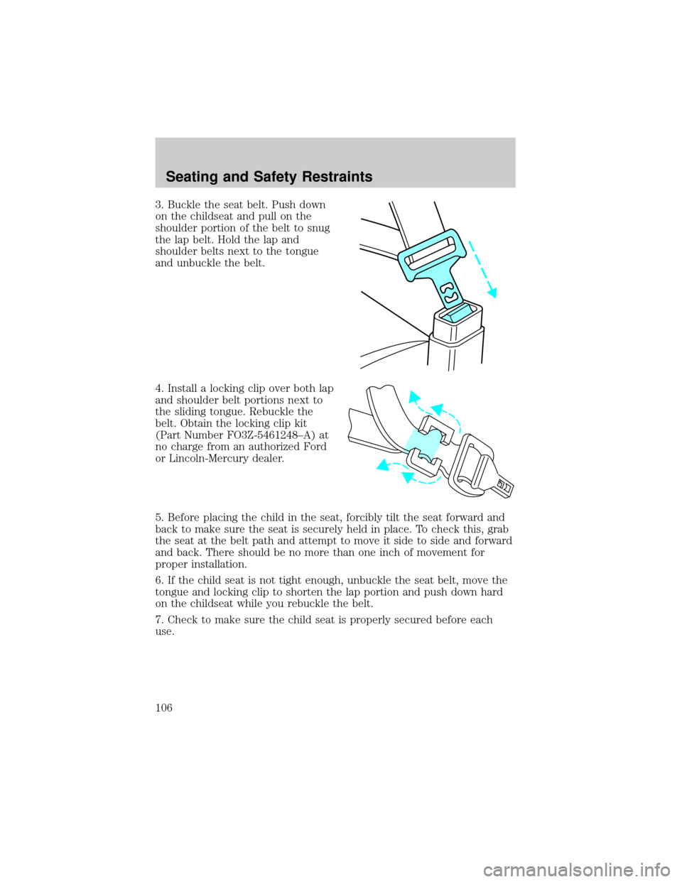
4. Install a locking clip over both lap
and shoulder belt portions next to
the sliding tongue. Rebuckle the
belt. Obtain the locking clip kit
(Part Number FO3Z-5461248±A) at
no charge from an authorized Ford
or Lincoln-Mercury dealer.
5. Before placing the child in the seat, forcibly tilt the seat forward and
back to make sure the seat is securely held in place. To check this, grab
the seat at the belt path and attempt to move it side to side and forward
and back. There should be no more than one inch of movement for
proper installation.
6. If the child seat is not tight enough, unbuckle the seat belt, move the
tongue and locking clip to shorten the lap portion and push down hard
on the childseat while you rebuckle the belt.
7. Check to make sure the child seat is properly secured before each
use.
Seating and Safety Restraints
106
Page 110 of 256
Using the engine block heater (if equipped)
An engine block heater warms the engine coolant, which improves
starting, warms up the engine faster and allows the heater-defroster
system to respond quickly. Use of an engine block heater is strongly
recommended if you live in a region where temperatures reach -23É C
(-10É F) or below.
For best results, plug the heater in at least three hours before starting
the vehicle. Using the heater for longer than three hours will not harm
the engine, so the heater can be plugged in the night before starting the
vehicle.
To prevent electrical shock, do not use your heater with
ungrounded electrical systems or two-pronged (cheater)
adapters.
Operating the engine
Do not operate the engine at full throttle below peak torque engine
speed (RPM) for more than one minute at a time (peak torque RPM
varies from 1200-1500 RPM depending on engine rated speed).
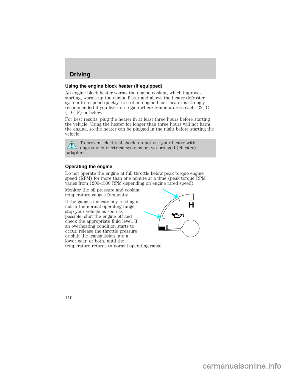
Monitor the oil pressure and coolant
temperature gauges frequently.
If the gauges indicate any reading is
not in the normal operating range,
stop your vehicle as soon as
possible, shut the engine off and
check the appropriate fluid level. If
an overheating condition starts to
occur, release the throttle pressure
or shift the transmission into a
lower gear, or both, until the
temperature returns to normal operating range.
L
H
Driving
110
Page 114 of 256
If the red BRAKE warning lamp in
the instrument cluster remains
illuminated after engine start up,
this indicates a system failure in the
master cylinder of the brake system.
Stop the vehicle safely as soon as possible and seek service immediately.
If the yellow BRAKE RESERVE
(E-motor) warning light remains on
while the engine is running, this
indicates inadequate hydraulic
booster pressure or reserve pump
system failure. Stop the vehicle safely as soon as possible and seek
service immediately.
Four-wheel anti-lock brake system (ABS) (if equipped)
On vehicles equipped with an anti-lock braking system (ABS), a noise
from the hydraulic pump motor and pulsation in the pedal may be
observed during ABS braking events. Pedal pulsation coupled with noise
while braking under panic conditions or on loose gravel, bumps, wet or
snowy roads is normal and indicates proper functioning of the vehicle's
anti-lock brake system. If the vehicle has continuous vibration or shudder
in the steering wheel while braking, the vehicle should be inspected by a
qualified service technician.
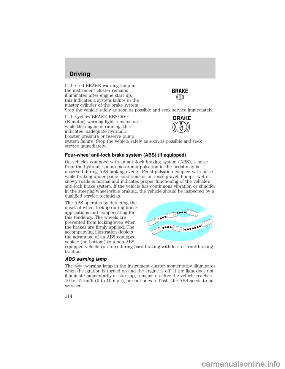
The ABS operates by detecting the
onset of wheel lockup during brake
applications and compensating for
this tendency. The wheels are
prevented from locking even when
the brakes are firmly applied. The
accompanying illustration depicts
the advantage of an ABS equipped
vehicle (on bottom) to a non-ABS
equipped vehicle (on top) during hard braking with loss of front braking
traction.
ABS warning lamp
TheABSwarning lamp in the instrument cluster momentarily illuminates
when the ignition is turned on and the engine is off. If the light does not
illuminate momentarily at start up, remains on after the vehicle reaches
10 to 15 km/h (5 to 10 mph), or continues to flash, the ABS needs to be
serviced.
!
BRAKE
BRAKE
Driving
114
Page 115 of 256
With the ABS light on, the anti-lock brake system is disabled and normal
braking is still effective unless the brake warning light also remains
illuminated. (If your parking brake warning lamp illuminates, have your
vehicle serviced immediately).
Using ABS
²In an emergency or when maximum efficiency from the ABS is
required, apply continuous full force on the brake. The ABS will be
activated immediately, thus allowing you to retain full steering control
of your vehicle and, providing there is sufficient space, will enable you
to avoid obstacles and bring the vehicle to a controlled stop.
²The Anti-Lock system does not decrease the time necessary to apply
the brakes or always reduce stopping distance. Always leave enough
room between your vehicle and the vehicle in front of you to stop.
²We recommend that you familiarize yourself with this braking
technique. However, avoid taking any unnecessary risks.
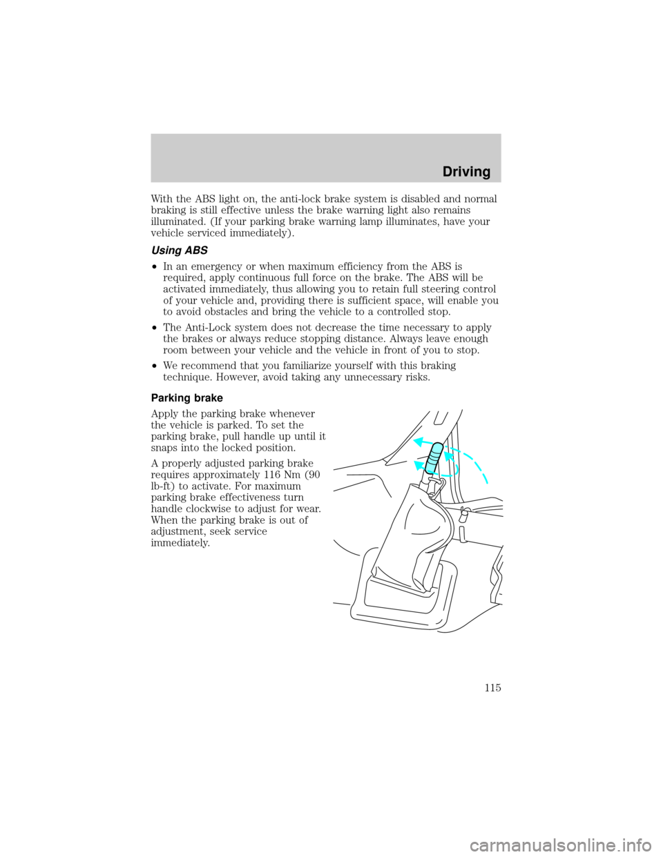
Parking brake
Apply the parking brake whenever
the vehicle is parked. To set the
parking brake, pull handle up until it
snaps into the locked position.
A properly adjusted parking brake
requires approximately 116 Nm (90
lb-ft) to activate. For maximum
parking brake effectiveness turn
handle clockwise to adjust for wear.
When the parking brake is out of
adjustment, seek service
immediately.
Driving
115
Page 118 of 256

Releasing spring brake manually Ð F650 SuperCrewzer
Do not attempt to disassemble the parking brake chamber under
any circumstances. The high spring load may cause serious
injury if the chamber clamps are removed.
If air pressure is released from the spring brake chamber the power
spring applies the brake and, unless air pressure can be re-established,
the spring brake must be released as follows in order to move the
vehicle.
Block the wheels to prevent the vehicle from moving.
Unexpected and possibly sudden vehicle movement may occur if
these precautions are not taken.
Remove the clevis which is attached
to the end of the spring chamber
rod. This can be done by using a
wrench on the flats of the rod to
thread it out of the clevis. There is
sufficient thread length in the clevis
to fully release the parking brake.
Burnish procedure Ð All except F650 SuperCrewzer
For optimal performance of a new parking brake system/new linings
perform the following procedure:
1. While driving the vehicle at 40 km/h (20 mph) apply the parking brake
(with applicable force to set to approximately 18kg [40 lbs.]). Allow the
vehicle to come to a complete stop.
2. Release the parking brake, drive 16.8 km (1.5 miles) to cool the
brakes.
3. Repeat steps 1 through 2 ten times.
Driving
118
Page 121 of 256

repair. The orange stripe is painted on the air chamber push rod at the
slack adjuster readjustment stroke dimension.
Air brake inspection and adjustment should be performed by a qualified
service technician in accordance with the instructions in the Ford Truck
Service Manual.
Cam brakesÐautomatic slack adjusters
Standard air brakes (cam) are
equipped with automatic brake
adjusters. Automatic adjustment
occurs during forward and reverse
brake applications. Inspect brakes
for proper adjustment at the
intervals listed in the vehicle Service
Maintenance Guide.
Emergency air brake
All vehicles are equipped with a dual brake system. In the unlikely event
of a failure of one system, the second system will function for emergency
stopping. These systems are all controlled by the brake pedal in the
same manner as for normal stops.
Do not continue to operate the vehicle with a failure of one of
the systems. Take the vehicle to your dealer for service
immediately.
Anti-lock braking system (if equipped)
For information on the anti-lock braking system (ABS), refer to
Hydraulic brakesin this chapter.
Driving with ABS
Maintain a steady brake pedal application; you do not need to pump or
remove your foot from the pedal. The ABS keeps the wheels rolling
Driving
121