FORD F650 2005 11.G Owners Manual
Manufacturer: FORD, Model Year: 2005, Model line: F650, Model: FORD F650 2005 11.GPages: 272, PDF Size: 1.5 MB
Page 141 of 272
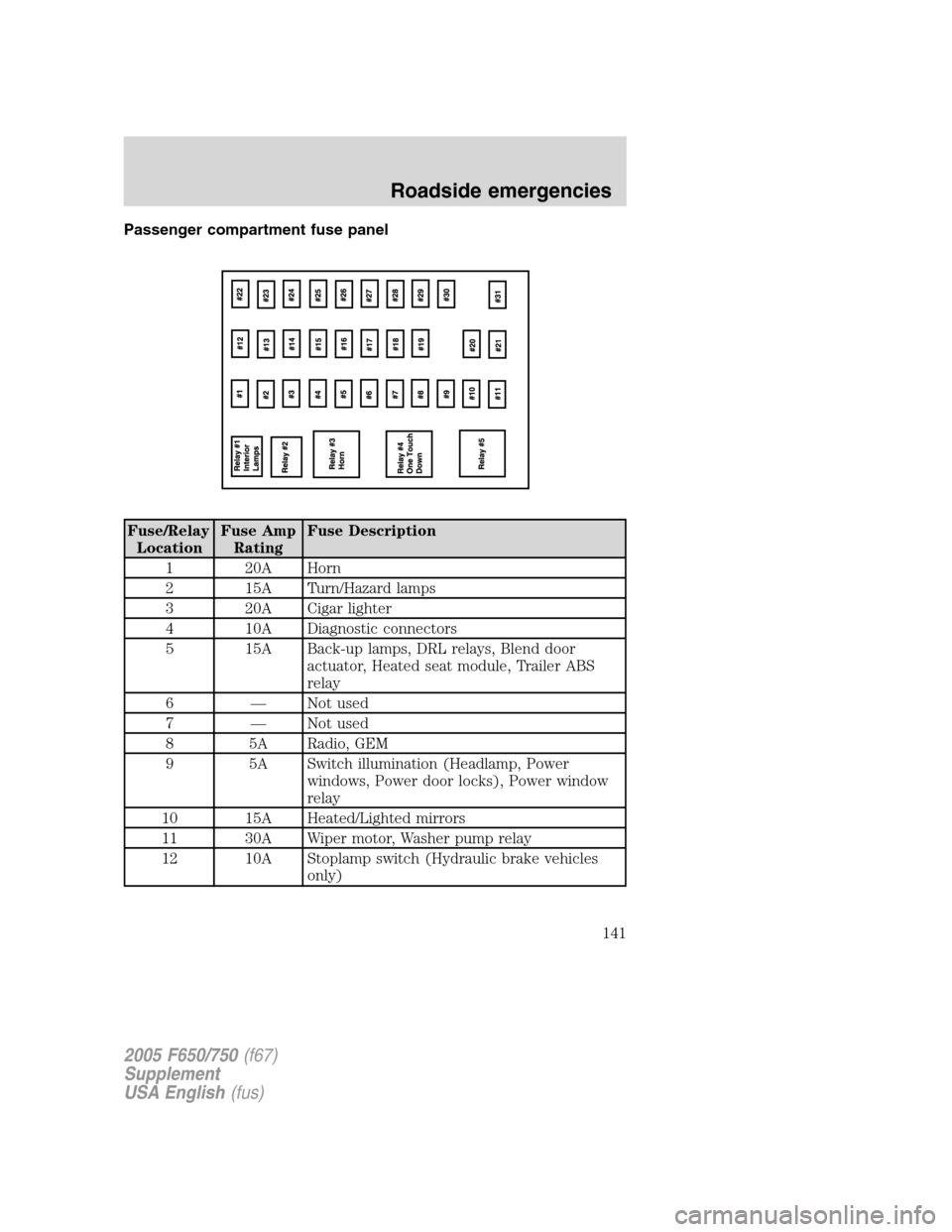
Passenger compartment fuse panel
Fuse/Relay
LocationFuse Amp
RatingFuse Description
1 20A Horn
2 15A Turn/Hazard lamps
3 20A Cigar lighter
4 10A Diagnostic connectors
5 15A Back-up lamps, DRL relays, Blend door
actuator, Heated seat module, Trailer ABS
relay
6—Not used
7—Not used
8 5A Radio, GEM
9 5A Switch illumination (Headlamp, Power
windows, Power door locks), Power window
relay
10 15A Heated/Lighted mirrors
11 30A Wiper motor, Washer pump relay
12 10A Stoplamp switch (Hydraulic brake vehicles
only)
2005 F650/750(f67)
Supplement
USA English(fus)
Roadside emergencies
141
Page 142 of 272
Fuse/Relay
LocationFuse Amp
RatingFuse Description
13 20A Radio, Cluster
14 10A Interior lamps
15 10A GEM, Interior lamp relay, Map lamps
16 15A High beams
17—Not used
18 5A Headlamp switch, GEM
19 15A Engine ECM (Caterpillar and Cummins
engines)
Engine ECM, Accel, Crank (6.0L Power
Stroke engine only)
20 15A Starter relay, GEM
21 10A Daytime Running Lamps (DRL)
22 15A Air solenoid 4–pack (Air horn, Air suspension
dump, Differential lock axle and Two-speed
axle)
23 10A Electronic flasher
24 15A Vacuum pump, Air dryer, ABS, Fuel
heater/Fuel transfer pump relay, Heated
drain valve, 6.0L Power Stroke Water In Fuel
(WIF) module
25 10A Blower motor relay
26 10A RH low beam headlamp
27—Not used
28 10A LH low beam headlamp
29 10A Cluster (Power, Warning lamps), Hydraulic
ABS relay, Air traction control
30 30A Not used
31 15A Allison transmissions
Relay 1—Interior lamps
Relay 2—Not used
Relay 3—Horn
Relay 4—One-touch down window
Relay 5—Not used
2005 F650/750(f67)
Supplement
USA English(fus)
Roadside emergencies
142
Page 143 of 272
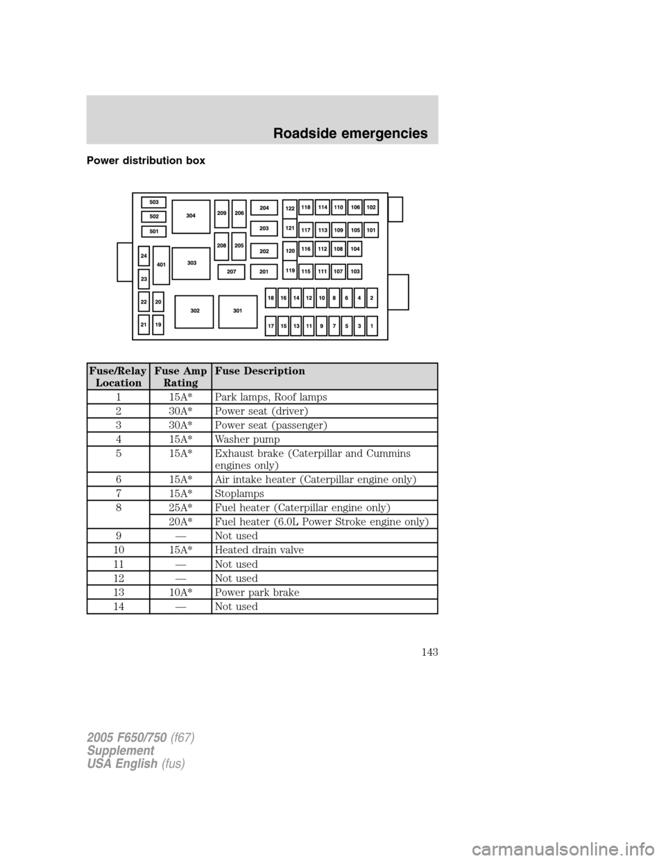
Power distribution box
Fuse/Relay
LocationFuse Amp
RatingFuse Description
1 15A* Park lamps, Roof lamps
2 30A* Power seat (driver)
3 30A* Power seat (passenger)
4 15A* Washer pump
5 15A* Exhaust brake (Caterpillar and Cummins
engines only)
6 15A* Air intake heater (Caterpillar engine only)
7 15A* Stoplamps
8 25A* Fuel heater (Caterpillar engine only)
20A* Fuel heater (6.0L Power Stroke engine only)
9—Not used
10 15A* Heated drain valve
11—Not used
12—Not used
13 10A* Power park brake
14—Not used
2005 F650/750(f67)
Supplement
USA English(fus)
Roadside emergencies
143
Page 144 of 272
Fuse/Relay
LocationFuse Amp
RatingFuse Description
15 7.5A* Body builder prep/trailer socket stop (6.0L
Power Stroke engine only)
16 5A* WABCO hydraulic ABS Run feed
17—Not used
18 10A* Fuel transfer pump (duel fuel tanks only)
19—Not used
20 10A* Engine ECM power relay (6.0L Power Stroke
engine only)
21 10A* GEM (Hydraulic brake vehicles only)
22 10A* Engine IDM2 logic power (6.0L Power Stroke
engine only)
23—Not used
24—Not used
101 30A** Bendix Air ABS relay (Air brake vehicles
only)
WABCO ABS modulator relay (Hydraulic
brake vehicles only)
102 20A** Body builder prep Run feed
103 50A** Ignition switch (Junction box fuses 8, 9, 10,
11, 19, 20, 22, 23, 24, 25, 29, 30, 31)
104 20A** Power point
105 20A** Power door locks
106 30A** Headlamps
107 50A** Junction box battery feed (1, 2, 3, 4, 12, 13,
14, 15)
108 40A** Fuel heater (Cummins engine only)
109 40A** Power windows
110—Not used
111 30A** Body builder prep
112 40A** Blower motor
113 30A** Heated seat (passenger side)
114 25A** WABCO ABS battery feed (Hydraulic brake
vehicles only)
2005 F650/750(f67)
Supplement
USA English(fus)
Roadside emergencies
144
Page 145 of 272
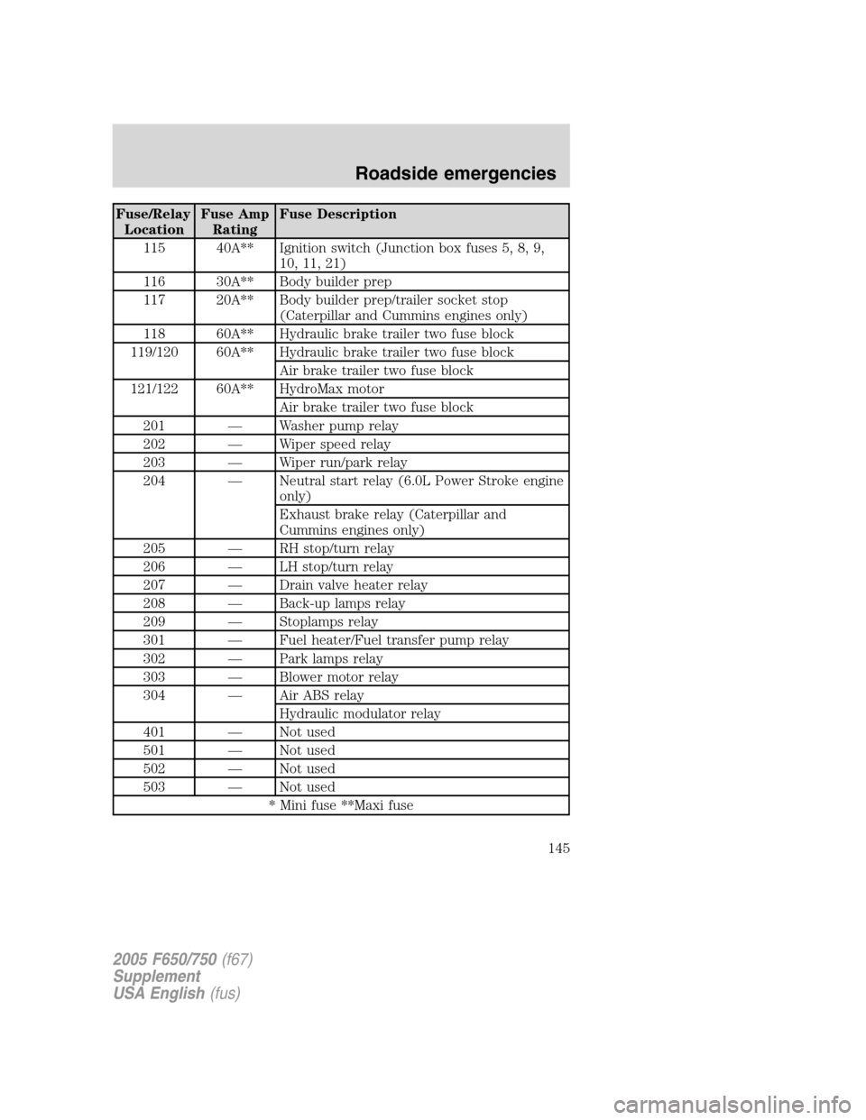
Fuse/Relay
LocationFuse Amp
RatingFuse Description
115 40A** Ignition switch (Junction box fuses 5, 8, 9,
10, 11, 21)
116 30A** Body builder prep
117 20A** Body builder prep/trailer socket stop
(Caterpillar and Cummins engines only)
118 60A** Hydraulic brake trailer two fuse block
119/120 60A** Hydraulic brake trailer two fuse block
Air brake trailer two fuse block
121/122 60A** HydroMax motor
Air brake trailer two fuse block
201—Washer pump relay
202—Wiper speed relay
203—Wiper run/park relay
204—Neutral start relay (6.0L Power Stroke engine
only)
Exhaust brake relay (Caterpillar and
Cummins engines only)
205—RH stop/turn relay
206—LH stop/turn relay
207—Drain valve heater relay
208—Back-up lamps relay
209—Stoplamps relay
301—Fuel heater/Fuel transfer pump relay
302—Park lamps relay
303—Blower motor relay
304—Air ABS relay
Hydraulic modulator relay
401—Not used
501—Not used
502—Not used
503—Not used
* Mini fuse **Maxi fuse
2005 F650/750(f67)
Supplement
USA English(fus)
Roadside emergencies
145
Page 146 of 272
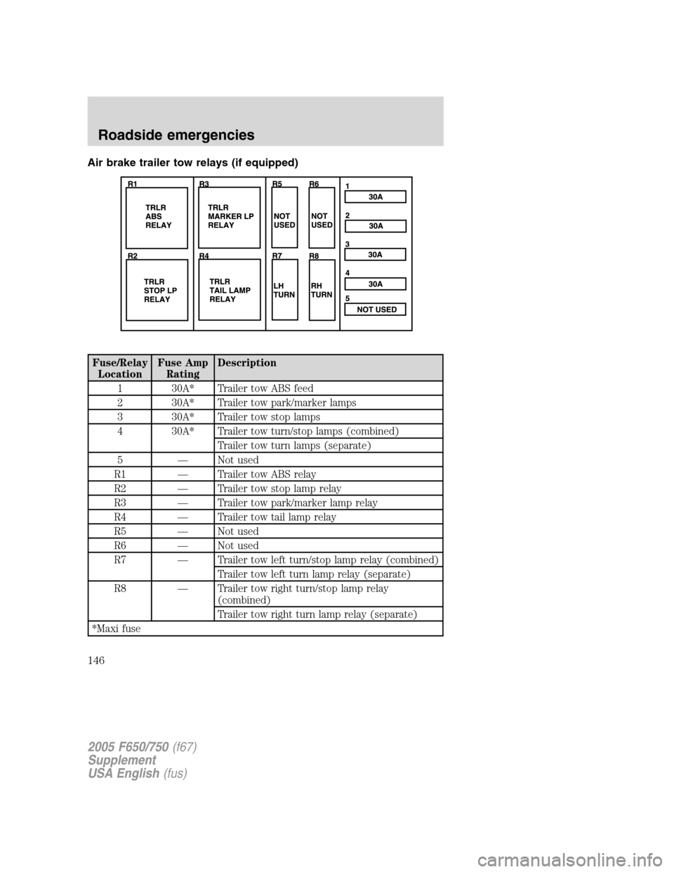
Air brake trailer tow relays (if equipped)
Fuse/Relay
LocationFuse Amp
RatingDescription
1 30A* Trailer tow ABS feed
2 30A* Trailer tow park/marker lamps
3 30A* Trailer tow stop lamps
4 30A* Trailer tow turn/stop lamps (combined)
Trailer tow turn lamps (separate)
5—Not used
R1—Trailer tow ABS relay
R2—Trailer tow stop lamp relay
R3—Trailer tow park/marker lamp relay
R4—Trailer tow tail lamp relay
R5—Not used
R6—Not used
R7—Trailer tow left turn/stop lamp relay (combined)
Trailer tow left turn lamp relay (separate)
R8—Trailer tow right turn/stop lamp relay
(combined)
Trailer tow right turn lamp relay (separate)
*Maxi fuse
2005 F650/750(f67)
Supplement
USA English(fus)
Roadside emergencies
146
Page 147 of 272
JUMP STARTING YOUR VEHICLE
The gases around the battery can explode if exposed to flames,
sparks, or lit cigarettes. An explosion could result in injury or
vehicle damage.
Batteries contain sulfuric acid which can burn skin, eyes and
clothing, if contacted.
Do not attempt to push-start your vehicle. Automatic
transmissions do not have push-start capability; doing so may
damage the catalytic converter.
Before connecting a fast-charger, booster battery or installing a new
battery, make sure the ground polarities of the fast-charger, booster
battery or alternator (when installing a battery) are matched to the
ground polarity of the vehicle battery. Improper usage of the
fast-charger, hook-up of booster battery or installation of a new battery
can cause damage to the electrical system or to the alternator. Do not
attempt to polarize the alternator.
Jump starting your vehicle
The gases around the battery can explode if exposed to flames,
sparks, or lit cigarettes. An explosion could result in injury or
vehicle damage.
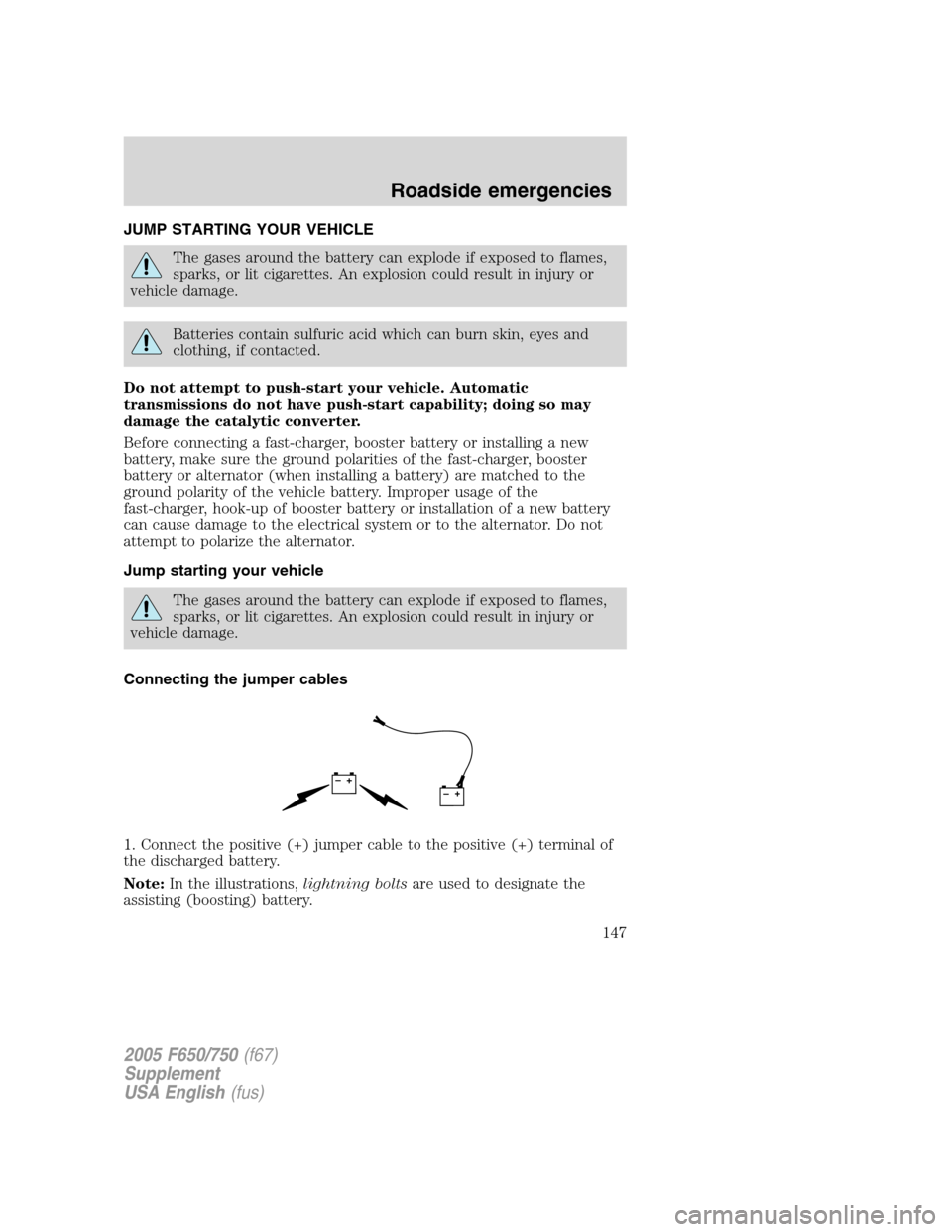
Connecting the jumper cables
1. Connect the positive (+) jumper cable to the positive (+) terminal of
the discharged battery.
Note:In the illustrations,lightning boltsare used to designate the
assisting (boosting) battery.
+–+–
2005 F650/750(f67)
Supplement
USA English(fus)
Roadside emergencies
147
Page 148 of 272
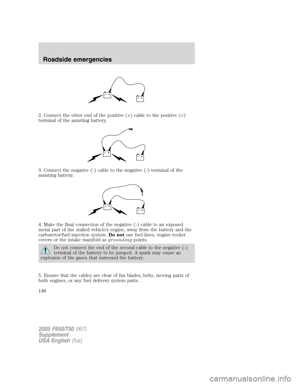
2. Connect the other end of the positive (+) cable to the positive (+)
terminal of the assisting battery.
3. Connect the negative (-) cable to the negative (-) terminal of the
assisting battery.
4. Make the final connection of the negative (-) cable to an exposed
metal part of the stalled vehicle’s engine, away from the battery and the
carburetor/fuel injection system.Do notuse fuel lines, engine rocker
covers or the intake manifold asgroundingpoints.
Do not connect the end of the second cable to the negative (-)
terminal of the battery to be jumped. A spark may cause an
explosion of the gases that surround the battery.
5. Ensure that the cables are clear of fan blades, belts, moving parts of
both engines, or any fuel delivery system parts.
+–+–
+–+–
+–+–
2005 F650/750(f67)
Supplement
USA English(fus)
Roadside emergencies
148
Page 149 of 272
Jump starting
1. Start the engine of the booster vehicle and run the engine at
moderately increased speed.
2. Start the engine of the disabled vehicle.
3. Once the disabled vehicle has been started, run both engines for an
additional three minutes before disconnecting the jumper cables.
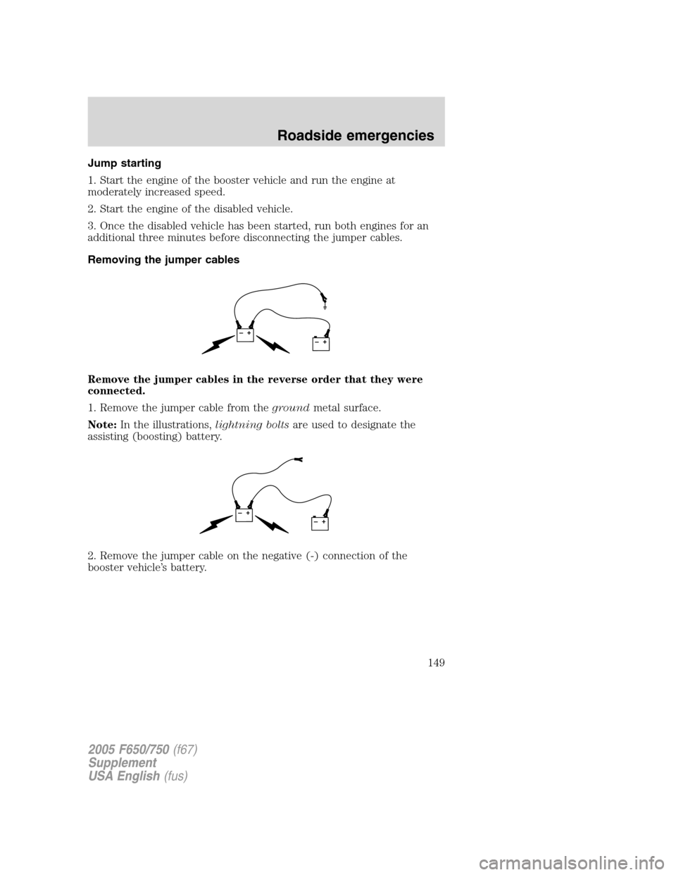
Removing the jumper cables
Remove the jumper cables in the reverse order that they were
connected.
1. Remove the jumper cable from thegroundmetal surface.
Note:In the illustrations,lightning boltsare used to designate the
assisting (boosting) battery.
2. Remove the jumper cable on the negative (-) connection of the
booster vehicle’s battery.
+–+–
+–+–
2005 F650/750(f67)
Supplement
USA English(fus)
Roadside emergencies
149
Page 150 of 272
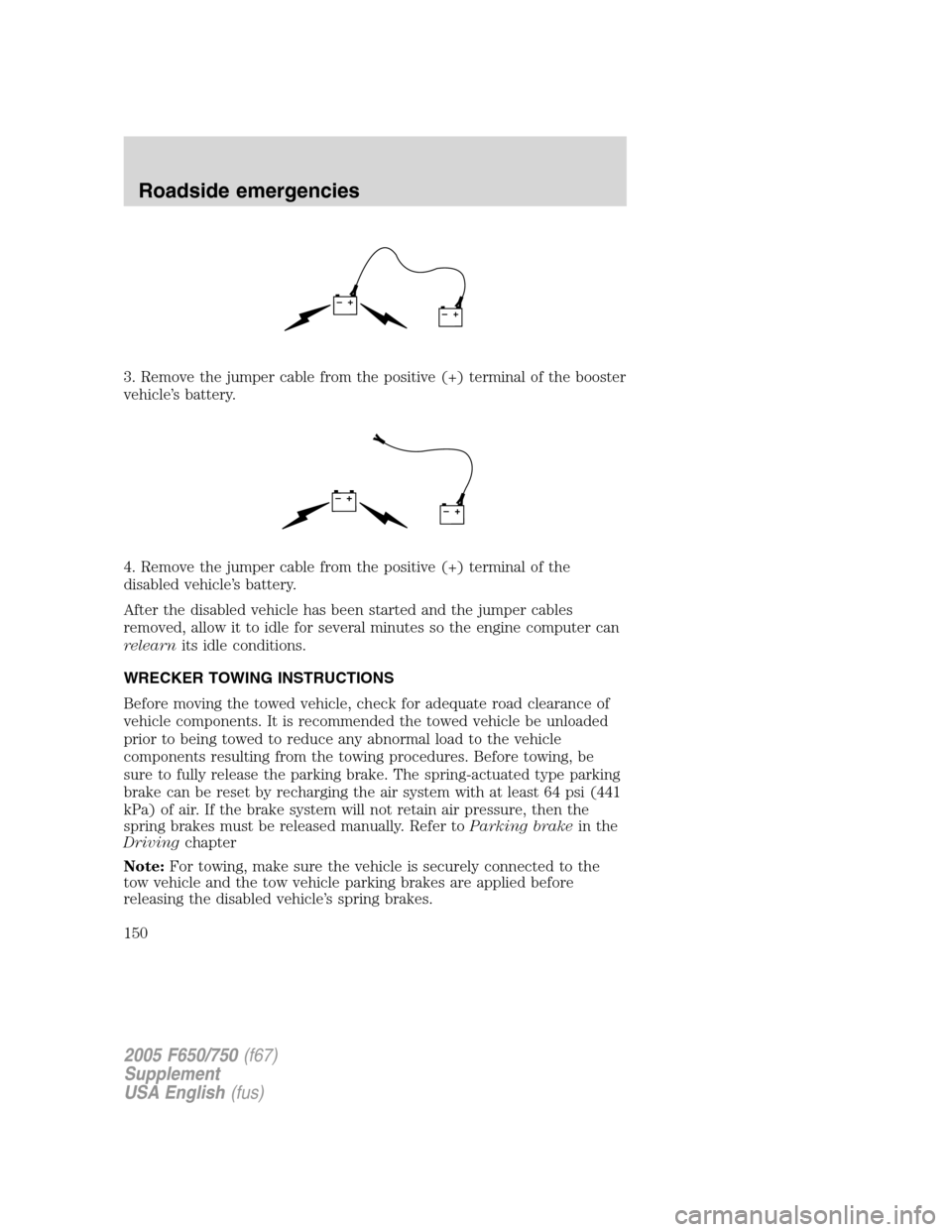
3. Remove the jumper cable from the positive (+) terminal of the booster
vehicle’s battery.
4. Remove the jumper cable from the positive (+) terminal of the
disabled vehicle’s battery.
After the disabled vehicle has been started and the jumper cables
removed, allow it to idle for several minutes so the engine computer can
relearnits idle conditions.
WRECKER TOWING INSTRUCTIONS
Before moving the towed vehicle, check for adequate road clearance of
vehicle components. It is recommended the towed vehicle be unloaded
prior to being towed to reduce any abnormal load to the vehicle
components resulting from the towing procedures. Before towing, be
sure to fully release the parking brake. The spring-actuated type parking
brake can be reset by recharging the air system with at least 64 psi (441
kPa) of air. If the brake system will not retain air pressure, then the
spring brakes must be released manually. Refer toParking brakein the
Drivingchapter
Note:For towing, make sure the vehicle is securely connected to the
tow vehicle and the tow vehicle parking brakes are applied before
releasing the disabled vehicle’s spring brakes.
+–+–
+–+–
2005 F650/750(f67)
Supplement
USA English(fus)
Roadside emergencies
150