alternator FORD F650 2005 11.G Owners Manual
[x] Cancel search | Manufacturer: FORD, Model Year: 2005, Model line: F650, Model: FORD F650 2005 11.GPages: 272, PDF Size: 1.5 MB
Page 11 of 272

To be sure your vehicle is ready to operate, conduct a pre-trip inspection
at the beginning of each work period. Follow the steps listed in this
section to assure a proper vehicle inspection procedure. The pages in
this section may be produced locally and used on a regular basis.
VEHICLE INSPECTION INFORMATION
Note:Always make sure the parking brake is applied before starting the
engine.
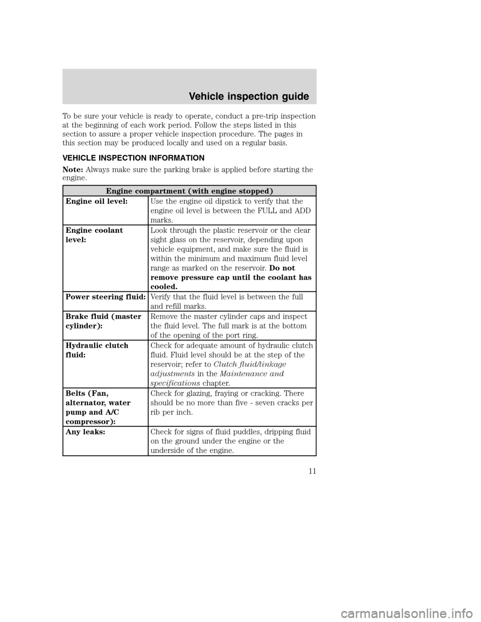
Engine compartment (with engine stopped)
Engine oil level:Use the engine oil dipstick to verify that the
engine oil level is between the FULL and ADD
marks.
Engine coolant
level:Look through the plastic reservoir or the clear
sight glass on the reservoir, depending upon
vehicle equipment, and make sure the fluid is
within the minimum and maximum fluid level
range as marked on the reservoir.Do not
remove pressure cap until the coolant has
cooled.
Power steering fluid:Verify that the fluid level is between the full
and refill marks.
Brake fluid (master
cylinder):Remove the master cylinder caps and inspect
the fluid level. The full mark is at the bottom
of the opening of the port ring.
Hydraulic clutch
fluid:Check for adequate amount of hydraulic clutch
fluid. Fluid level should be at the step of the
reservoir; refer toClutch fluid/linkage
adjustmentsin theMaintenance and
specificationschapter.
Belts (Fan,
alternator, water
pump and A/C
compressor):Check for glazing, fraying or cracking. There
should be no more than five - seven cracks per
rib per inch.
Any leaks:Check for signs of fluid puddles, dripping fluid
on the ground under the engine or the
underside of the engine.
Vehicle inspection guide
Vehicle inspection guide
11
Page 13 of 272

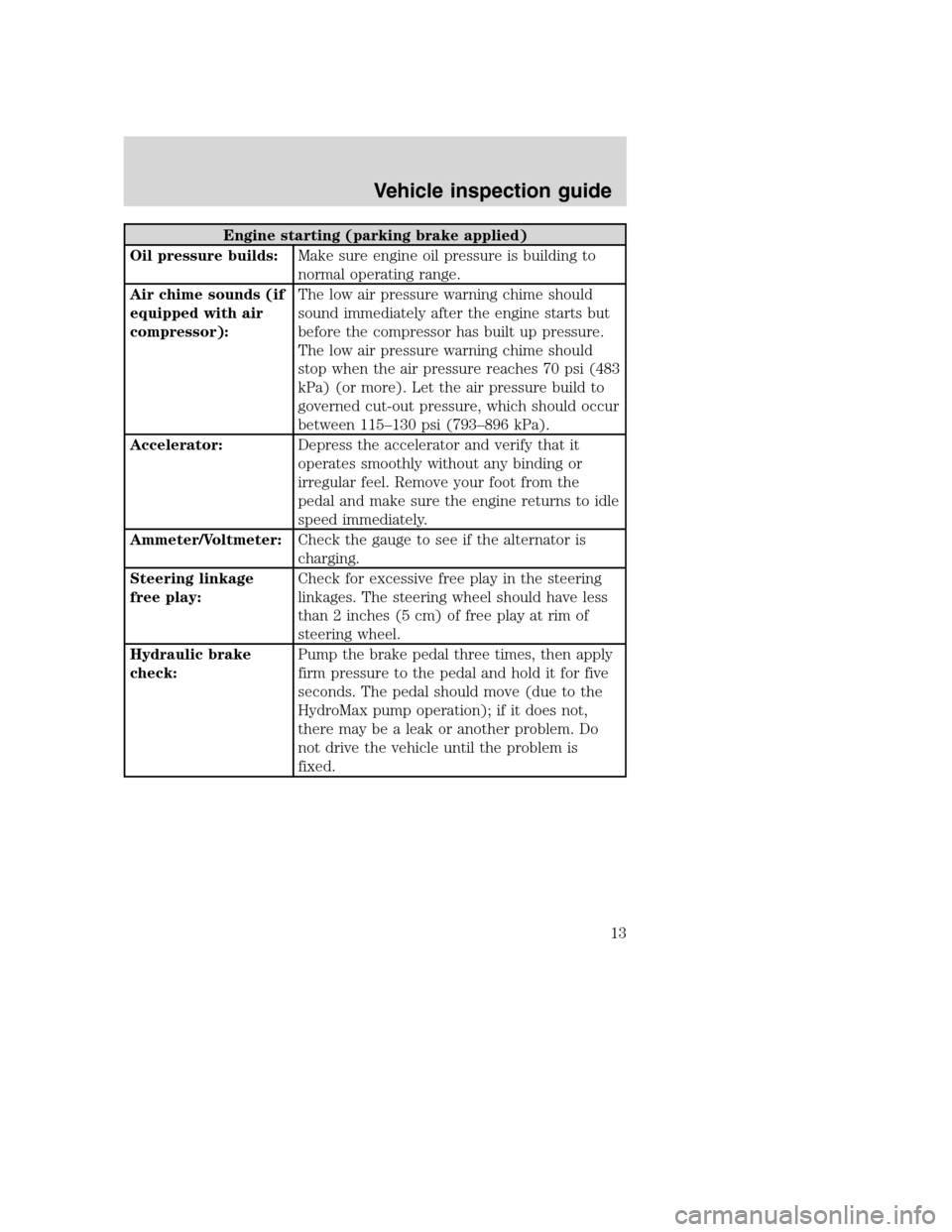
Engine starting (parking brake applied)
Oil pressure builds:Make sure engine oil pressure is building to
normal operating range.
Air chime sounds (if
equipped with air
compressor):The low air pressure warning chime should
sound immediately after the engine starts but
before the compressor has built up pressure.
The low air pressure warning chime should
stop when the air pressure reaches 70 psi (483
kPa) (or more). Let the air pressure build to
governed cut-out pressure, which should occur
between 115–130 psi (793–896 kPa).
Accelerator:Depress the accelerator and verify that it
operates smoothly without any binding or
irregular feel. Remove your foot from the
pedal and make sure the engine returns to idle
speed immediately.
Ammeter/Voltmeter:Check the gauge to see if the alternator is
charging.
Steering linkage
free play:Check for excessive free play in the steering
linkages. The steering wheel should have less
than 2 inches (5 cm) of free play at rim of
steering wheel.
Hydraulic brake
check:Pump the brake pedal three times, then apply
firm pressure to the pedal and hold it for five
seconds. The pedal should move (due to the
HydroMax pump operation); if it does not,
there may be a leak or another problem. Do
not drive the vehicle until the problem is
fixed.
Vehicle inspection guide
13
Page 147 of 272

JUMP STARTING YOUR VEHICLE
The gases around the battery can explode if exposed to flames,
sparks, or lit cigarettes. An explosion could result in injury or
vehicle damage.
Batteries contain sulfuric acid which can burn skin, eyes and
clothing, if contacted.
Do not attempt to push-start your vehicle. Automatic
transmissions do not have push-start capability; doing so may
damage the catalytic converter.
Before connecting a fast-charger, booster battery or installing a new
battery, make sure the ground polarities of the fast-charger, booster
battery or alternator (when installing a battery) are matched to the
ground polarity of the vehicle battery. Improper usage of the
fast-charger, hook-up of booster battery or installation of a new battery
can cause damage to the electrical system or to the alternator. Do not
attempt to polarize the alternator.
Jump starting your vehicle
The gases around the battery can explode if exposed to flames,
sparks, or lit cigarettes. An explosion could result in injury or
vehicle damage.
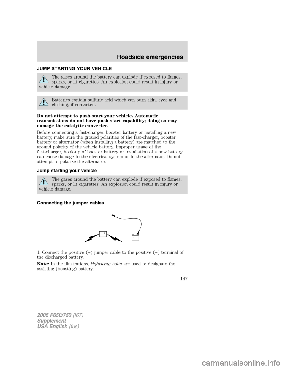
Connecting the jumper cables
1. Connect the positive (+) jumper cable to the positive (+) terminal of
the discharged battery.
Note:In the illustrations,lightning boltsare used to designate the
assisting (boosting) battery.
+–+–
2005 F650/750(f67)
Supplement
USA English(fus)
Roadside emergencies
147
Page 201 of 272

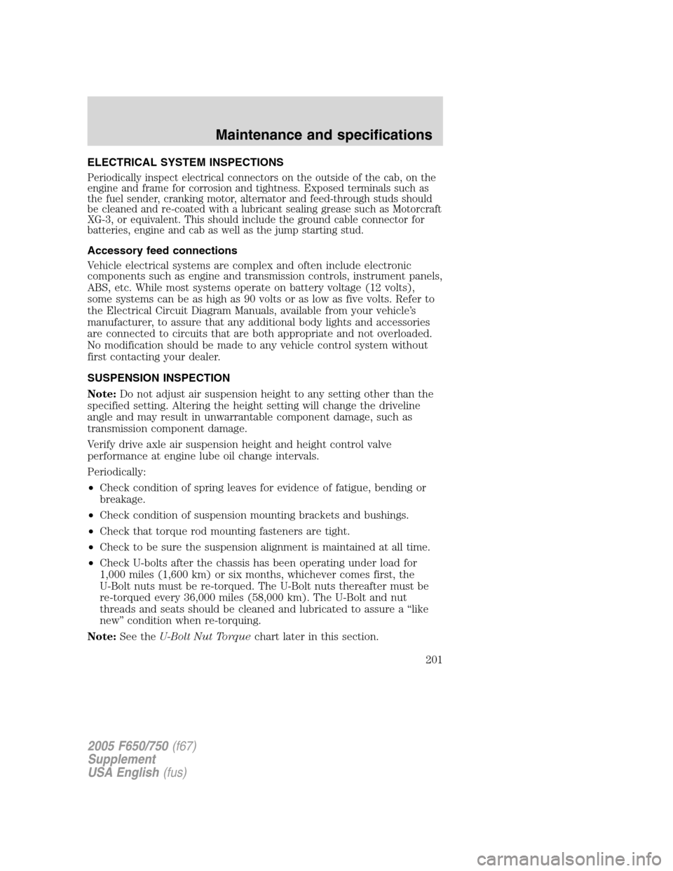
ELECTRICAL SYSTEM INSPECTIONS
Periodically inspect electrical connectors on the outside of the cab, on the
engine and frame for corrosion and tightness. Exposed terminals such as
the fuel sender, cranking motor, alternator and feed-through studs should
be cleaned and re-coated with a lubricant sealing grease such as Motorcraft
XG-3, or equivalent. This should include the ground cable connector for
batteries, engine and cab as well as the jump starting stud.
Accessory feed connections
Vehicle electrical systems are complex and often include electronic
components such as engine and transmission controls, instrument panels,
ABS, etc. While most systems operate on battery voltage (12 volts),
some systems can be as high as 90 volts or as low as five volts. Refer to
the Electrical Circuit Diagram Manuals, available from your vehicle’s
manufacturer, to assure that any additional body lights and accessories
are connected to circuits that are both appropriate and not overloaded.
No modification should be made to any vehicle control system without
first contacting your dealer.
SUSPENSION INSPECTION
Note:Do not adjust air suspension height to any setting other than the
specified setting. Altering the height setting will change the driveline
angle and may result in unwarrantable component damage, such as
transmission component damage.
Verify drive axle air suspension height and height control valve
performance at engine lube oil change intervals.
Periodically:
•Check condition of spring leaves for evidence of fatigue, bending or
breakage.
•Check condition of suspension mounting brackets and bushings.
•Check that torque rod mounting fasteners are tight.
•Check to be sure the suspension alignment is maintained at all time.
•Check U-bolts after the chassis has been operating under load for
1,000 miles (1,600 km) or six months, whichever comes first, the
U-Bolt nuts must be re-torqued. The U-Bolt nuts thereafter must be
re-torqued every 36,000 miles (58,000 km). The U-Bolt and nut
threads and seats should be cleaned and lubricated to assure a“like
new”condition when re-torquing.
Note:See theU-Bolt Nut Torquechart later in this section.
2005 F650/750(f67)
Supplement
USA English(fus)
Maintenance and specifications
201