wheel FORD F650 2005 11.G Owners Manual
[x] Cancel search | Manufacturer: FORD, Model Year: 2005, Model line: F650, Model: FORD F650 2005 11.GPages: 272, PDF Size: 1.5 MB
Page 1 of 272
Introduction 4
Congratulations 4
Safety and environment protection 5
Symbol glossary 8
Vehicle inspection guide 11
Instrumentation 21
Warning and control lights 21
Gauges 26
Entertainment systems 30
AM/FM stereo 30
AM/FM stereo cassette 32
AM/FM stereo cassette with CD 35
AM/FM stereo with CD 39
Climate controls 44
Heater only 44
Manual heating and air conditioning 45
Lights 47
Headlamps 47
Turn signal control 48
Interior lamps 49
Bulb replacement 49
Driver controls 52
Windshield wiper/washer control 52
Steering wheel adjustment 53
Power windows 55
Mirrors 56
Speed control 58
Table of Contents
1
2005 F650/750(f67)
Supplement
USA English(fus)
Table of Contents
Page 7 of 272
Event Data Recording
Other modules in your vehicle—event data recorders—are capable of
collecting and storing data during a crash or near crash event. The
recorded information may assist in the investigation of such an event.
The modules may record information about both the vehicle and the
occupants, potentially including information such as:
•how various systems in your vehicle were operating;
•whether or not the driver and passenger seatbelts were buckled;
•how far (if at all) the driver was depressing the accelerator and/or the
brake pedal;
•how fast the vehicle was traveling; and
•where the driver was positioning the steering wheel.
To access this information, special equipment must be directly connected
to the recording modules. Ford Motor Company and Ford of Canada do
not access event data recorder information without obtaining consent,
unless pursuant to court order or where required by law enforcement,
other government authorities or other third parties acting with lawful
authority. Other parties may seek to access the information
independently of Ford Motor Company and Ford of Canada.
Introduction
7
Page 12 of 272
Engine compartment (with engine stopped)
HVAC air inlet:Check for debris, leaves, etc. that may have
collected on the HVAC air inlet grille or inside
the exterior module as this may cause reduced
system performance.
HVAC fresh air filter
(if equipped):Periodically check the HVAC fresh air filter for
cleanliness.
Exercise great caution when working on vehicle equipped with
an automatic fan clutch. The fan starts in motion only after the
engine coolant reaches a predetermined temperature or the refrigerant
pressure (if equipped with air conditioning) reaches a predetermined
setting. The fan will start at these point with no advance warning.
Never reach near, or permit objects to protrude into, the fan blade
radius while the engine is running as this could result in vehicle
damage, personal injury or death.
Engine starting (parking brake applied)
Safety/Emergency
equipment:Prior to entering the cab, verify that the
vehicle is equipped with spare electrical fuses
(if used), three red reflective triangles, a
properly charged and rated fire extinguisher
and wheel chocks. Walk around the vehicle
and check that all steps and grab handles,
inside and out as well as behind, are tight and
clean. Use extreme caution and a three-point
stance at all times. Check door latches for
positive closing, latching and locking.
Starting the engine:Verify the parking brake is set. Depress the
clutch (if equipped with a manual
transmission) and verify the transmission is in
neutral. Vehicles equipped with an automatic
transmission should be in N (Neutral).
When the WAIT TO START indicator light in
the instrument cluster turns off, turn the key
to START.
Vehicle inspection guide
12
Page 13 of 272
Engine starting (parking brake applied)
Oil pressure builds:Make sure engine oil pressure is building to
normal operating range.
Air chime sounds (if
equipped with air
compressor):The low air pressure warning chime should
sound immediately after the engine starts but
before the compressor has built up pressure.
The low air pressure warning chime should
stop when the air pressure reaches 70 psi (483
kPa) (or more). Let the air pressure build to
governed cut-out pressure, which should occur
between 115–130 psi (793–896 kPa).
Accelerator:Depress the accelerator and verify that it
operates smoothly without any binding or
irregular feel. Remove your foot from the
pedal and make sure the engine returns to idle
speed immediately.
Ammeter/Voltmeter:Check the gauge to see if the alternator is
charging.
Steering linkage
free play:Check for excessive free play in the steering
linkages. The steering wheel should have less
than 2 inches (5 cm) of free play at rim of
steering wheel.
Hydraulic brake
check:Pump the brake pedal three times, then apply
firm pressure to the pedal and hold it for five
seconds. The pedal should move (due to the
HydroMax pump operation); if it does not,
there may be a leak or another problem. Do
not drive the vehicle until the problem is
fixed.
Vehicle inspection guide
13
Page 14 of 272
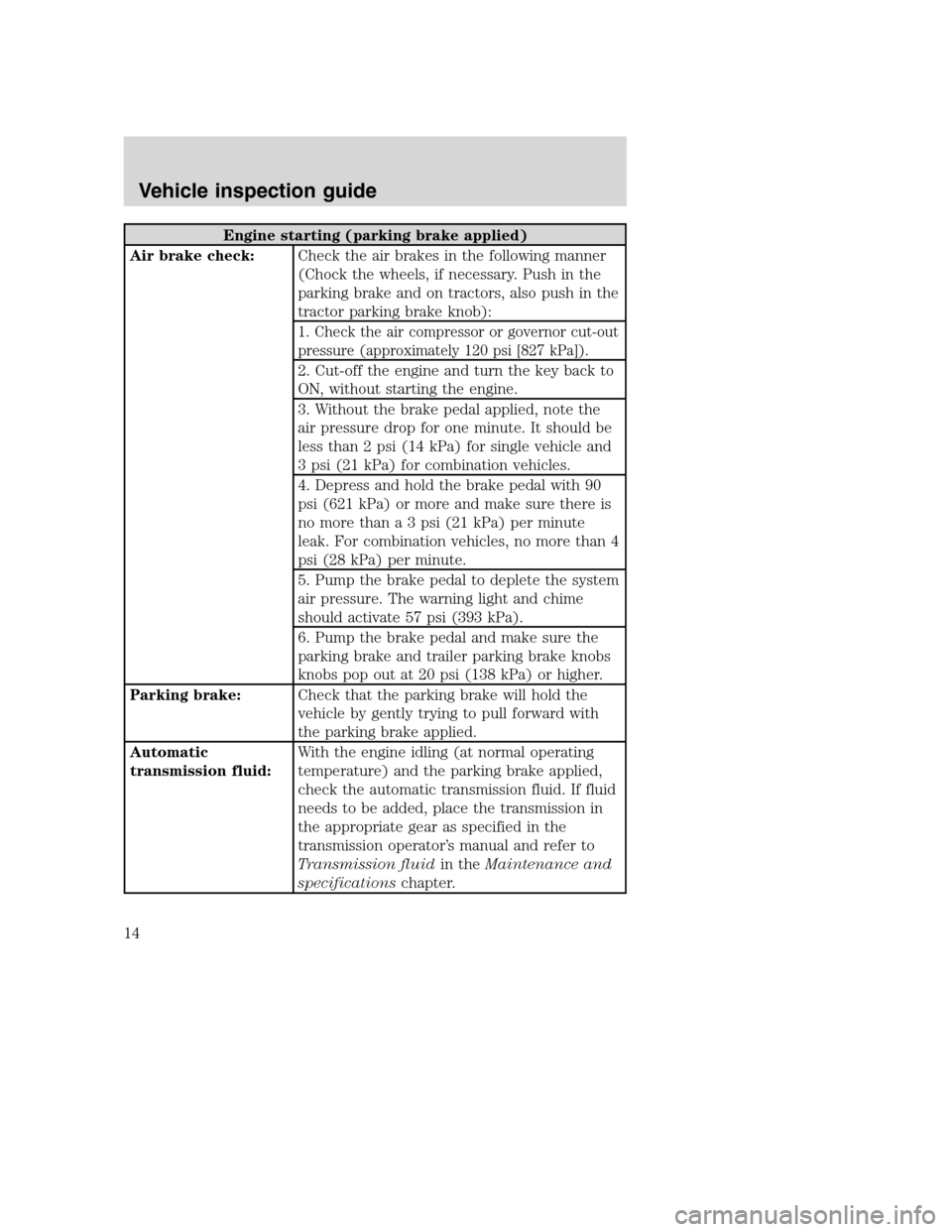
Engine starting (parking brake applied)
Air brake check:Check the air brakes in the following manner
(Chock the wheels, if necessary. Push in the
parking brake and on tractors, also push in the
tractor parking brake knob):
1. Check the air compressor or governor cut-out
pressure (approximately 120 psi [827 kPa]).
2. Cut-off the engine and turn the key back to
ON, without starting the engine.
3. Without the brake pedal applied, note the
air pressure drop for one minute. It should be
less than 2 psi (14 kPa) for single vehicle and
3 psi (21 kPa) for combination vehicles.
4. Depress and hold the brake pedal with 90
psi (621 kPa) or more and make sure there is
no more than a 3 psi (21 kPa) per minute
leak. For combination vehicles, no more than 4
psi (28 kPa) per minute.
5. Pump the brake pedal to deplete the system
air pressure. The warning light and chime
should activate 57 psi (393 kPa).
6. Pump the brake pedal and make sure the
parking brake and trailer parking brake knobs
knobs pop out at 20 psi (138 kPa) or higher.
Parking brake:Check that the parking brake will hold the
vehicle by gently trying to pull forward with
the parking brake applied.
Automatic
transmission fluid:With the engine idling (at normal operating
temperature) and the parking brake applied,
check the automatic transmission fluid. If fluid
needs to be added, place the transmission in
the appropriate gear as specified in the
transmission operator’s manual and refer to
Transmission fluidin theMaintenance and
specificationschapter.
Vehicle inspection guide
14
Page 16 of 272
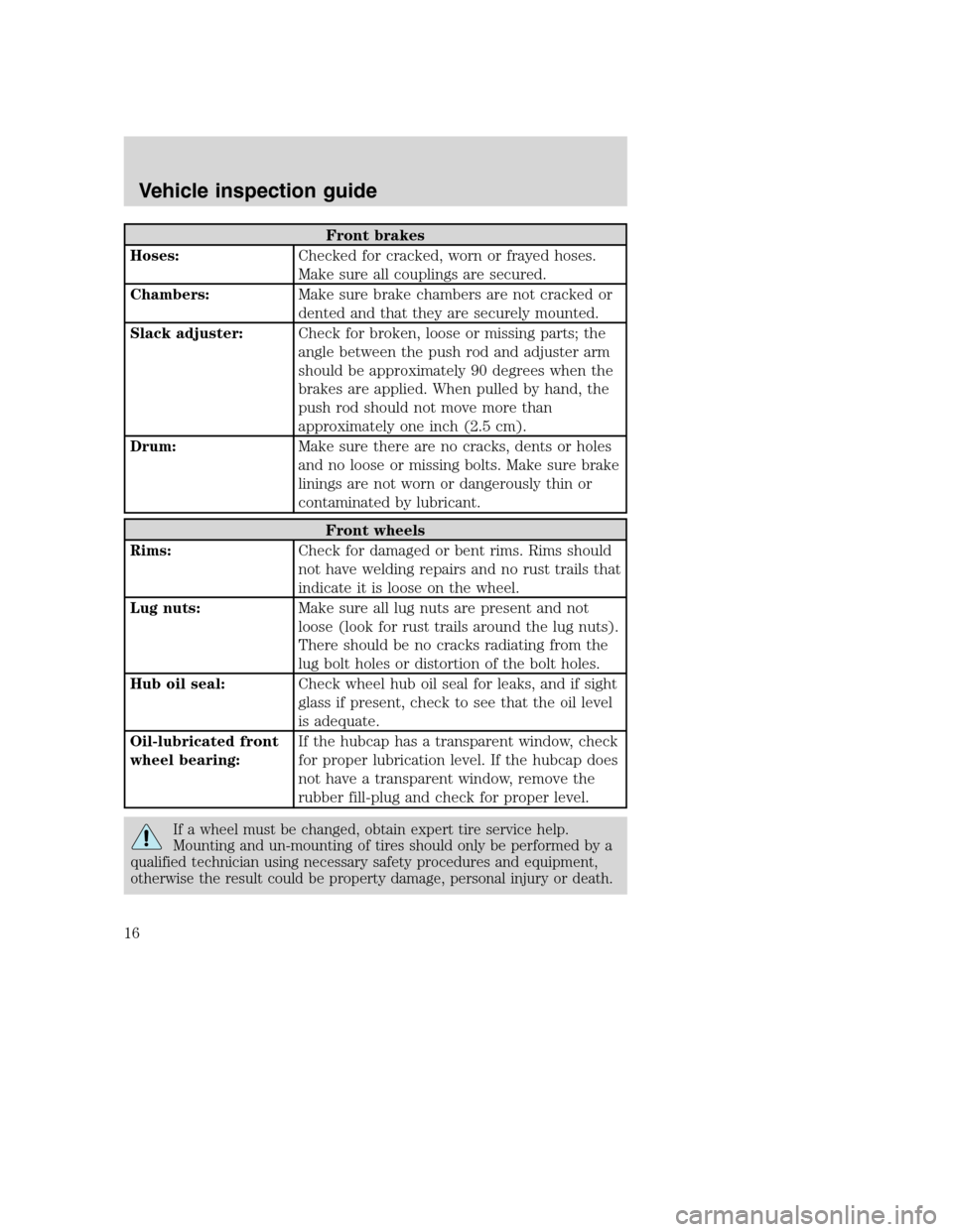
Front brakes
Hoses:Checked for cracked, worn or frayed hoses.
Make sure all couplings are secured.
Chambers:Make sure brake chambers are not cracked or
dented and that they are securely mounted.
Slack adjuster:Check for broken, loose or missing parts; the
angle between the push rod and adjuster arm
should be approximately 90 degrees when the
brakes are applied. When pulled by hand, the
push rod should not move more than
approximately one inch (2.5 cm).
Drum:Make sure there are no cracks, dents or holes
and no loose or missing bolts. Make sure brake
linings are not worn or dangerously thin or
contaminated by lubricant.
Front wheels
Rims:Check for damaged or bent rims. Rims should
not have welding repairs and no rust trails that
indicate it is loose on the wheel.
Lug nuts:Make sure all lug nuts are present and not
loose (look for rust trails around the lug nuts).
There should be no cracks radiating from the
lug bolt holes or distortion of the bolt holes.
Hub oil seal:Check wheel hub oil seal for leaks, and if sight
glass if present, check to see that the oil level
is adequate.
Oil-lubricated front
wheel bearing:If the hubcap has a transparent window, check
for proper lubrication level. If the hubcap does
not have a transparent window, remove the
rubber fill-plug and check for proper level.
If a wheel must be changed, obtain expert tire service help.
Mounting and un-mounting of tires should only be performed by a
qualified technician using necessary safety procedures and equipment,
otherwise the result could be property damage, personal injury or death.
Vehicle inspection guide
16
Page 18 of 272
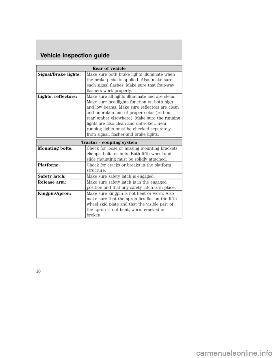
Rear of vehicle
Signal/Brake lights:Make sure both brake lights illuminate when
the brake pedal is applied. Also, make sure
each signal flashes. Make sure that four-way
flashers work properly.
Lights, reflectors:Make sure all lights illuminate and are clean.
Make sure headlights function on both high
and low beams. Make sure reflectors are clean
and unbroken and of proper color (red on
rear, amber elsewhere). Make sure the running
lights are also clean and unbroken. Rear
running lights must be checked separately
from signal, flasher and brake lights.
Tractor - coupling system
Mounting bolts:Check for loose or missing mounting brackets,
clamps, bolts or nuts. Both fifth wheel and
slide mounting must be solidly attached.
Platform:Check for cracks or breaks in the platform
structure.
Safety latch:Make sure safety latch is engaged.
Release arm:Make sure safety latch is in the engaged
position and that any safety latch is in place.
Kingpin/Apron:Make sure kingpin is not bent or worn. Also
make sure that the apron lies flat on the fifth
wheel skid plate and that the visible part of
the apron is not bent, worn, cracked or
broken.
Vehicle inspection guide
18
Page 20 of 272
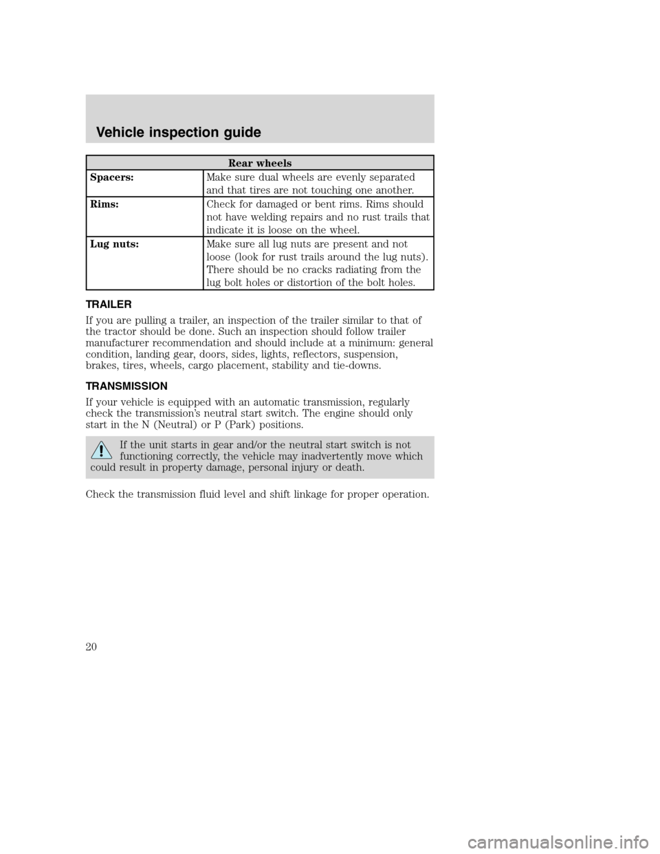
Rear wheels
Spacers:Make sure dual wheels are evenly separated
and that tires are not touching one another.
Rims:Check for damaged or bent rims. Rims should
not have welding repairs and no rust trails that
indicate it is loose on the wheel.
Lug nuts:Make sure all lug nuts are present and not
loose (look for rust trails around the lug nuts).
There should be no cracks radiating from the
lug bolt holes or distortion of the bolt holes.
TRAILER
If you are pulling a trailer, an inspection of the trailer similar to that of
the tractor should be done. Such an inspection should follow trailer
manufacturer recommendation and should include at a minimum: general
condition, landing gear, doors, sides, lights, reflectors, suspension,
brakes, tires, wheels, cargo placement, stability and tie-downs.
TRANSMISSION
If your vehicle is equipped with an automatic transmission, regularly
check the transmission’s neutral start switch. The engine should only
start in the N (Neutral) or P (Park) positions.
If the unit starts in gear and/or the neutral start switch is not
functioning correctly, the vehicle may inadvertently move which
could result in property damage, personal injury or death.
Check the transmission fluid level and shift linkage for proper operation.
Vehicle inspection guide
20
Page 22 of 272
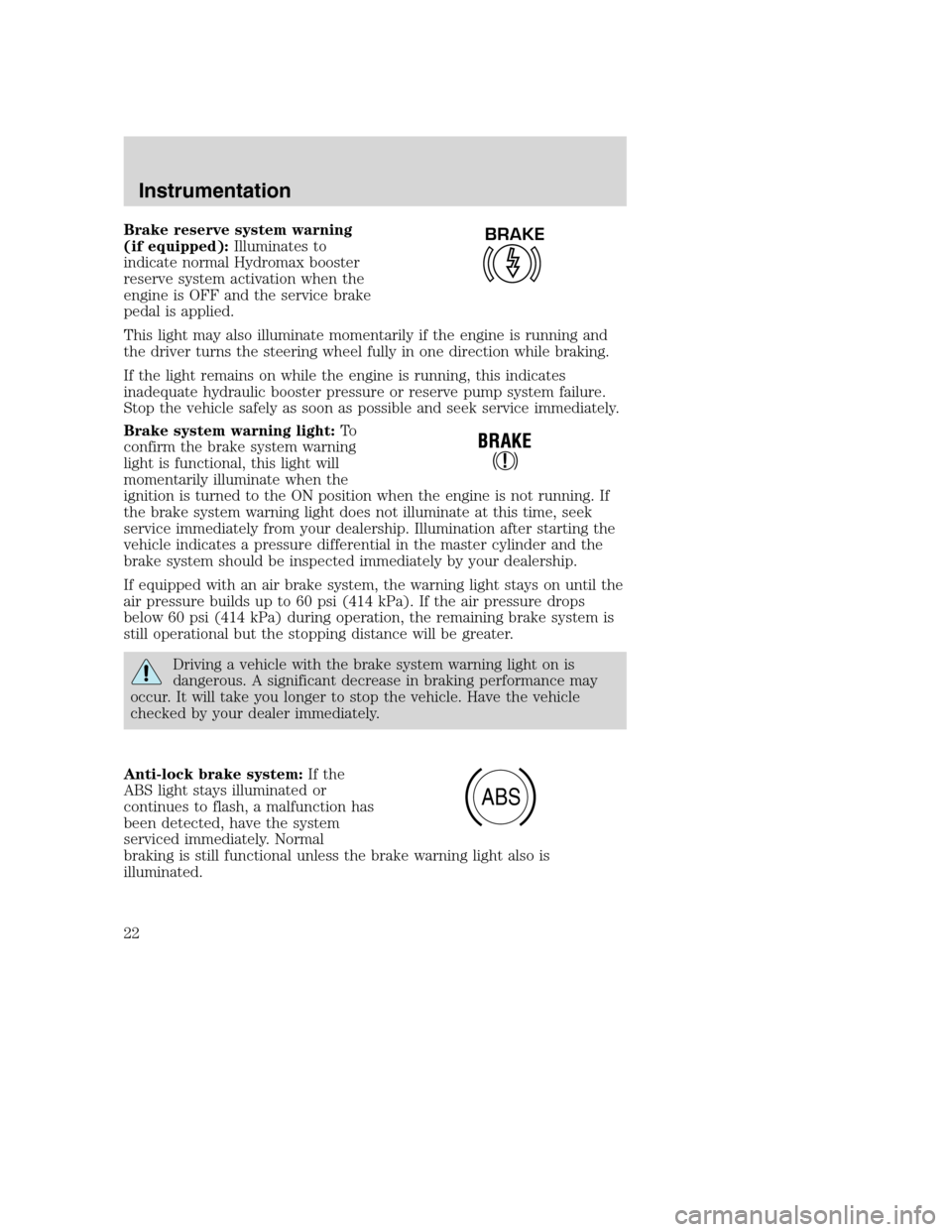
Brake reserve system warning
(if equipped):Illuminates to
indicate normal Hydromax booster
reserve system activation when the
engine is OFF and the service brake
pedal is applied.
This light may also illuminate momentarily if the engine is running and
the driver turns the steering wheel fully in one direction while braking.
If the light remains on while the engine is running, this indicates
inadequate hydraulic booster pressure or reserve pump system failure.
Stop the vehicle safely as soon as possible and seek service immediately.
Brake system warning light:To
confirm the brake system warning
light is functional, this light will
momentarily illuminate when the
ignition is turned to the ON position when the engine is not running. If
the brake system warning light does not illuminate at this time, seek
service immediately from your dealership. Illumination after starting the
vehicle indicates a pressure differential in the master cylinder and the
brake system should be inspected immediately by your dealership.
If equipped with an air brake system, the warning light stays on until the
air pressure builds up to 60 psi (414 kPa). If the air pressure drops
below 60 psi (414 kPa) during operation, the remaining brake system is
still operational but the stopping distance will be greater.
Driving a vehicle with the brake system warning light on is
dangerous. A significant decrease in braking performance may
occur. It will take you longer to stop the vehicle. Have the vehicle
checked by your dealer immediately.
Anti-lock brake system:If the
ABS light stays illuminated or
continues to flash, a malfunction has
been detected, have the system
serviced immediately. Normal
braking is still functional unless the brake warning light also is
illuminated.
BRAKE
ABS
Instrumentation
22
Page 53 of 272
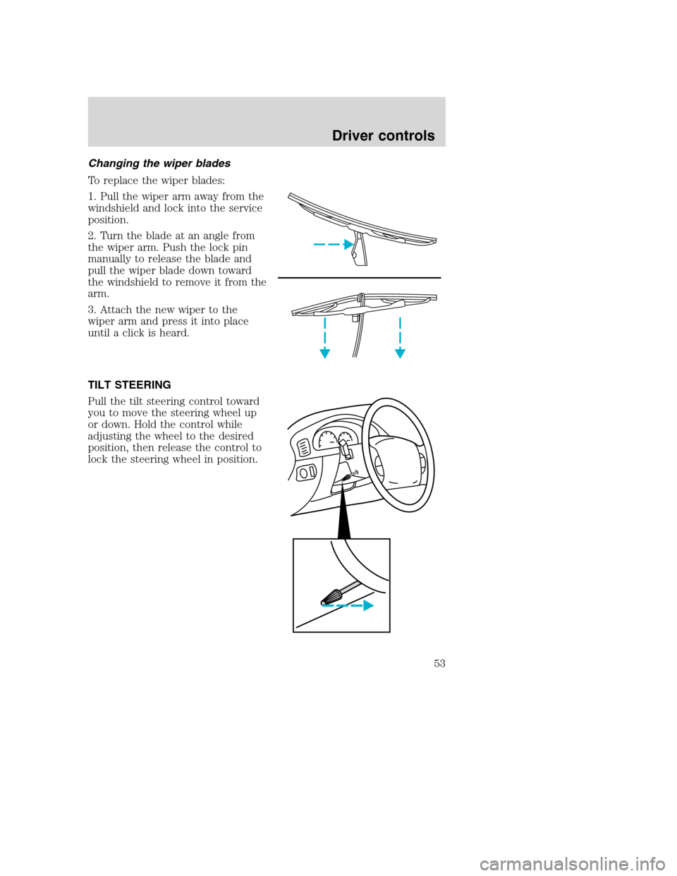
Changing the wiper blades
To replace the wiper blades:
1. Pull the wiper arm away from the
windshield and lock into the service
position.
2. Turn the blade at an angle from
the wiper arm. Push the lock pin
manually to release the blade and
pull the wiper blade down toward
the windshield to remove it from the
arm.
3. Attach the new wiper to the
wiper arm and press it into place
until a click is heard.
TILT STEERING
Pull the tilt steering control toward
you to move the steering wheel up
or down. Hold the control while
adjusting the wheel to the desired
position, then release the control to
lock the steering wheel in position.
Driver controls
53