air condition FORD F650 2006 11.G Owner's Manual
[x] Cancel search | Manufacturer: FORD, Model Year: 2006, Model line: F650, Model: FORD F650 2006 11.GPages: 272, PDF Size: 1.86 MB
Page 171 of 272

non-asbestos, fiberglass, mineral wool, aramid or carbon) may be a
potentially serious health hazard.
Avoid breathing brake lining fiber dust as it may be extremely
hazardous to your health. Always use a respirator during brake
maintenance.
Note:Persons handling brake linings should follow all precautions listed
below:
1. Always wear a respirator approved by the National Institute of
Occupational Studies of Health (NIOSH) or Mine Safety and Appliance
(MSA) during all brake service procedures. Wear the respirator from
removal of the wheels through assembly.
2.Neveruse compressed air or dry brushing to clean brake parts or
assemblies.
3. Clean brake parts and assemblies in open air. During assembly,
carefully place all parts on the floor to avoid getting dust in the air. Use
an industrial vacuum cleaner with a HEPA filter system to clean dust
from the brake drums, backing plates and other brake parts. After using
the vacuum, remove any remaining dust with a rag soaked in water and
wrung until nearly dry.
4.Neveruse compressed air or dry sweeping to clean the work area.
Use an industrial vacuum cleaner with a HEPA filter system and rags
soaked in water until wrung until nearly dry. Dispose of used rags with
care to avoid getting dust in the air. Use an approved respirator when
emptying vacuum cleaners and handling used rags.
5.Worker clean-up:Wash your hands before eating, drinking or
smoking. Vacuum your work clothes after use and then launder them
separately, without shaking them, to prevent fiber dust getting into the
air.
Air brakes - inspection and adjustment
A regular schedule for periodic cleaning, lubrication, adjustment and
inspection should be established based on the type of vehicle operation.
It is difficult to predetermine an exact maintenance interval (time or
mileage), since vehicles will be used in a wide variety of applications and
conditions. If you are uncertain of the proper schedule and procedures
for your vehicle, contact your dealer.
Periodic checking of push rod travel or brake adjustment is essential for
effective braking. Push rod travel should be checked every service
2006 F-650/750(f67)
Supplement
USA(fus)
Maintenance and Specifications
171
Page 172 of 272
interval to determine if adjustment is necessary. Brake chamber push
rods on original equipment chambers now incorporate a stroke indicator
to aid in adjustment checks; an orange paint marker near the base of the
push rod. If the push rod is clean and the brakes require adjustment, the
orange marker can be seen protruding from the chamber when the
brakes are applied.
Slack adjusters should also be checked to ensure proper operation of the
adjuster mechanism at the six-month interval. Push rod travel should be
kept at a minimum without the brakes dragging.
Inspect the brake lining every maintenance interval. When brake lining or
blocks are worn to within 1/16 inch (1.6 mm) of rivets, brake lining must
be replaced. This inspection or adjustment should only be performed by
a qualified technician and must be in accordance with instructions
provided by the service manual.
Do not back off or disconnect the front brakes so that they are less
effective, letting the rear brakes do all the stopping of the vehicle. Do
not overlook the brakes on the trailer, either. Brake condition on the
trailer is just as important as the tractor. Proper brake balance on trucks
and tractor-trailers is essential for effective braking.
Once a year, the entire brake system must be inspected. Check the
following:
•Any rubber as it may deteriorate whenever used. Rubber brake
components should be inspected by a qualified technician and
replaced as necessary. Replacement intervals vary according to the
severity and length of vehicle service.
•Condition of brake drums, brake chambers and slack adjusters.
•System for air leaks.
•Hose or pipes for rust, damage and deterioration.
•Operation of service and parking brakes.
Some parts such as air brake chamber diaphragm, air compressor and air
cleaner should be inspected periodically and replaced if considered
unserviceable.
Air brakes - air dryer
Performance of desiccant or after-cooler type air dryers is dependent on
climatic conditions in which your vehicle is operating. Maintenance
schedules must be established for each specific operation.
The use of an air dryer on a vehicle does not eliminate the need to
periodically drain the air reservoirs.
2006 F-650/750(f67)
Supplement
USA(fus)
Maintenance and Specifications
172
Page 173 of 272
Air brakes - desiccant air dryer
Inspect for moisture in the air system by opening reservoirs, drain cocks
or valves and checking for presence of water. The presence of small
amounts of water due to condensation is normal and should not be
considered as an indication that the dryer is not functioning properly.
The desiccant cartridge should be replaced or rebuilt when it has been
determined that the desiccant is contaminated and does not have
adequate water absorption capacity. The desiccant change interval may
vary; it is generally recommended that the desiccant be replaced every
12 months (yearly). If experience has shown that extended or shortened
life has resulted for a particular installation, then the yearly interval can
be increased or decreased accordingly.
Hydraulic brakes - general inspection and adjustment
A regular schedule for periodic cleaning, lubrication, adjustment and
inspection should be established based on the type of vehicle operation.
It is difficult to predetermine an exact maintenance interval (time or
mileage), since vehicles will be used in a wide variety of applications and
conditions. If you are uncertain of the proper schedule and procedures
for your vehicle, contact your dealer.
Inspect the brake lining every maintenance interval. Establish inspection
intervals that provide for lining replacement before damage to the disc
occurs. Excessive lining wear may expose the backing plate to the disc
causing scoring of the disc faces.
This inspection should be performed by a qualified technician and must
be in accordance with instructions provided by the service manual.
Note:Hydraulic brake system are power assisted. Braking capabilities
will be greatly reduced without engine assist.
Hydraulic brakes - fluid level
Fluid level should be at the bottom edge of the ring on each reservoir fill
port. Do not fill the master cylinder to the top of the reservoir.
Note:If brake fluid requires attention to maintain a proper master
cylinder level, this is an indication of either severe operation (pad wear)
or fluid system leakage. A more frequent and thorough brake inspection
will be required.
Hydraulic brakes - fluid precautions
The HydroMax brake system consists of two completely separate
hydraulic systems operating with two different and incompatible fluids;
2006 F-650/750(f67)
Supplement
USA(fus)
Maintenance and Specifications
173
Page 175 of 272
Note:If your vehicle is equipped with a vertical exhaust pipe, it is very
important to have and maintain a rain cap on the exhaust pipe to
prevent water from entering the exhaust system and catalytic converter.
Any water entering the catalytic converter may damage the catalyst and
affect the function of the converter.
Air induction system
Once each year, perform a complete inspection of the air induction
system. In areas where road salt is used, the inspection consists of
disassembling the joints of each aluminum component and inspecting for
salt build-up, presence of chlorine that can cause aluminum particles to
flake off and enter the engine combustion chambers.
If evidence of corrosion is found (usually at the pipe connections), use a
wire brush to clean the inside of the pipes and inside the rubber hoses.
If the intake pipes are pitted at the joint ends, use Motorcraft Silicone
Gasket and Sealant TA-30 to seal the joints. Be certain that no excess
material is on the inside of the pipes that can be pulled into the engine.
If the service condition of the pipes, hoses or clamps is questionable,
replace the defective part(s).
Be sure that prior to reassembly all dust and debris has been cleaned out
of the pipes and couplings with a clean, damp rag.
To reduce the risk of personal injury or death when performing
maintenance to any turbocharged engine with engine air inlet
piping disconnected, a turbocharger compressor air inlet protective
shield should be installed over the turbocharger air inlet.
Cummins B and Caterpillar engines
Refer to the respective engine operator manual for air filter replacement
procedure.
OPENING THE HOOD
The hood and fenders are held in position by a latch located on each
fender.
The parking brake must be fully set before opening the hood or
possible personal injury may occur.
To reduce the risk of the possibility of personal injury, never
stand beneath the hood when it is being raised or lowered.
2006 F-650/750(f67)
Supplement
USA(fus)
Maintenance and Specifications
175
Page 189 of 272
•Check tie rod, drag link end clamp bolts and ball joints. They must be
tight.
•Check for installation and spread of cotter pins and tightness of nuts
at both ends of the tie rod and drag link.
•Check that pitman arm (steering arm at steering gear) mounting is
tight and locked. Check system for leaks or hose chafing. Repair at
once.
•Maintain proper steering gear and power steering pump lubricant
levels.
•Regularly inspect steering column joint bolts and steering linkage,
particularly for body-to-chassis clearance.
Note:Have any steering problems corrected at once by a qualified
service technician.
Failure to maintain the steering system in proper condition can
cause reduced steering ability resulting in property damage,
personal injury or death.
Tightening steering column joint bolts
As a good maintenance practice, it is recommended that steering column
joint bolts be checked for tightness every 60,000 miles (96,000 km) or
annually, whichever occurs first. DO NOT OVERTIGHTEN.
Power steering
Whenever the power steering’s hydraulic system has been drained and
refilled for any reason, air must be bled from the system before returning
the vehicle to service. Failure to properly bleed the hydraulic system can
result in degradation of power system performance.
Consult your dealer who is aware of the proper procedures for filling and
bleeding the system.
Power steering fluid
Check the power steering fluid level using the following procedure. If
adding fluid is necessary, refer toLubricant Specificationsin this
chapter for the proper fluid type. Refer to theScheduled Maintenance
Guidechapter for the recommended service intervals.
1. Set the parking brake, shift into N (Neutral) (automatic transmission)
or 1 (First) (manual transmission) and turn the engine off.
2006 F-650/750(f67)
Supplement
USA(fus)
Maintenance and Specifications
189
Page 200 of 272
•If your vehicle is equipped with a Caterpillar engine,the fuel
system must be primed before attempting to restart the engine. Refer
to the engine operator’s manual for instructions on priming the engine.
•Use caution not to overheat and damage the starterby cranking
the engine for an excessive period of time. You may need to crank the
engine for a longer time than normal. If the engine fails to start in 30
seconds, turn the ignition to the OFF position and wait for two
minutes before cranking the engine again.
•Any remaining trapped air will self-purge from the fuel system once
the engine starts running.
•The engine may run rough and produce white smoke while air is in
the fuel system. This is normal and should stop after a short period of
time.
FUEL CONSUMPTION IMPROVEMENT MEASURES
There are two important factors you can control to improve fuel
economy: the mechanical condition of your vehicle and how you drive it.
A properly maintained vehicle will deliver better performance than a
neglected vehicle. Always follow your maintenance schedule to keep your
vehicle in top operating condition.
Also, your driving habits have a significant influence on use of fuel. By
following these suggestions, you can stretch your fuel use:
•Avoid changes in speed as much as possible.
•Anticipate changing traffic conditions. Sudden stops and fast
acceleration waste fuel.
•Avoid extensive idling.
•Do not drive with your foot resting on the brake pedal.
Essentials of good fuel economy
Measuring techniques
Your best source of information about actual fuel economy is you, the
driver. You must gather information as accurately and consistently as
possible. Fuel expense, frequency of fill-ups or fuel gauge readings are
NOT accurate as a measure of fuel economy. We do not recommend
taking fuel economy measurements during the first 1,000 miles (1,600
km) of driving (engine break-in period). You will get a more accurate
measurement after 2,000–3,000 miles (3,000–5,000 km).
The advertised fuel capacity of the fuel tank(s) on your vehicle is equal
to the rated refill capacity of the fuel tank(s) as listed inFuel tanksin
2006 F-650/750(f67)
Supplement
USA(fus)
Maintenance and Specifications
200
Page 202 of 272
•Multiply liters used by 100, then divide by total kilometers traveled.
Keep a record for at least one month and record the type of driving (city
or highway). This will provide an accurate estimate of the vehicle’s fuel
economy under current driving conditions. Additionally, keeping records
during summer and winter will show how temperature impacts fuel
economy. In general, lower temperatures give lower fuel economy.
Driving style - good driving and fuel economy habits
Give consideration to the lists that follow and you may be able to change
a number of variables and improve your fuel economy.
Habits
•Smooth, moderate operation can yield up to 10% savings in fuel.
•Steady speeds without stopping will usually give the best fuel
economy.
•Anticipate stopping; slowing down may eliminate the need to stop.
•Sudden or hard accelerations may reduce fuel economy.
•Slow down gradually.
•Driving at reasonable speeds (traveling at 55 mph [88 km/h] uses 15%
less fuel than traveling at 65 mph [105 km/h]).
•Using the air conditioner or defroster may reduce fuel economy.
•Resting your foot on the brake pedal while driving may reduce fuel
economy.
Conditions
•Carrying unnecessary weight may reduce fuel economy.
•Fuel economy may decrease with lower temperatures during the first
8–10 miles (12–16 km) of driving.
•Flat terrain driving improves fuel economy over hilly roads.
•Transmissions give their best fuel economy when operated in the top
cruise gear and with steady pressure on the accelerator.
•Close windows for highway driving.
NOISE EMISSIONS – EXTERIOR
In order to comply with the federal exterior noise regulations, your
vehicle may be equipped with noise emission items. Depending on the
vehicle configuration, it may have all or some of the following items:
2006 F-650/750(f67)
Supplement
USA(fus)
Maintenance and Specifications
202
Page 205 of 272
Verify drive axle air suspension height and height control valve
performance at engine lube oil change intervals.
Periodically:
•Check condition of spring leaves for evidence of fatigue, bending or
breakage.
•Check condition of suspension mounting brackets and bushings.
•Check that torque rod mounting fasteners are tight.
•Check to be sure the suspension alignment is maintained at all time.
•Check U-bolts after the chassis has been operating under load for
1,000 miles (1,600 km) or six months, whichever comes first, the
U-Bolt nuts must be re-torqued. The U-Bolt nuts thereafter must be
re-torqued every 36,000 miles (58,000 km). The U-Bolt and nut
threads and seats should be cleaned and lubricated to ensure a “like
new” condition when re-torquing.
Note:See theU-Bolt Nut Torquechart later in this section.
Supporting your vehicle for service
When performing service repairs on your vehicle, first prepare the
vehicle by doing the following:
1. Park the vehicle on a level concrete floor.
2. Set the parking brake and block the wheels to prevent the vehicle
from moving.
3. Select a jack with a rated capacity sufficient to lift and hold up the
vehicle.
4. Raise the vehicle with the jack applied to the axle(s). DO NOT use the
bumper as a lifting point.
5. Support the vehicle with floor stands under the axle(s). If the axle or
the suspension are being serviced, support the vehicle with floor stands
under the frame side-members, preferably between the axles.
Do not use a jack when working under a vehicle. It may give
way, causing the vehicle to fall and result in property damage,
personal injury or death. Always use floor stands to support the
vehicle.
2006 F-650/750(f67)
Supplement
USA(fus)
Maintenance and Specifications
205
Page 233 of 272
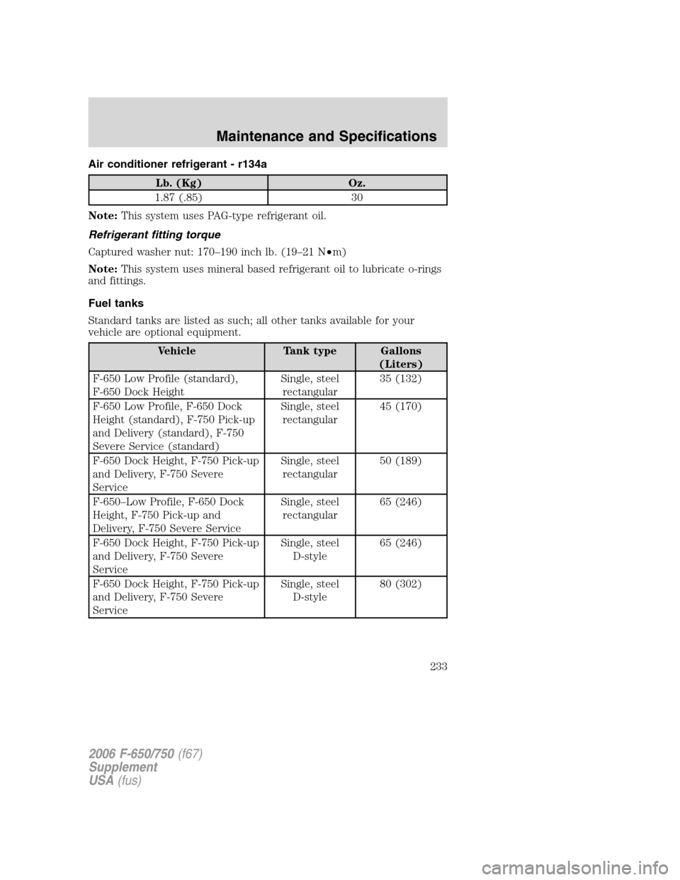
Air conditioner refrigerant - r134a
Lb. (Kg) Oz.
1.87 (.85) 30
Note:This system uses PAG-type refrigerant oil.
Refrigerant fitting torque
Captured washer nut: 170–190 inch lb. (19–21 N•m)
Note:This system uses mineral based refrigerant oil to lubricate o-rings
and fittings.
Fuel tanks
Standard tanks are listed as such; all other tanks available for your
vehicle are optional equipment.
Vehicle Tank type Gallons
(Liters)
F-650 Low Profile (standard),
F-650 Dock HeightSingle, steel
rectangular35 (132)
F-650 Low Profile, F-650 Dock
Height (standard), F-750 Pick-up
and Delivery (standard), F-750
Severe Service (standard)Single, steel
rectangular45 (170)
F-650 Dock Height, F-750 Pick-up
and Delivery, F-750 Severe
ServiceSingle, steel
rectangular50 (189)
F-650–Low Profile, F-650 Dock
Height, F-750 Pick-up and
Delivery, F-750 Severe ServiceSingle, steel
rectangular65 (246)
F-650 Dock Height, F-750 Pick-up
and Delivery, F-750 Severe
ServiceSingle, steel
D-style65 (246)
F-650 Dock Height, F-750 Pick-up
and Delivery, F-750 Severe
ServiceSingle, steel
D-style80 (302)
2006 F-650/750(f67)
Supplement
USA(fus)
Maintenance and Specifications
233
Page 235 of 272
GENERAL MAINTENANCE INFORMATION
The Scheduled Maintenance Services listed in this section are required
because they are considered essential to the life and performance of
your vehicle.
Ford Motor Company recommends you perform the Owner Maintenance
Services listed in this section. These services are matters of day-to-day
care that are important to the proper operation of your vehicle. In
addition to the conditions described in the Owner Maintenance Checklist,
be alert for any unusual noise, vibration or other indication that your
vehicle may need service and attend to it promptly.
Use only recommended fuels, lubricants, fluids and service parts
conforming to Ford specifications. Motorcraft parts are designed and
built for best performance in your vehicle. Using these parts for
replacement is your assurance that Ford-Built quality stays in your
vehicle.
SCHEDULED MAINTENANCE
The maintenance or replacement of the emission control devices (or
systems) in your new Ford Motor Company vehicle (or engine) may be
performed at your expense. These services may be performed by any
automotive repair establishment or individual using automotive parts
equivalent to those with which your vehicle or engine was originally
equipped. If any parts other than Ford, Motorcraft, or Ford authorized,
remanufactured parts are used for maintenance replacements (or for the
service) of components effecting the emission control, the owner should
be ensured that such parts are warranted by their manufacturer to be
equivalent to genuine Ford Motor Company Parts in performance and
durability. Please consult your warranty information booklet for complete
warranty information.
Authorized dealer maintenance
Your authorized dealer specializes in knowing all about Ford Motor
Company vehicles rather than knowing a little about all makes.
There are Ford or Ford of Canada dealer service shops ready to serve
you wherever you drive in the U.S. or Canada. They stock Ford and
Motorcraft parts, and Ford Chemicals and lubricants. You can be
confident that these meet the same exacting design and quality
standards as those used to build the vehicle originally. Dealer Service
Technicians have available training in the latest product developments
and service techniques.
2006 F-650/750(f67)
Supplement
USA(fus)
Scheduled Maintenance Guide
235