battery FORD F650 2006 11.G Owners Manual
[x] Cancel search | Manufacturer: FORD, Model Year: 2006, Model line: F650, Model: FORD F650 2006 11.GPages: 272, PDF Size: 1.86 MB
Page 3 of 272
Maintenance and Specifications 168
Hood 175
Engine oil 177
Battery 186
Fuel information 197
Lubricant specifications 218
Refill capacities 231
Scheduled Maintenance Guide 235
Motorcraft Premium Gold Coolant Change Record 265
Index 267
All rights reserved. Reproduction by any means, electronic or mechanical
including photocopying, recording or by any information storage and retrieval
system or translation in whole or part is not permitted without written
authorization from Ford Motor Company. Ford may change the contents without
notice and without incurring obligation.
Copyright © 2005 Ford Motor Company
Table of Contents
3
2006 F-650/750(f67)
Supplement
USA(fus)
Page 9 of 272
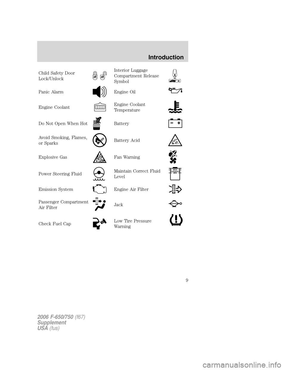
Child Safety Door
Lock/UnlockInterior Luggage
Compartment Release
Symbol
Panic AlarmEngine Oil
Engine CoolantEngine Coolant
Temperature
Do Not Open When HotBattery
Avoid Smoking, Flames,
or SparksBattery Acid
Explosive GasFan Warning
Power Steering FluidMaintain Correct Fluid
LevelMAX
MIN
Emission SystemEngine Air Filter
Passenger Compartment
Air FilterJack
Check Fuel CapLow Tire Pressure
Warning
2006 F-650/750(f67)
Supplement
USA(fus)
Introduction
9
Page 27 of 272
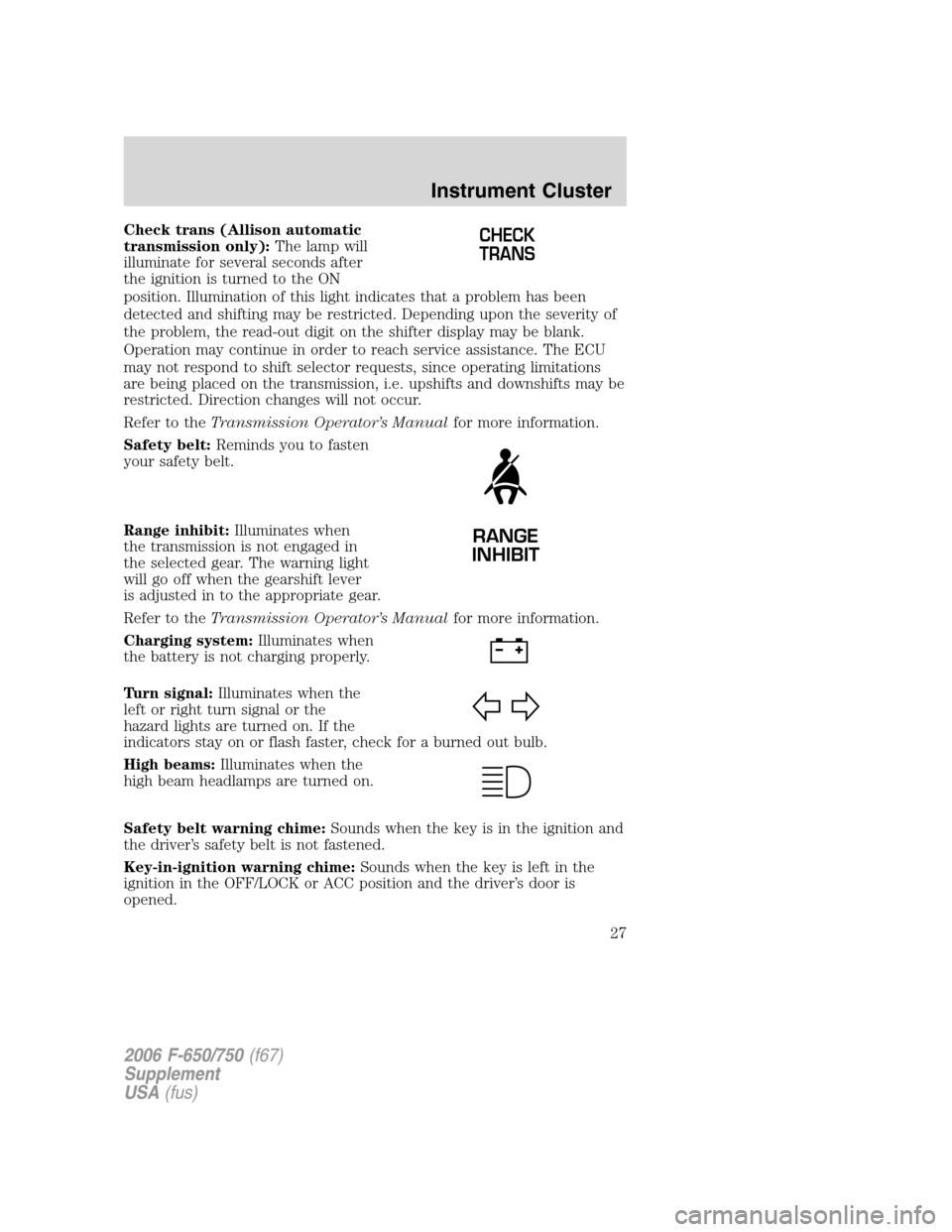
Check trans (Allison automatic
transmission only):The lamp will
illuminate for several seconds after
the ignition is turned to the ON
position. Illumination of this light indicates that a problem has been
detected and shifting may be restricted. Depending upon the severity of
the problem, the read-out digit on the shifter display may be blank.
Operation may continue in order to reach service assistance. The ECU
may not respond to shift selector requests, since operating limitations
are being placed on the transmission, i.e. upshifts and downshifts may be
restricted. Direction changes will not occur.
Refer to theTransmission Operator’s Manualfor more information.
Safety belt:Reminds you to fasten
your safety belt.
Range inhibit:Illuminates when
the transmission is not engaged in
the selected gear. The warning light
will go off when the gearshift lever
is adjusted in to the appropriate gear.
Refer to theTransmission Operator’s Manualfor more information.
Charging system:Illuminates when
the battery is not charging properly.
Turn signal:Illuminates when the
left or right turn signal or the
hazard lights are turned on. If the
indicators stay on or flash faster, check for a burned out bulb.
High beams:Illuminates when the
high beam headlamps are turned on.
Safety belt warning chime:Sounds when the key is in the ignition and
the driver’s safety belt is not fastened.
Key-in-ignition warning chime:Sounds when the key is left in the
ignition in the OFF/LOCK or ACC position and the driver’s door is
opened.CHECK
TRANS
RANGE
INHIBIT
2006 F-650/750(f67)
Supplement
USA(fus)
Instrument Cluster
27
Page 30 of 272
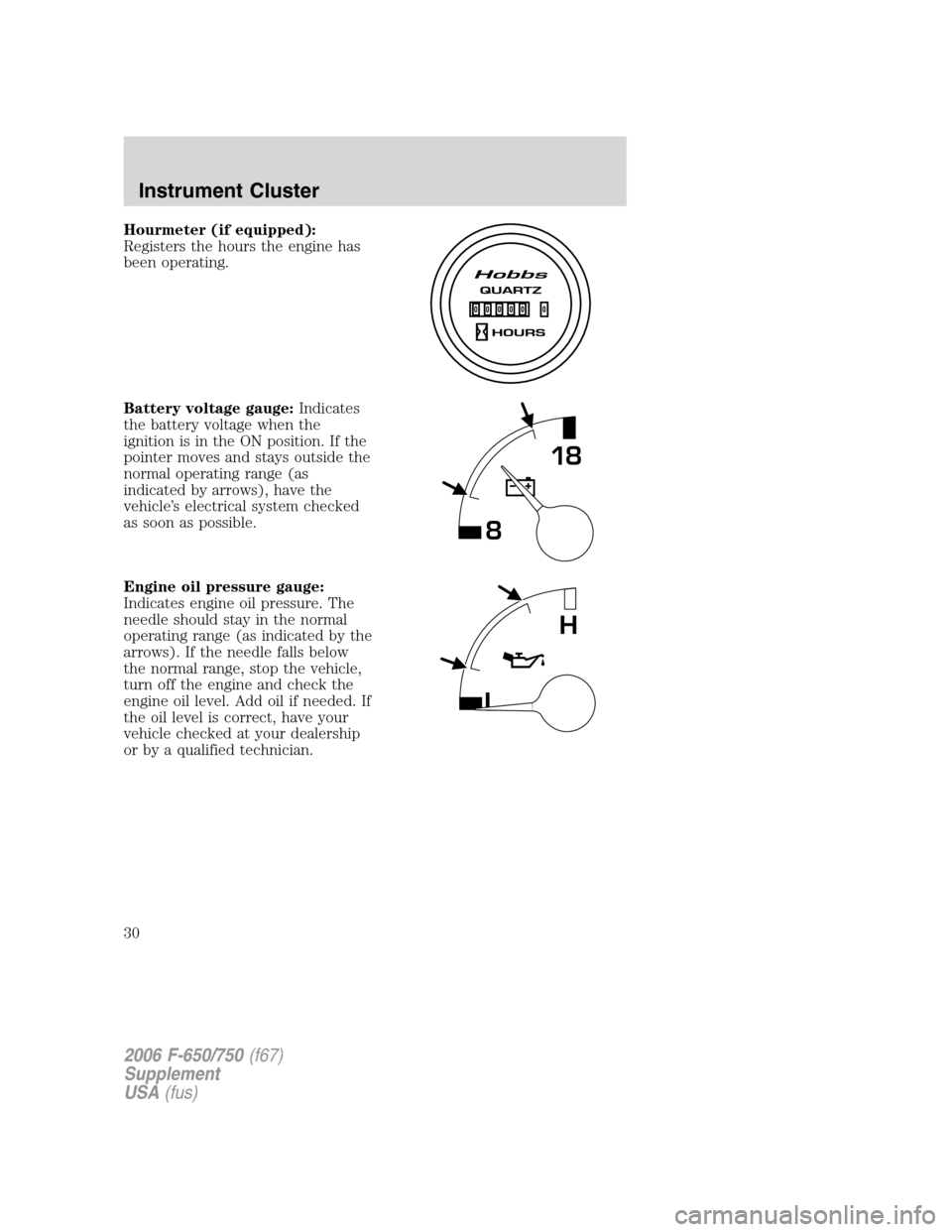
Hourmeter (if equipped):
Registers the hours the engine has
been operating.
Battery voltage gauge:Indicates
the battery voltage when the
ignition is in the ON position. If the
pointer moves and stays outside the
normal operating range (as
indicated by arrows), have the
vehicle’s electrical system checked
as soon as possible.
Engine oil pressure gauge:
Indicates engine oil pressure. The
needle should stay in the normal
operating range (as indicated by the
arrows). If the needle falls below
the normal range, stop the vehicle,
turn off the engine and check the
engine oil level. Add oil if needed. If
the oil level is correct, have your
vehicle checked at your dealership
or by a qualified technician.
818
L
H
2006 F-650/750(f67)
Supplement
USA(fus)
Instrument Cluster
30
Page 121 of 272
AUTOMATIC TRANSMISSION OPERATION (IF EQUIPPED)
Main transmission, auxiliary transmission, transfer case and power
take-off (PTO) control shift patterns can be found on a placard or decal
on the driver’s sun visor, on the instrument panel or on the shift control
itself.
The main transmission control is used to select the various gear ratios or
speeds of the transmission. Selecting D (Direct Drive), does not change
the transmission gear ratio, but is used where the gear ratios in the main
transmission are adequate to handle the vehicle operation.
If the transmission fails to shift properly, check the inline 10A fuse
located in the battery cables above the battery.
Hold the brake pedal down while you move the gearshift lever
between positions. If you don’t hold the brake pedal down, your
vehicle may move unexpectedly and cause property damage, personal
injury or death.
Allison 2500 automatic transmission
This transmission is available with a column-mounted gearshift lever. The
gear positions are displayed on the RNDL in the instrument cluster.
To avoid sudden, unexpected vehicle movement and
possible personal injury or death:
1. Bring the vehicle to a complete stop.
2. Shift the transmission into N (Neutral).
3. Apply the parking brake and make sure it is holding properly.
4. Turn the engine off when you leave the vehicle.Never leave the
vehicle unattended when the engine is running.
Allison 2200 automatic transmission with park pawl feature
Note:For Allison automatic transmission-equipped vehicles, also refer to
the separate Allison Transmission Operator’s Manual.
A parking pawl effectively grounds the transmission’s output shaft
preventing rotation of the driveline. If the vehicle is stationary, selecting
the P (Park) position places the transmission in neutral and engages the
parking pawl (always use the parking brake, also).
Note:If the P (Park) position is selected when the vehicle is in motion,
the parking pawl mechanism will ratchet andNOThold the truck.
2006 F-650/750(f67)
Supplement
USA(fus)
Driving
121
Page 143 of 272
GETTING ROADSIDE ASSISTANCE
To fully assist you should you have a vehicle concern, Ford offers a
complimentary roadside assistance program. This program is separate
from the New Vehicle Limited Warranty and is not applicable to vehicles
sold in Canada. The service is available:
•24–hours, seven days a week
•for the New Vehicle Limited Warranty period (U.S.) of two years
(unlimited miles)
Roadside assistance will cover:
•battery jump start.
•lock out assistance (key replacement is customer responsibility).
•towing – Ford/Mercury/Lincoln eligible vehicle towed to a
Ford/Mercury/Lincoln dealer within 35 miles (56.3 km) of the
disablement location or to the Nearest Qualified Ford/Mercury/Lincoln
dealer. If a member requests to be towed to a Ford/Mercury/Lincoln
dealer more than 35 miles (56.3 km) from the disablement location,
the member shall be responsible for any mileage costs in excess of 35
miles (56.3 km).
Trailers shall be covered up to $100 if the disabled Eligible Vehicles
requires service at the Nearest Qualified Dealer. If the trailer is disabled,
but the towing vehicle is operational, the trailer does not qualify for any
Roadside services.
Using roadside assistance
Complete the roadside assistance identification card and place it in your
wallet for quick reference. This card is found in the Owner Guide
portfolio in the glove compartment.
To receive roadside assistance in the United States, call 1-800-241-3673.
If you need to arrange roadside assistance for yourself, Ford will
reimburse a reasonable amount. To obtain information about
reimbursement, call 1-800-241-3673.
2006 F-650/750(f67)
Supplement
USA(fus)
Roadside Emergencies
143
Page 144 of 272
HAZARD FLASHER
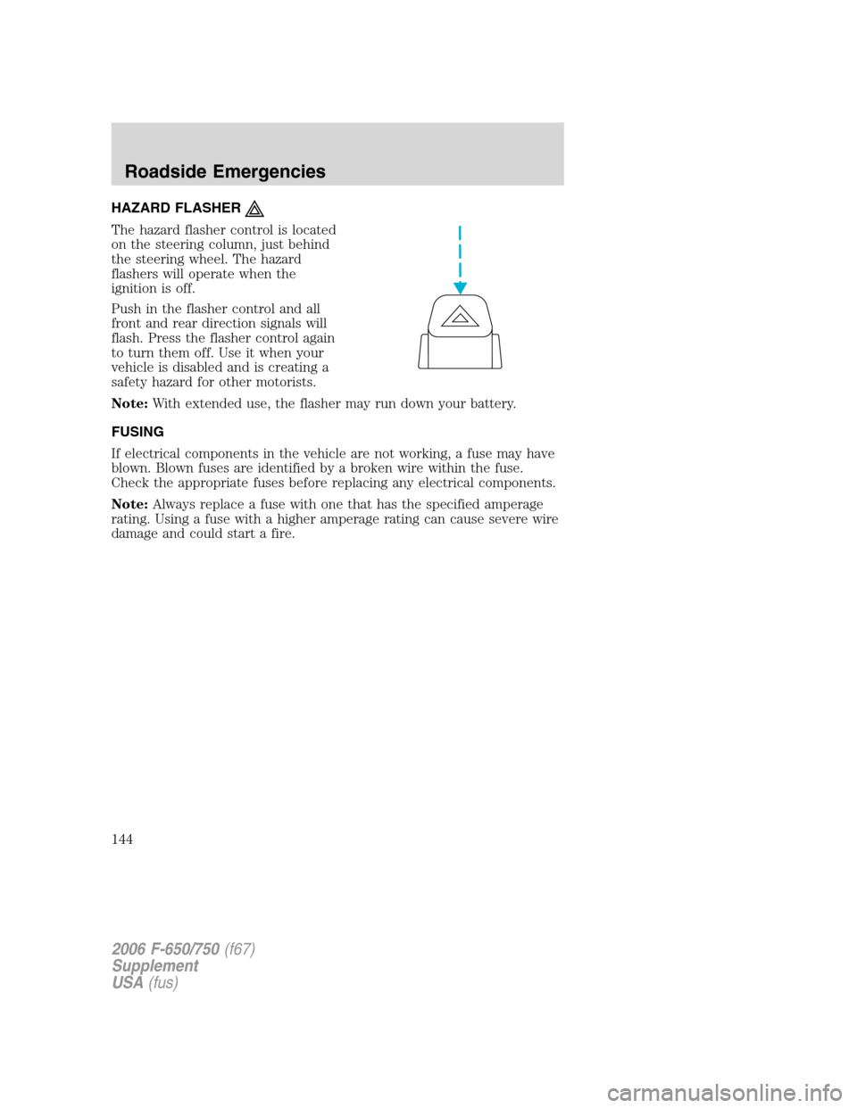
The hazard flasher control is located
on the steering column, just behind
the steering wheel. The hazard
flashers will operate when the
ignition is off.
Push in the flasher control and all
front and rear direction signals will
flash. Press the flasher control again
to turn them off. Use it when your
vehicle is disabled and is creating a
safety hazard for other motorists.
Note:With extended use, the flasher may run down your battery.
FUSING
If electrical components in the vehicle are not working, a fuse may have
blown. Blown fuses are identified by a broken wire within the fuse.
Check the appropriate fuses before replacing any electrical components.
Note:Always replace a fuse with one that has the specified amperage
rating. Using a fuse with a higher amperage rating can cause severe wire
damage and could start a fire.
2006 F-650/750(f67)
Supplement
USA(fus)
Roadside Emergencies
144
Page 147 of 272
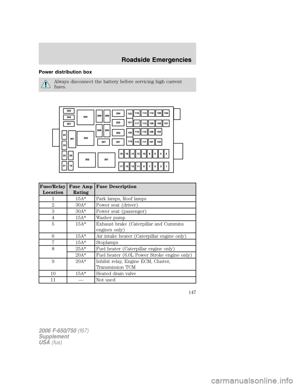
Power distribution box
Always disconnect the battery before servicing high current
fuses.
Fuse/Relay
LocationFuse Amp
RatingFuse Description
1 15A* Park lamps, Roof lamps
2 30A* Power seat (driver)
3 30A* Power seat (passenger)
4 15A* Washer pump
5 15A* Exhaust brake (Caterpillar and Cummins
engines only)
6 15A* Air intake heater (Caterpillar engine only)
7 15A* Stoplamps
8 25A* Fuel heater (Caterpillar engine only)
20A* Fuel heater (6.0L Power Stroke engine only)
9 20A* Inhibit relay, Engine ECM, Cluster,
Transmission TCM
10 15A* Heated drain valve
11 — Not used
2006 F-650/750(f67)
Supplement
USA(fus)
Roadside Emergencies
147
Page 148 of 272
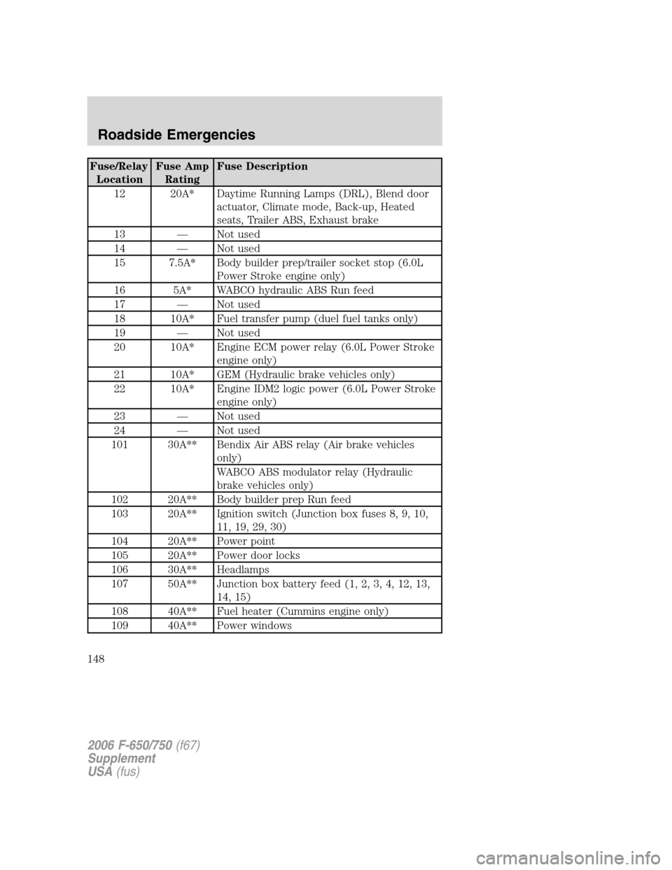
Fuse/Relay
LocationFuse Amp
RatingFuse Description
12 20A* Daytime Running Lamps (DRL), Blend door
actuator, Climate mode, Back-up, Heated
seats, Trailer ABS, Exhaust brake
13 — Not used
14 — Not used
15 7.5A* Body builder prep/trailer socket stop (6.0L
Power Stroke engine only)
16 5A* WABCO hydraulic ABS Run feed
17 — Not used
18 10A* Fuel transfer pump (duel fuel tanks only)
19 — Not used
20 10A* Engine ECM power relay (6.0L Power Stroke
engine only)
21 10A* GEM (Hydraulic brake vehicles only)
22 10A* Engine IDM2 logic power (6.0L Power Stroke
engine only)
23 — Not used
24 — Not used
101 30A** Bendix Air ABS relay (Air brake vehicles
only)
WABCO ABS modulator relay (Hydraulic
brake vehicles only)
102 20A** Body builder prep Run feed
103 20A** Ignition switch (Junction box fuses 8, 9, 10,
11, 19, 29, 30)
104 20A** Power point
105 20A** Power door locks
106 30A** Headlamps
107 50A** Junction box battery feed (1, 2, 3, 4, 12, 13,
14, 15)
108 40A** Fuel heater (Cummins engine only)
109 40A** Power windows
2006 F-650/750(f67)
Supplement
USA(fus)
Roadside Emergencies
148
Page 149 of 272
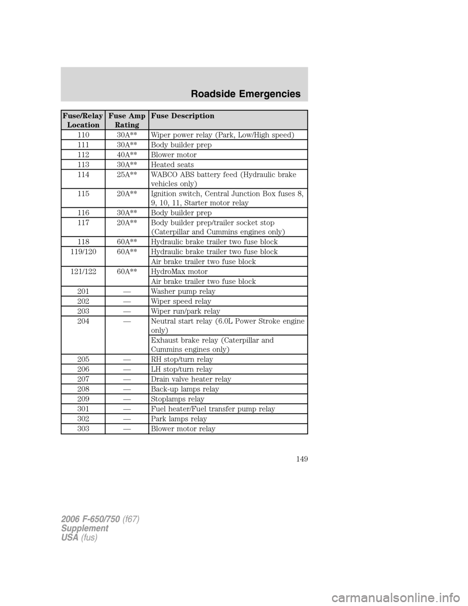
Fuse/Relay
LocationFuse Amp
RatingFuse Description
110 30A** Wiper power relay (Park, Low/High speed)
111 30A** Body builder prep
112 40A** Blower motor
113 30A** Heated seats
114 25A** WABCO ABS battery feed (Hydraulic brake
vehicles only)
115 20A** Ignition switch, Central Junction Box fuses 8,
9, 10, 11, Starter motor relay
116 30A** Body builder prep
117 20A** Body builder prep/trailer socket stop
(Caterpillar and Cummins engines only)
118 60A** Hydraulic brake trailer two fuse block
119/120 60A** Hydraulic brake trailer two fuse block
Air brake trailer two fuse block
121/122 60A** HydroMax motor
Air brake trailer two fuse block
201 — Washer pump relay
202 — Wiper speed relay
203 — Wiper run/park relay
204 — Neutral start relay (6.0L Power Stroke engine
only)
Exhaust brake relay (Caterpillar and
Cummins engines only)
205 — RH stop/turn relay
206 — LH stop/turn relay
207 — Drain valve heater relay
208 — Back-up lamps relay
209 — Stoplamps relay
301 — Fuel heater/Fuel transfer pump relay
302 — Park lamps relay
303 — Blower motor relay
2006 F-650/750(f67)
Supplement
USA(fus)
Roadside Emergencies
149