FORD F650 2007 11.G Owners Manual
Manufacturer: FORD, Model Year: 2007, Model line: F650, Model: FORD F650 2007 11.GPages: 280, PDF Size: 1.93 MB
Page 141 of 280
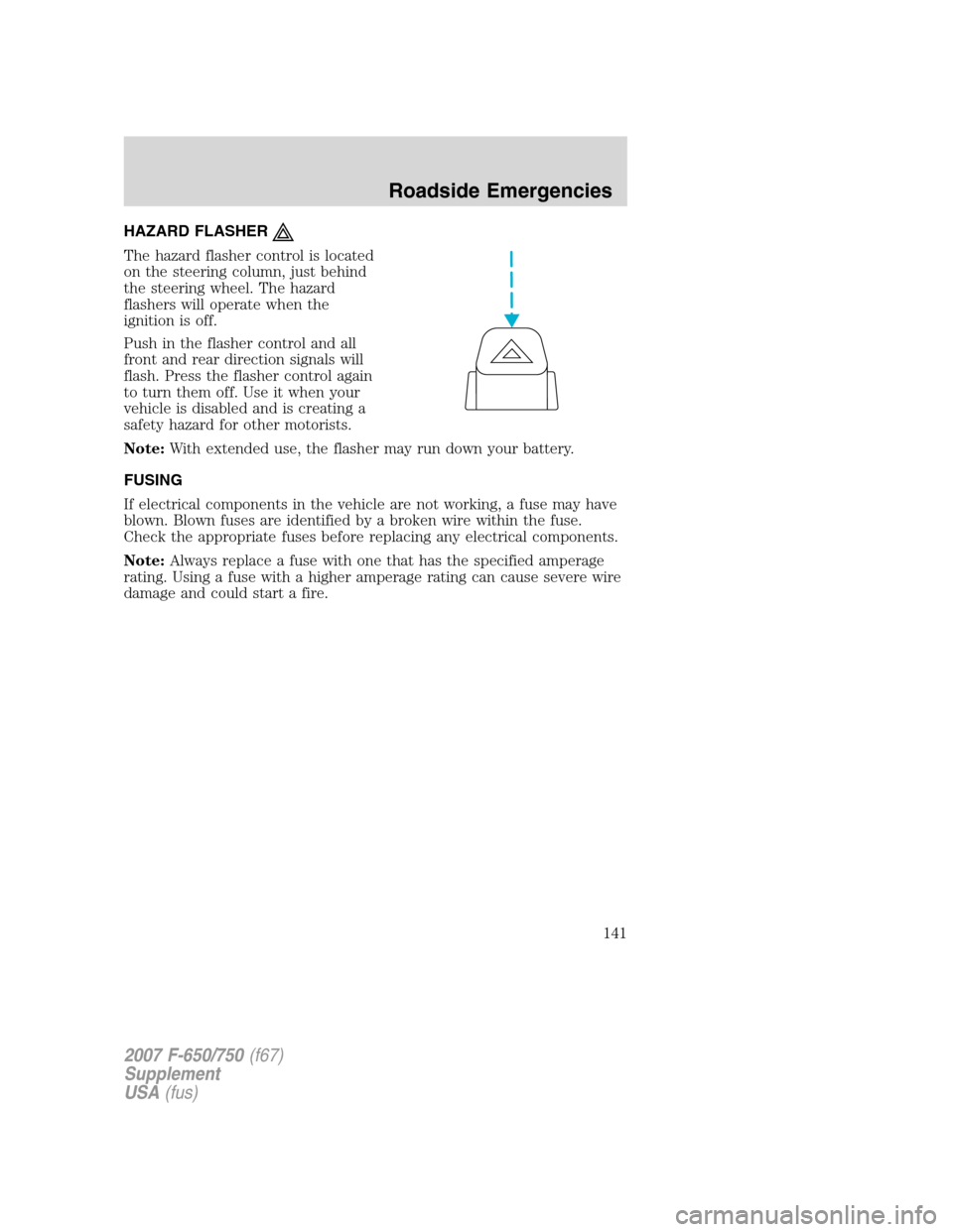
HAZARD FLASHER
The hazard flasher control is located
on the steering column, just behind
the steering wheel. The hazard
flashers will operate when the
ignition is off.
Push in the flasher control and all
front and rear direction signals will
flash. Press the flasher control again
to turn them off. Use it when your
vehicle is disabled and is creating a
safety hazard for other motorists.
Note:With extended use, the flasher may run down your battery.
FUSING
If electrical components in the vehicle are not working, a fuse may have
blown. Blown fuses are identified by a broken wire within the fuse.
Check the appropriate fuses before replacing any electrical components.
Note:Always replace a fuse with one that has the specified amperage
rating. Using a fuse with a higher amperage rating can cause severe wire
damage and could start a fire.
2007 F-650/750(f67)
Supplement
USA(fus)
Roadside Emergencies
141
Page 142 of 280
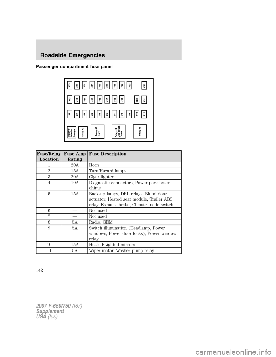
Passenger compartment fuse panel
Fuse/Relay
LocationFuse Amp
RatingFuse Description
1 20A Horn
2 15A Turn/Hazard lamps
3 20A Cigar lighter
4 10A Diagnostic connectors, Power park brake
chime
5 15A Back-up lamps, DRL relays, Blend door
actuator, Heated seat module, Trailer ABS
relay, Exhaust brake, Climate mode switch
6 — Not used
7 — Not used
8 5A Radio, GEM
9 5A Switch illumination (Headlamp, Power
windows, Power door locks), Power window
relay
10 15A Heated/Lighted mirrors
11 5A Wiper motor, Washer pump relay
2007 F-650/750(f67)
Supplement
USA(fus)
Roadside Emergencies
142
Page 143 of 280
Fuse/Relay
LocationFuse Amp
RatingFuse Description
12 10A Stoplamp switch (Hydraulic brake vehicles
only)
13 20A Radio, Cluster
14 10A Interior lamps
15 10A GEM, Interior lamp relay, Map lamps
16 15A High beams
17 — Not used
18 5A Headlamp switch
19 15A Engine ECM (Caterpillar and Cummins
engines)
Engine ECM, Accel, Crank (6.0L Power
Stroke engine only)
20 5A Starter relay
21 10A Daytime Running Lamps (DRL)
22 15A Air solenoid 4–pack (Air horn, Air suspension
dump, Differential lock axle and Two-speed
axle)
23 10A Electronic flasher
24 15A Vacuum pump, Air dryer, ABS, Fuel
heater/Fuel transfer pump relay, Heated
drain valve, 6.0L Power Stroke Water In Fuel
(WIF) module
25 10A Blower motor relay
26 10A RH low beam headlamp
27 — Not used
28 10A LH low beam headlamp
29 10A Cluster (Power, Warning lamps), Hydraulic
ABS relay, Air traction control, GEM,
Hourmeter, Transmission temp
30 15A Allison transmissions
31 15A Not used
Relay 1 — Interior lamps
2007 F-650/750(f67)
Supplement
USA(fus)
Roadside Emergencies
143
Page 144 of 280
Fuse/RelayLocation Fuse Amp
Rating Fuse Description
Relay 2 — Not used
Relay 3 — Horn
Relay 4 — One-touch down window
Relay 5 — Not used
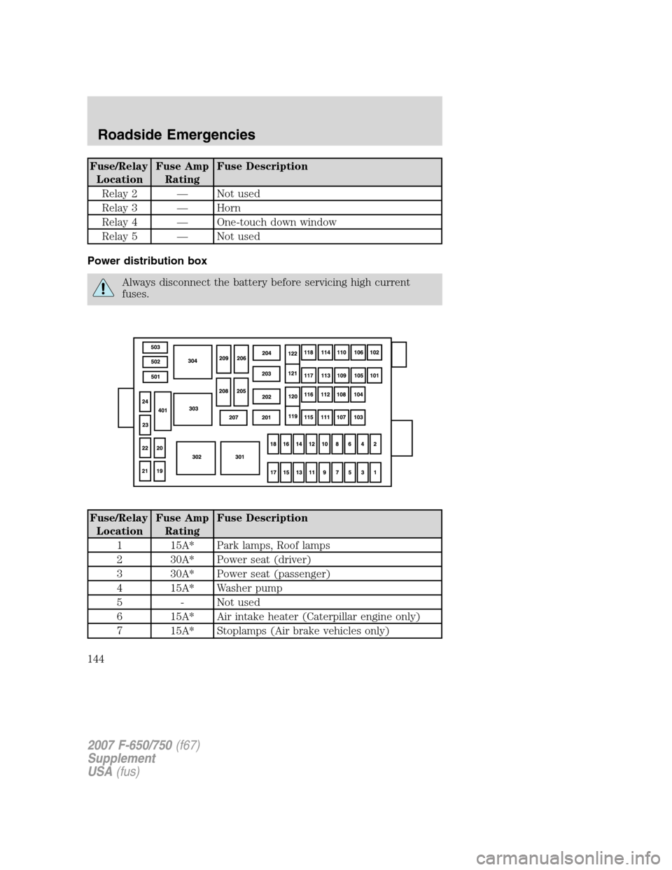
Power distribution box
Always disconnect the battery before servicing high current
fuses.
Fuse/Relay Location Fuse Amp
Rating Fuse Description
1 15A* Park lamps, Roof lamps
2 30A* Power seat (driver)
3 30A* Power seat (passenger)
4 15A* Washer pump
5 - Not used
6 15A* Air intake heater (Caterpillar engine only)
7 15A* Stoplamps (Air brake vehicles only)
2007 F-650/750 (f67)
Supplement
USA (fus)
Roadside Emergencies
144
Page 145 of 280
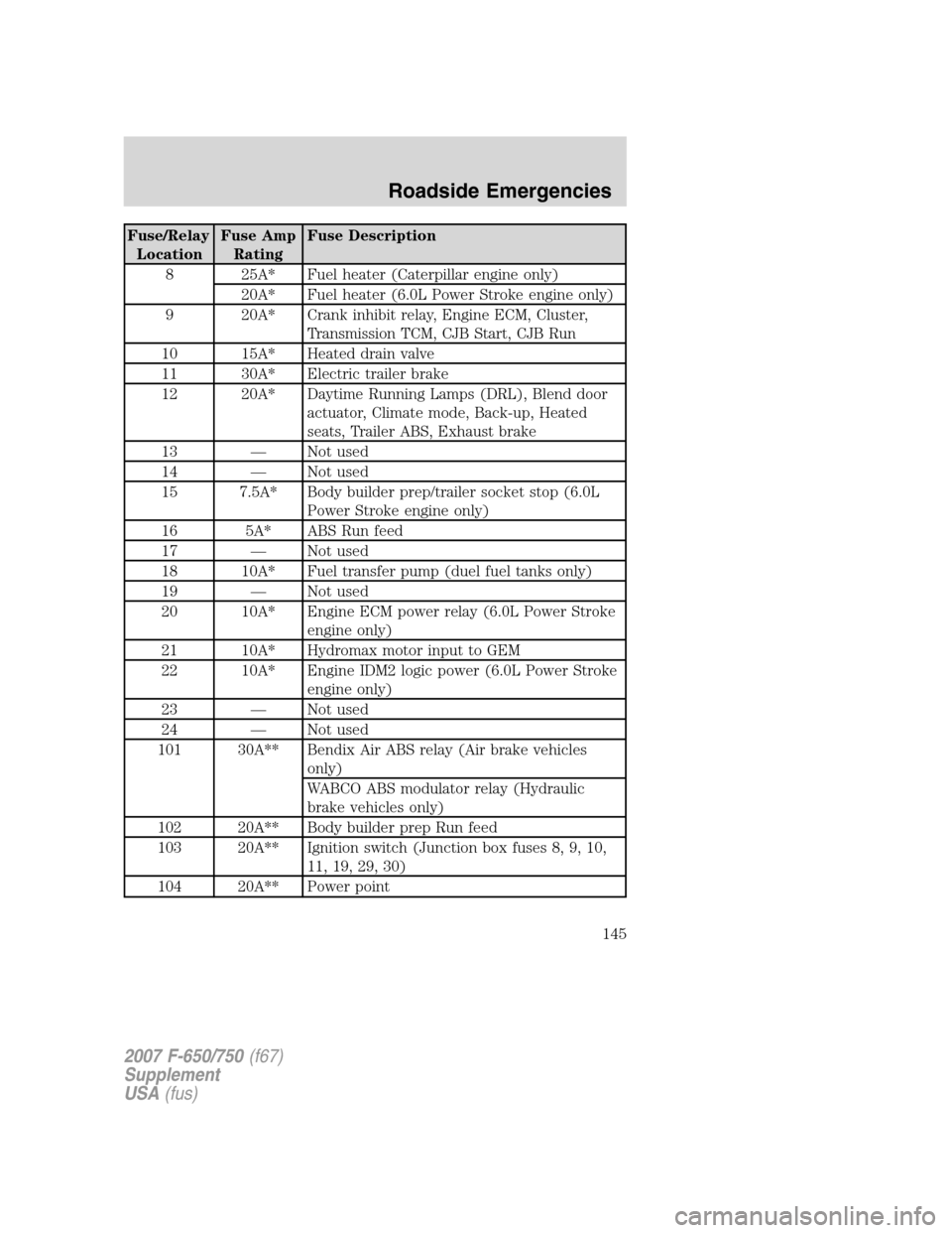
Fuse/Relay
LocationFuse Amp
RatingFuse Description
8 25A* Fuel heater (Caterpillar engine only)
20A* Fuel heater (6.0L Power Stroke engine only)
9 20A* Crank inhibit relay, Engine ECM, Cluster,
Transmission TCM, CJB Start, CJB Run
10 15A* Heated drain valve
11 30A* Electric trailer brake
12 20A* Daytime Running Lamps (DRL), Blend door
actuator, Climate mode, Back-up, Heated
seats, Trailer ABS, Exhaust brake
13 — Not used
14 — Not used
15 7.5A* Body builder prep/trailer socket stop (6.0L
Power Stroke engine only)
16 5A* ABS Run feed
17 — Not used
18 10A* Fuel transfer pump (duel fuel tanks only)
19 — Not used
20 10A* Engine ECM power relay (6.0L Power Stroke
engine only)
21 10A* Hydromax motor input to GEM
22 10A* Engine IDM2 logic power (6.0L Power Stroke
engine only)
23 — Not used
24 — Not used
101 30A** Bendix Air ABS relay (Air brake vehicles
only)
WABCO ABS modulator relay (Hydraulic
brake vehicles only)
102 20A** Body builder prep Run feed
103 20A** Ignition switch (Junction box fuses 8, 9, 10,
11, 19, 29, 30)
104 20A** Power point
2007 F-650/750(f67)
Supplement
USA(fus)
Roadside Emergencies
145
Page 146 of 280
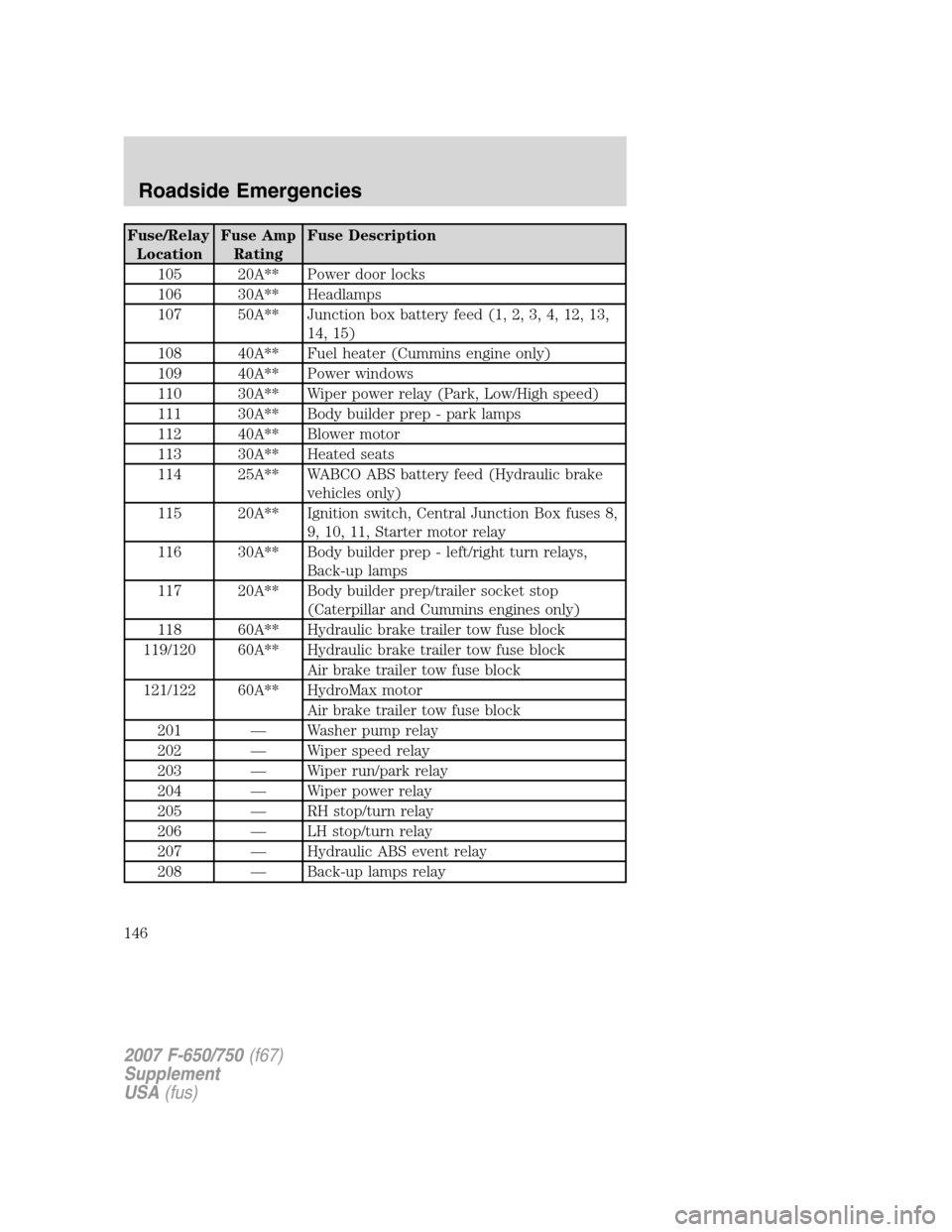
Fuse/Relay
LocationFuse Amp
RatingFuse Description
105 20A** Power door locks
106 30A** Headlamps
107 50A** Junction box battery feed (1, 2, 3, 4, 12, 13,
14, 15)
108 40A** Fuel heater (Cummins engine only)
109 40A** Power windows
110 30A** Wiper power relay (Park, Low/High speed)
111 30A** Body builder prep - park lamps
112 40A** Blower motor
113 30A** Heated seats
114 25A** WABCO ABS battery feed (Hydraulic brake
vehicles only)
115 20A** Ignition switch, Central Junction Box fuses 8,
9, 10, 11, Starter motor relay
116 30A** Body builder prep - left/right turn relays,
Back-up lamps
117 20A** Body builder prep/trailer socket stop
(Caterpillar and Cummins engines only)
118 60A** Hydraulic brake trailer tow fuse block
119/120 60A** Hydraulic brake trailer tow fuse block
Air brake trailer tow fuse block
121/122 60A** HydroMax motor
Air brake trailer tow fuse block
201 — Washer pump relay
202 — Wiper speed relay
203 — Wiper run/park relay
204 — Wiper power relay
205 — RH stop/turn relay
206 — LH stop/turn relay
207 — Hydraulic ABS event relay
208 — Back-up lamps relay
2007 F-650/750(f67)
Supplement
USA(fus)
Roadside Emergencies
146
Page 147 of 280
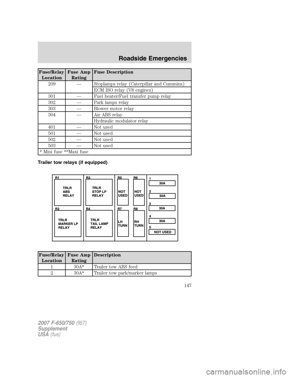
Fuse/Relay
LocationFuse Amp
RatingFuse Description
209 — Stoplamps relay (Caterpillar and Cummins)
ECM ISO relay (V8 engines)
301 — Fuel heater/Fuel transfer pump relay
302 — Park lamps relay
303 — Blower motor relay
304 — Air ABS relay
Hydraulic modulator relay
401 — Not used
501 — Not used
502 — Not used
503 — Not used
* Mini fuse **Maxi fuse
Trailer tow relays (if equipped)
Fuse/Relay
LocationFuse Amp
RatingDescription
1 30A* Trailer tow ABS feed
2 30A* Trailer tow park/marker lamps
2007 F-650/750(f67)
Supplement
USA(fus)
Roadside Emergencies
147
Page 148 of 280
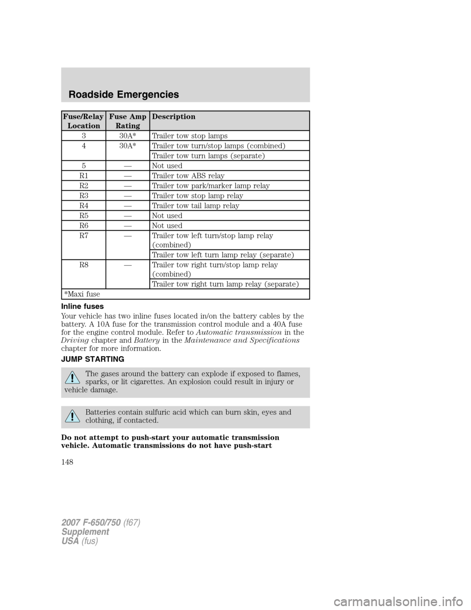
Fuse/Relay
LocationFuse Amp
RatingDescription
3 30A* Trailer tow stop lamps
4 30A* Trailer tow turn/stop lamps (combined)
Trailer tow turn lamps (separate)
5 — Not used
R1 — Trailer tow ABS relay
R2 — Trailer tow park/marker lamp relay
R3 — Trailer tow stop lamp relay
R4 — Trailer tow tail lamp relay
R5 — Not used
R6 — Not used
R7 — Trailer tow left turn/stop lamp relay
(combined)
Trailer tow left turn lamp relay (separate)
R8 — Trailer tow right turn/stop lamp relay
(combined)
Trailer tow right turn lamp relay (separate)
*Maxi fuse
Inline fuses
Your vehicle has two inline fuses located in/on the battery cables by the
battery. A 10A fuse for the transmission control module and a 40A fuse
for the engine control module. Refer toAutomatic transmissionin the
Drivingchapter andBatteryin theMaintenance and Specifications
chapter for more information.
JUMP STARTING
The gases around the battery can explode if exposed to flames,
sparks, or lit cigarettes. An explosion could result in injury or
vehicle damage.
Batteries contain sulfuric acid which can burn skin, eyes and
clothing, if contacted.
Do not attempt to push-start your automatic transmission
vehicle. Automatic transmissions do not have push-start
2007 F-650/750(f67)
Supplement
USA(fus)
Roadside Emergencies
148
Page 149 of 280
capability. Attempting to push-start a vehicle with an automatic
transmission may cause transmission damage.
Before connecting a fast-charger, booster battery or installing a new
battery, make sure the ground polarities of the fast-charger, booster
battery or alternator (when installing a battery) are matched to the
ground polarity of the vehicle battery. Improper usage of the
fast-charger, hook-up of booster battery or installation of a new battery
can cause damage to the electrical system or to the alternator. Do not
attempt to polarize the alternator.
Preparing your vehicle
1.Use only a 12–volt supply to start your vehicle.Do not attach the
jumper cables to the glow plug relay as this could severely damage the
glow plugs, injector driver module and PCM.
2. Do not disconnect the battery of the disabled vehicle as this could
damage the vehicle’s electrical system.
3. Park the booster vehicle close to the hood of the disabled vehicle
making sure the two vehiclesdo nottouch. Set the parking brake on
both vehicles and stay clear of the engine cooling fan and other moving
parts.
4. Check all battery terminals and remove any excessive corrosion before
you attach the battery cables. Ensure that vent caps are tight and level.
5. Turn the heater fan on in both vehicles to protect any electrical
surges. Turn all other accessories off.
Connecting the jumper cables
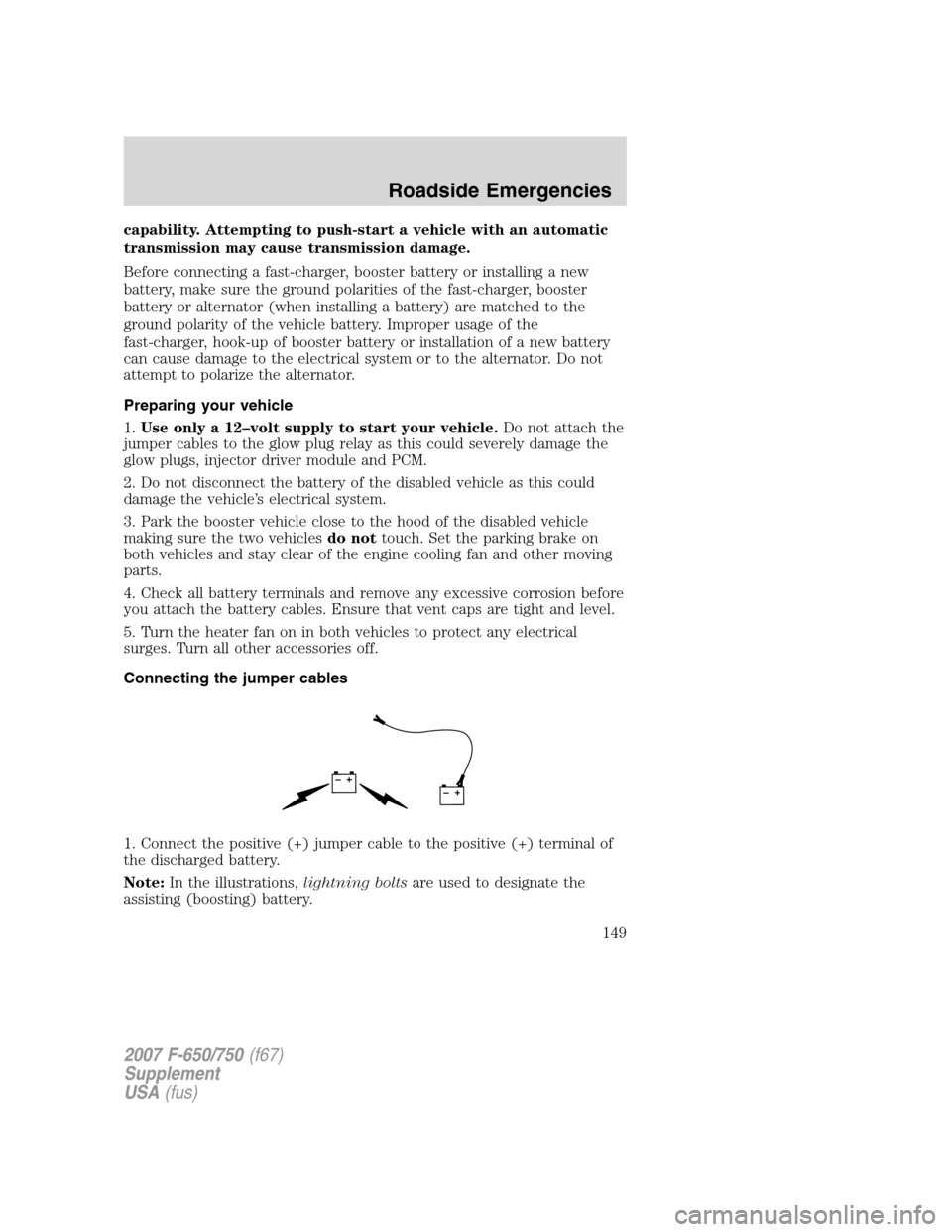
1. Connect the positive (+) jumper cable to the positive (+) terminal of
the discharged battery.
Note:In the illustrations,lightning boltsare used to designate the
assisting (boosting) battery.
+–+–
2007 F-650/750(f67)
Supplement
USA(fus)
Roadside Emergencies
149
Page 150 of 280
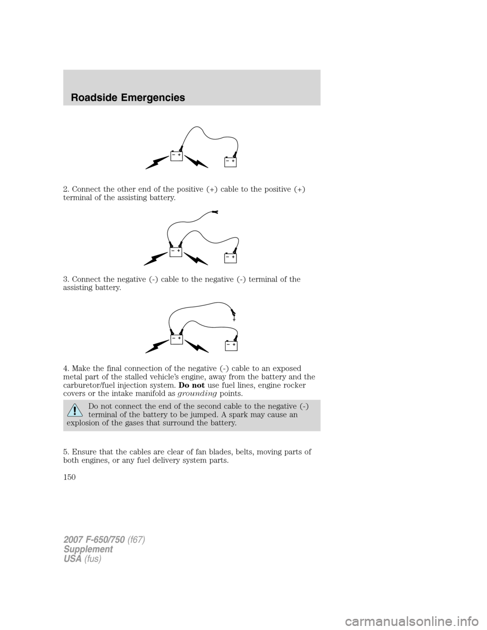
2. Connect the other end of the positive (+) cable to the positive (+)
terminal of the assisting battery.
3. Connect the negative (-) cable to the negative (-) terminal of the
assisting battery.
4. Make the final connection of the negative (-) cable to an exposed
metal part of the stalled vehicle’s engine, away from the battery and the
carburetor/fuel injection system.Do notuse fuel lines, engine rocker
covers or the intake manifold asgroundingpoints.
Do not connect the end of the second cable to the negative (-)
terminal of the battery to be jumped. A spark may cause an
explosion of the gases that surround the battery.
5. Ensure that the cables are clear of fan blades, belts, moving parts of
both engines, or any fuel delivery system parts.
+–+–
+–+–
+–+–
2007 F-650/750(f67)
Supplement
USA(fus)
Roadside Emergencies
150